

Page 1
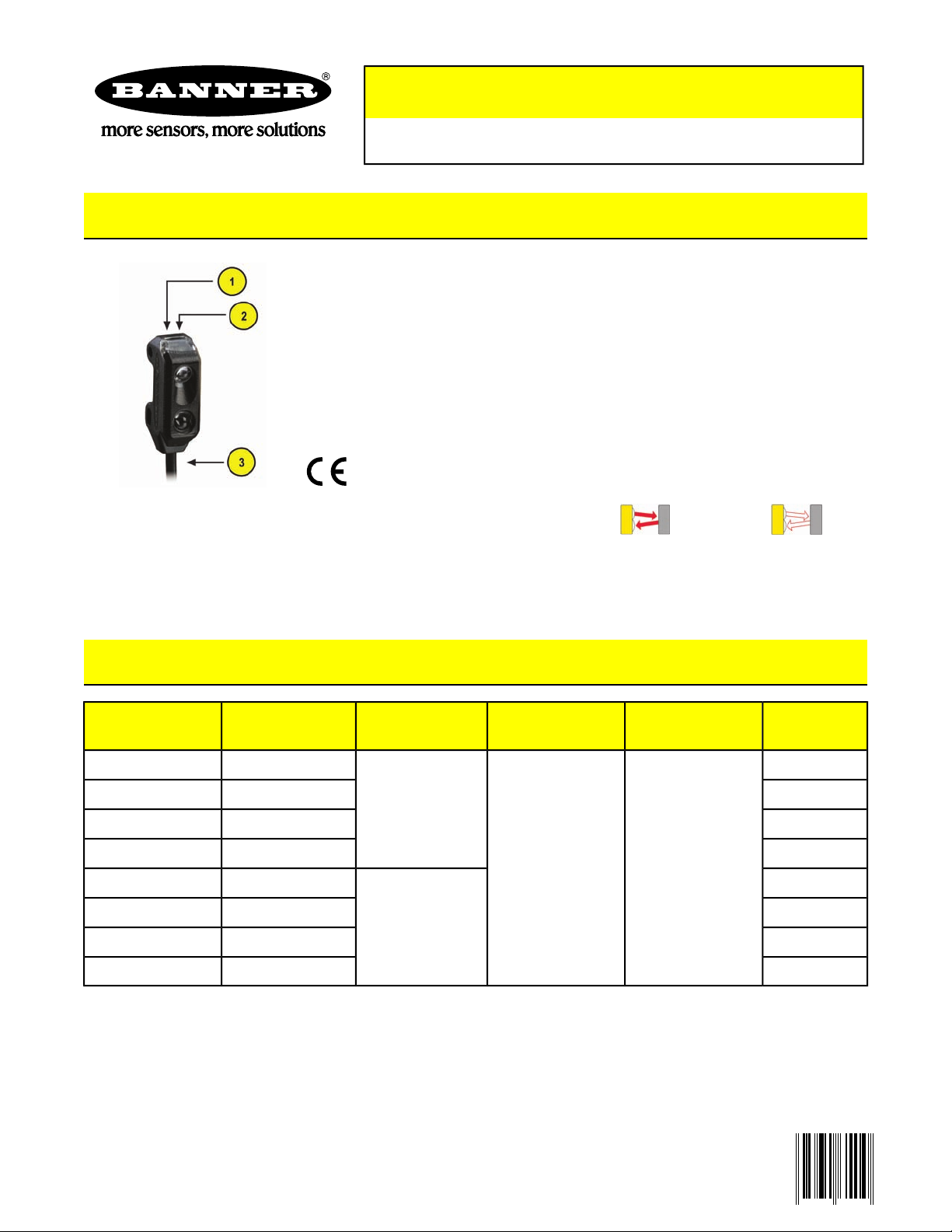
1. Power ON Indicator
_564 65_N
2. Received Signal Indicator
3. 2 m Cable or Pigtail Quick-Disconnect
VS1 Series
Miniature, Self-Contained Convergent-Mode Sensors
Features
• Totally self-contained miniature sensors
• 10 to 30V dc operation
• Visible red or infrared sensing beam, depending on model
• 10 mm (0.4") or 15 mm (0.6") convergent point, depending on model
• NPN (sinking) or PNP (sourcing) output, and dark or light operate,
depending on model
• 3-wire hookup; output load capacity to 50 mA
• Choice of integral cable or pigtail quick-disconnect connector
ConvergentConvergent
Infrared, 865 nmVisible Red, 630 nm
Models
Visible Red Beam
Models
* Only standard 2 m (6.5') cable models are listed above. For other cable/connector options:
• 9 m cables: add suffix “W/30” to the model number (e.g., VS1AN5CV10 W/30).
• 150 mm (6") pigtail with threaded 3-pin Pico-style QD: add suffix “Q” to the model number (e.g., VS1AN5CV10Q).
A model with a QD connector requires a mating cable; see Quick-Disconnect (QD) Cordsets on page 5.
Infrared Beam
Models
VS1AN5C10VS1AN5CV10
VS1AN5C20VS1AN5CV20
10 mm (0.4")
15 mm (0.6")
2 m (6.5') 3-wire
integral cable
Output TypeSupply VoltageCable*Focus
NPN/LO
NPN/DOVS1RN5C10VS1RN5CV10
PNP/LOVS1AP5C10VS1AP5CV10
PNP/DOVS1RP5C10VS1RP5CV10
10 to 30V dc
NPN/LO
NPN/DOVS1RN5C20VS1RN5CV20
PNP/LOVS1AP5C20VS1AP5CV20
PNP/DOVS1RP5C20VS1RP5CV20
11/2009P/N _56465_ rev. D
Page 2
VS1 Series
Overview
VS1 Series miniature self-contained sensors are designed for precision sensing in small areas previously accessible
only to remote or fiber optic models.Typical applications include mounting inside vibrating feeders and electronic
component handling equipment, where larger sensors will not fit.
The sensing energy of a convergent-mode sensor is concentrated at the specified f ocus point (see Models on page
1). Convergent-mode sensors are less sensitive to background reflections, compared with diffuse-mode sensors.
Contact the factory if background reflections are a problem.
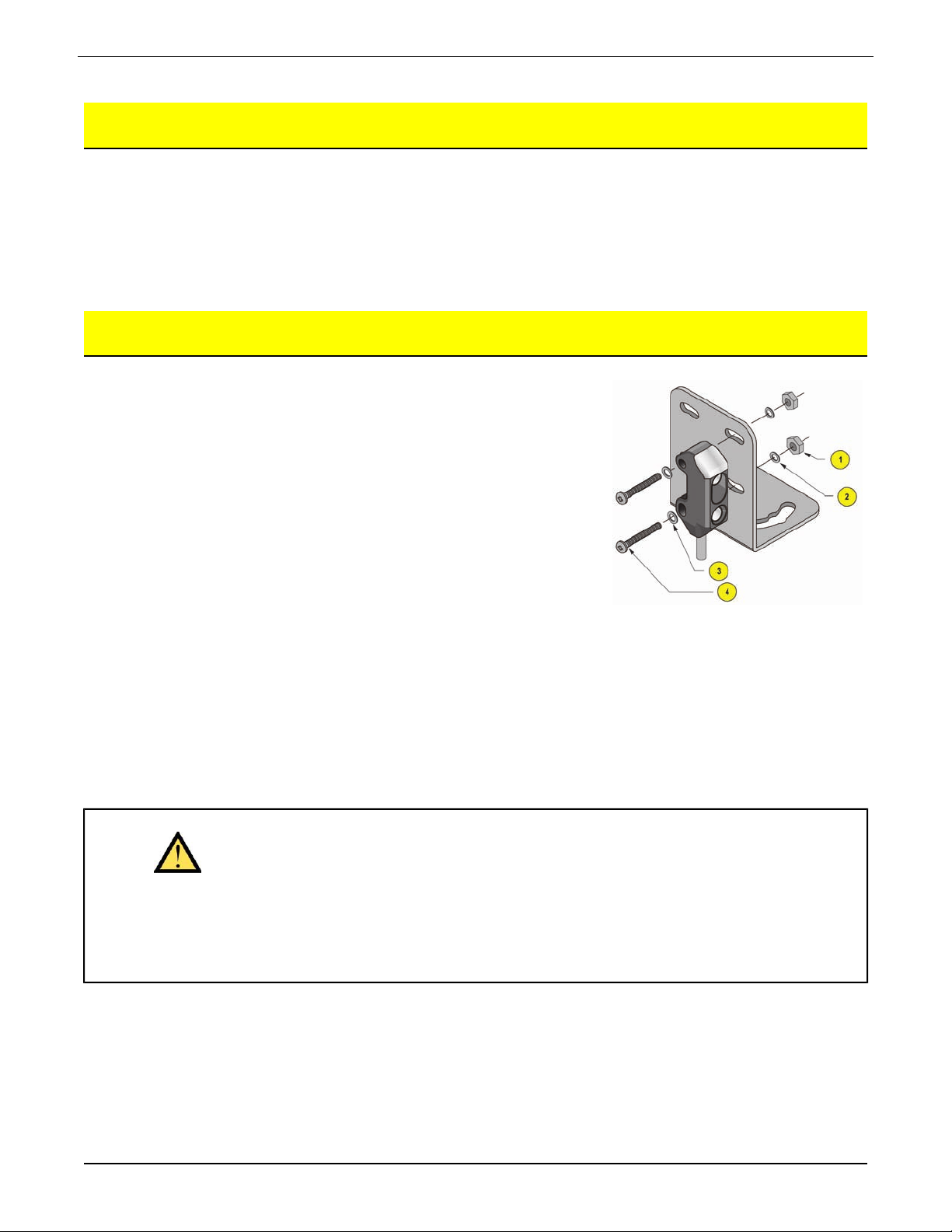
Installation Notes
Included with each sensor is a hardware packet containing two stainless
steel M2 x 0.4 x 16 mm Phillips pan-head machine screws, flat washers, loc k
washers, and hex nuts.To mount the sensor, use the supplied flat washer
against the front surface of the sensor housing, between it and the screw
head. If mounting to one of the optional brackets, place the lock washer
against the back of the bracket, followed by the nut. If mounting directly to
a threaded hole, place the lock washer between the scre w head and the flat
washer (see Figure 1).
For best results, mount the VS1 where it is protected from moisture, high
humidity and dirt.
Figure 1. Sensor Mounting
1. Hex Nut (2)
2. Lock Washer (2)
3. Washer (2)
4. M2 x 0.4 x 16 mm Phillips
Pan-head Machine Screw (2)
WARNING . . . Not To Be Used for Personnel Protection
Never use this product as a sensing device for personnel protection. Doing so
could lead to serious injury or death
This product does NOT include the self-checking redundant circuitry necessary to allow its use in personnel safety
applications. A sensor f ailure or malfunction can cause either an energiz ed or denergized sensor output condition.
Consult your Banner Safety Products catalog for safety products that meet OSHA, ANSI and IEC standards for
personnel protection.
2
Tel: 763.544.3164
P/N _56465_ rev. DBanner Engineering Corp. - Minneapolis, MN USA - www.bannerengineering.com
Page 3

VS1 Series
Current
Circuitry
Specifications
DescriptionFeature
10 to 30V dc (10% maximum ripple) at less than 25 mA (exclusive of load)Supply Voltage and
Protected against reverse polarity and transient voltagesSupply Protection
Output Configuration
Output Rating
Output Protection
Circuitry
Indicators
SPST solid-state switch
NPN (current sinking) or PNP (current sourcing), depending on model
Light operate (N.O.) or dark operate (N.C.), depending on model
50 mA maximum
OFF-state leakage current: < 1 microamp at 24V dc
ON-state saturation voltage: < 0.25V at 10 mA dc; < 0.5V at 50 mA dc
Protected against false pulse on power-up and continuous overload or short circuit of
outputs. Overload trip point 100 mA.
1 millisecond ON and OFFOutput Response Time
250 microsecondsRepeatability
Two LEDs: Green and Yellow
Green ON steady: sensor power ON
Green flashing: output overload
Yellow ON steady: light is sensed
Yellow flashing: marginal excess gain (1-1.5x) in light condition
Black ABS/polycarbonate housing with clear acrylic lensConstruction
Connections
Operating Conditions
Application Notes
Certifications
P/N _56465_ rev. D
IP54; NEMA 3Environmental Rating
2 m (6.5') attached cable: three #28 ga stranded conductors with PE insulation; PVC
outer cable jacket; or pigtail with 3-pin Pico-style quick-disconnect fitting. QD cab les are
ordered separately.
Temperature: –20° to +55° C (–4° to +131° F)
Maximum Relative Humidity: 80% at 50° C (non-condensing)
M2 stainless steel mounting hardware included (see “Installation Notes”). Optional
mounting brackets are available (see Accessory Mounting Brackets on page 6).
3Banner Engineering Corp. - Minneapolis, MN USA - www.bannerengineering.com
Tel: 763.544.3164
Page 4

VS1...CV10
VS1...CV20
VS1 Series
Performance Curves
Visible Red Beam Models
Beam PatternExcess Gain
Performance based on 90% reflectance white card test
VS1...C10
VS1...C20
Y: Excess GainX: Distance
Infrared Beam Models
Beam PatternExcess Gain
Performance based on 90% reflectance white card test
Y: Beam PatternX: Distance
Y: Excess GainX: Distance
4
Tel: 763.544.3164
Y: Beam PatternX: Distance
P/N _56465_ rev. DBanner Engineering Corp. - Minneapolis, MN USA - www.bannerengineering.com
Page 5

34.7 mm
(1.37")
9.6 mm
(0.38")
M8 x 1
4
3
1
VS1 Series
Dimensions
1. 150 mm (6") Pigtail
3-pin Pico-style
straight with M8
threads
Hookups
QD hookups are shown. Cabled hookups are functionally identical.
Quick-Disconnect (QD) Cordsets
PKG3M-2
PKG3M-9
2 m (6.5')
9 m (30')
Key:PNP OutputsNPN Outputs
1 = Brown
3 = Blue
4 = Black
X = Load
PinoutDimensionsLengthModelStyle
Female
Wiring Key:
1 = Brown
3 = Blue
4 = Black
P/N _56465_ rev. D
Tel: 763.544.3164
5Banner Engineering Corp. - Minneapolis, MN USA - www.bannerengineering.com
Page 6

Accessory Mounting Brackets
SMBVS1TCSMBVS1T
•• Tall compact bracketTall bracket
• •300 series stainless steel 300 series stainless steel
VS1 Series
SMBVS1SCSMBVS1S
•• Tall compact bracketTall compact bracket
• •300 series stainless steel 300 series stainless steel
Warranty: Banner Engineering Corp. will repair or replace, free of charge, any product
of its manufacture found to be def ective at the time it is returned to the f actory during
the warranty period.This warranty does not cover damage or liability f or the improper
application of Banner products.This warranty is in lieu of any other warranty either
expressed or implied.
 Loading...