

Page 1
Product
Line
Specifications
VALU-BEAM® Sensors
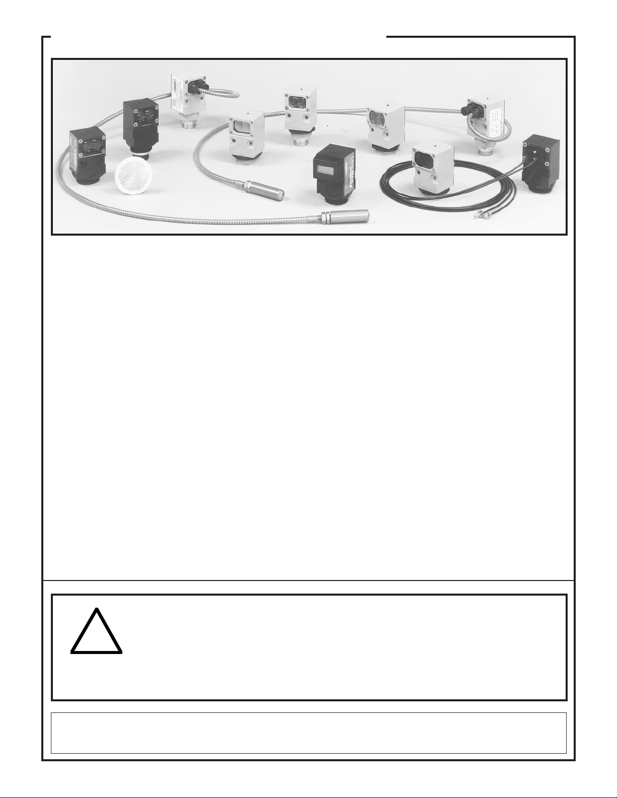
Rugged, self-contained photoelectric sensors for industrial applications
Economy, performance, and durability in a family of rugged,
•
self-contained sensors for demanding industrial applications
912 Series sensors have solid-state outputs; models for either
•
10-30V dc or 24-250V ac operation (pages 4 to 9)
915 Series sensors have electromechanical relay output; models
•
for 12-28V ac/dc, 90-130V ac, or 210-250V ac (pages 10 to 13)
990 Series sensors output to a built-in 6-digit totalizing counter;
•
operate from both 12-115V dc and 10-250V ac (pages 14 to 17)
Many models available in opposed, retroreflective, diffuse,
•
convergent beam, and fiber optic sensing modes
Highly-visible top-mounted LED output indicator; 912 Series
•
sensors have Banner's exclusive, patented AID™ indicator system
Printed in USA P/N 32894
Page 2
VALU-BEAM® Sensors
VALU-BEAMs are a family of rugged, self-contained photoelec-
tric sensors designed for especially demanding industrial applications where economy, performance, and durability are important.
VALU-BEAMs are built in a variety of operating voltages (both dc
and ac) and output types (solid state and electromechanical relay).
SM912 and SM2A912 Series VALU-BEAMs have solid state
outputs and are available in either 10-30V dc-powered or 24-250V
ac-powered models (see specifications, page 4). SMW915,
SMA915, and SMB915 Series VALU-BEAMs have electromechanical relay output and operate from 12-28V ac/dc, 90-130V ac,
or 210 to 250V ac respectively. SMA990 Series VALU-BEAMs
have a built-in 6-digit totalizing counter and operate on 12 to 115V
dc or 10 to 250V ac. A fourth VALU-BEAM line, SMI912 Series
intrinsically safe sensors (low voltage dc sensors having Factory
Mutual approval for use with intrinsic-safe barriers in hazardous
areas) is covered in data sheet P/N 03396 and the Banner catalog.
Powerful, modulated LED light sources give VALU-BEAM sensors greater sensing range than competitive units and a high degree
of immunity to ambient light. All models are totally epoxyencapsulated and housed in molded VALOX® housings for the
ultimate in shock, vibration, moisture, and corrosion resistance.
All VALU-BEAM sensors conform to NEMA standards 1, 2, 3,
3S, 4, 4X, 12, and 13.
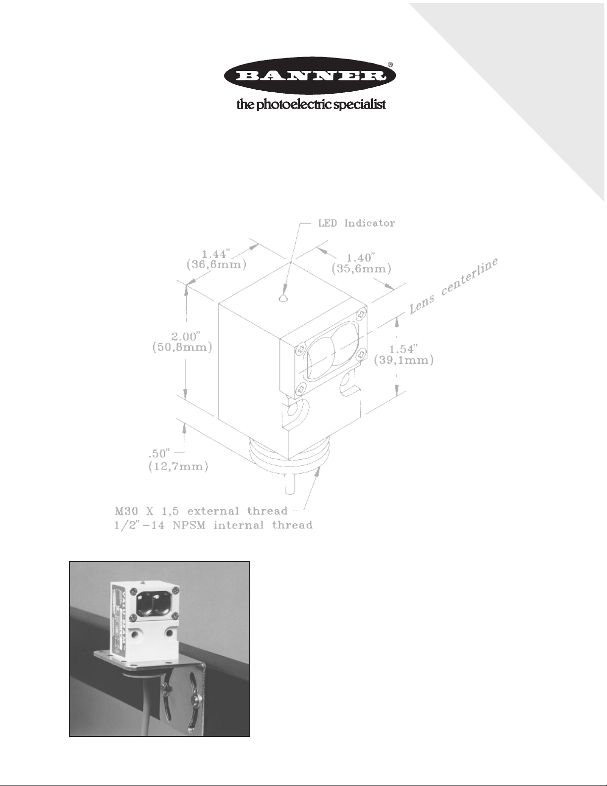
VALU-BEAM sensors may be mounted from either the front or the
rear using their two through-mounting holes, or by the outside
threads of their M30x1.5 threaded base (mounting nut supplied),
making them ideal for conveyor and other production line applications. A versatile 2-axis steel accessory mounting bracket (model
SMB900) simplifies mounting and alignment. Model SMB30SM
swivel-mount bracket offers the ultimate in flexibility and convenience. The bases of standard VALU-BEAMs have a 1/2" NPS
integral internal conduit thread, and are supplied with a 6-foot
PVC-covered cable. Models with a NEMA-4 rated quick-disconnect connector (QD models) are available optionally.
All VALU-BEAM sensors have an easily-visible top-mounted red
LED indicator to assist in alignment and system monitoring. On
SMA915, SMB915, SMW915, and SMA990 Series VALUBEAMs, this indicator lights whenever the sensor "sees" its
modulated light source. On SM2A912 Series 2-wire sensors, the
LED lights whenever the load is energized. SM912 Series sensors
have Banner's exclusive, patented "AID" system (Alignment Indicating Device, US patent #4356393) which lights the indicator
LED whenever the sensor "sees" its modulated light source, and
also pulses the LED at a rate proportional to the received light signal
strength. This feature greatly simplifies alignment: in most situations, alignment becomes simply a matter of positioning the sensor
for maximum LED pulse rate.
VALU-BEAMs offer a choice of light or dark operate in the same
sensor. This is done via a rear panel control or, in the relay output
units, by offering both N/O and N/C output relay contacts.
WARNING VALU-BEAM photoelectric presence sensors do NOT include the self-checking redundant circuitry necessary
to allow their use in personnel safety applications. A sensor failure or malfunction can result in either an energized or a de-energized
sensor output condition.
!
ANSI machine safety standards for point-of-operation guarding devices. No other Banner sensors or controls are designed to meet these standards, and
they must NOT be used as sensing devices for personnel protection.
WARRANTY: Banner Engineering Corporation warrants its products to be free from defects for one year. Banner Engineering Corporation will repair or replace,
free of charge, any product of its manufacture found to be defective at the time it is returned to the factory during the warranty period. This warranty does not
cover damage or liability for the improper application of Banner products. This warranty is in lieu of any other warranty either expressed or implied.
Never use these products as sensing devices for personnel protection. Their use as safety devices may create an unsafe condition which
could lead to serious injury or death.
Only MACHINE-GUARD and PERIMETER-GUARD Systems, and other systems so designated, are designed to meet OSHA and
2
Page 3
VALU-BEAM Sensors
*NOTE: Emitter voltage range is 10-250V ac or dc
Series Model Sensing Mode Range Operating Voltage* Page
912 Series SMA91E & SM91R Opposed: long range 200 feet 10 to 30V dc* p. 5
Sensors with
infinite-life
solid-state output
relay
SMA91E & SM2A91R Opposed: long range 200 feet 24 to 250V ac* p. 5
SMA91ESR & SM91RSR Opposed: short range 10 feet 10 to 30V dc* p. 5
SMA91ESR & SM2A91RSR Opposed: short range 10 feet 24 to 250V ac* p. 5
SM912LV Retroreflective: visible beam 30 feet 10 to 30V dc p. 5
SM2A912LV Retroreflective: visible beam 30 feet 24 to 250V ac p. 5
SM912LVAG Retroreflective: polarized beam 15 feet 10 to 30V dc p. 5
SM2A912LVAG Retroreflective: polarized beam 15 feet 24 to 250V ac p. 5
SM912D Diffuse (proximity): long range 30 inches 10 to 30V dc p. 6
SM2A912D Diffuse (proximity): long range 30 inches 24 to 250V ac p. 6
SM912DSR Diffuse (proximity): short range 15 inches 10 to 30V dc p. 6
SM2A912DSR Diffuse (proximity): short range 15 inches 24 to 250V ac p. 6
SM912CV Convergent beam: visible red 1.5-inch focus 10 to 30V dc p. 6
SM2A912CV Convergent beam: visible red 1.5-inch focus 24 to 250V ac p. 6
SM912C Convergent beam: infrared 1.5-inch focus 10 to 30V dc p. 7
SM2A912C Convergent beam: infrared 1.5-inch focus 24 to 250V ac p. 7
SMA91EF & SM91RF Opposed fiber optic: glass fibers see specs 10 to 30V dc* p. 6
SMA91EF & SM2A91RF Opposed fiber optic: glass fibers see specs 24 to 250V ac* p. 6
SM912F Fiber optic: glass fibers see specs 10 to 30V dc p. 7
SM2A912F Fiber optic: glass fibers see specs 24 to 250V ac p. 7
915 Series SMA91E & SMW95R Opposed: long range 200 feet 12 to 28V ac/dc* p. 11
SMA91E & SMA95R Opposed; long range 200 feet 90 to 130V ac* p. 11
Sensors with
SPDT
electromechanical
output relay
SMA91E & SMB95R Opposed: long range 200 feet 210 to 250V ac* p. 11
SMA91ESR & SMW95RSR Opposed: short range 10 feet 12 to 28V ac/dc* p. 11
SMA91ESR & SMA95RSR Opposed: short range 10 feet 90 to 130V ac* p. 11
SMA91ESR & SMB95RSR Opposed: short range 10 feet 210 to 250V ac* p. 11
SMW915LV Retroreflective: visible beam 30 feet 12 to 28V ac/dc p. 11
SMA915LV Retroreflective: visible beam 30 feet 90 to 130V ac p. 11
SMB915LV Retroreflective: visible beam 30 feet 210 to 250V ac p. 11
SMW915LVAG Retroreflective: polarized beam 15 feet 12 to 28V ac/dc p. 11
SMA915LVAG Retroreflective: polarized beam 15 feet 90 to 130V ac p. 11
SMB915LVAG Retroreflective: polarized beam 15 feet 210 to 250V ac p. 11
SMW915D Diffuse (proximity): long range 30 inches 12 to 28V ac/dc p. 12
SMA915D Diffuse (proximity): long range 30 inches 90 to 130V ac p. 12
SMB915D Diffuse (proximity): long range 30 inches 210 to 250V ac p. 12
SMW915DSR Diffuse (proximity): short range 15 inches 12 to 28V ac/dc p. 12
SMA915DSR Diffuse (proximity): short range 15 inches 90 to 130V ac p. 12
SMB915DSR Diffuse (proximity): short range 15 inches 210 to 250V ac p. 12
SMW915CV Convergent: visible red 1.5-inch focus 12 to 28V ac/dc p. 12
SMA915CV Convergent: visible red 1.5-inch focus 90 to 130V ac p. 12
SMB915CV Convergent: visible red 1.5-inch focus 210 to 250V ac p. 12
SMW915F Fiber optic: glass fibers see specs 12 to 28V ac/dc p. 13
SMA915F Fiber optic: glass fibers see specs 90 to 130V ac p. 13
SMB915F Fiber optic: glass fibers see specs 210 to 250V ac p. 13
SMW915FP Fiber optic: plastic fibers see specs 12 to 28V ac/dc p. 13
SMA915FP Fiber optic: plastic fibers see specs 90 to 130V ac p. 13
SMB915FP Fiber optic: plastic fibers see specs 210 to 250V ac p. 13
990 Series SMA91E & SMA99R Opposed: long range 200 feet* p. 15
Sensors with
built-in 6-digit
totalizing counter
SMA91ESR & SMA99RSR Opposed: narrow beam 10 feet* p. 15
SMA990LV Retroreflective: visible beam 30 feet p. 15
SMA990LVAG Retroreflective: polarized beam 15 feet p. 15
SMA990LT Retroreflective: infrared beam 30 feet p. 16
(used for "people counting")
SMA990CV Convergent beam: visible red 1.5-inch focus p. 16
SMA990F Fiber optic: glass fibers see specs p. 17
SMA990FP Fiber optic: plastic fibers see specs p. 16
All 990 Series
sensors operate
from 10 to 250V ac
or 12 to 115V dc
3
Page 4
VALU-BEAM 912 Series Sensors
dc sensor specifications
SUPPLY VOLTAGE: 10 to 30V dc at 20mA, exclusive of load
(except for SMA91E, ESR, and EF emitters, which operate from 10 to
250V ac or dc, 10mA max.).
OUTPUT CONFIGURATION: one current sourcing (PNP) and one
current sinking (NPN) open-collector transistor.
OUTPUT RATING: 250mA continuous, each output. Off-state
leakage current less than 10 microamps. Output saturation voltage:
for PNP output, <1 volt at 10mA and <2 volts at 250mA; for NPN
output, <200 millivolts at 10mA and <1volt at 250mA.
OUTPUT PROTECTION: protected against false pulse on powerup, inductive load transients, power supply polarity reversal, and
continuous overload or short circuit of outputs.
RESPONSE TIME: 4 milliseconds ON, 4 milliseconds OFF (except
reciever-only units, which are 8 ms ON and 4 ms OFF). Independent
of signal strength. 100 millisecond delay on power-up (outputs nonconducting during this time).
REPEATABILITY OF RESPONSE: see individual sensor specs.
Independent of signal strength.
CONSTRUCTION: reinforced VALOX
lated, molded acrylic lenses, stainless steel hardware. Meets NEMA
standards 1, 2, 3, 3S, 4, 4X, 12, and 13.
CABLE: 6' of PVC-jacketed cable standard; 2-conductor (emitters) or
4-conductor. Quick-disconnect (QD) models are available optionally.
Model MBCC-412 4-conductor cable for dc "QD" models must be
purchased separately. DC "QD" emitters use cable model MBCC-312.
"QD" cable is purchased separately; see pages 18 and 19.
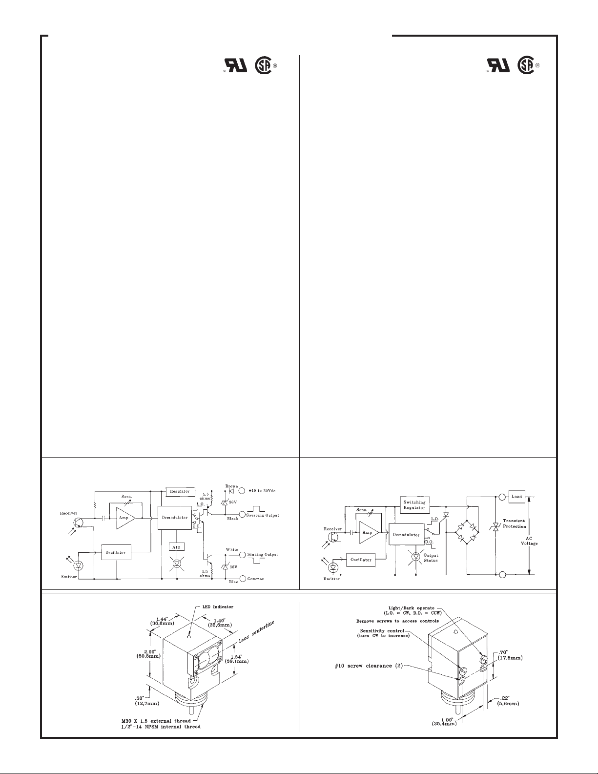
ADJUSTMENTS: LIGHT/DARK OPERATE select switch and
SENSITIVITY control potentiometer, both located on rear of sensor.
INDICATOR LED: exclusive, patented Alignment Indicating Device system (AID™, US patent #4356393) lights a top-mounted red
LED indicator whenever the sensor sees a "light" condition, with a
superimposed pulse rate proportional to the light signal strength (the
stronger the signal, the faster the pulse rate).
OPERATING TEMPERATURE RANGE: -20 to +70 degrees C
(-4 to +158 degrees F).
®
housing, totally encapsu-
ac sensor specifications
SUPPLY VOLTAGE: 24 to 250V ac (50/60Hz), except for SMA91E,
ESR, and EF emitters, which operate from 10 to 250V ac or dc.
OUTPUT CONFIGURATION: solid-state switching element.
OUTPUT RATING: min. load current 10mA; max. steady-state load
capability 750mA to 50°C ambient (122°F), 500mA to 70°C ambient
(158°F). Inrush capability 4 amps for 1 sec. (non-repetitive). Off-state
leakage current less than 1.7mA rms. On-state voltage drop ≤5 volts
rms at 750mA load, ≤10 volts rms at 15mA load.
OUTPUT PROTECTION: protected against false pulse on powerup and inductive load transients.
RESPONSE TIME: 8 milliseconds ON, 8 milliseconds OFF (except
receiver-only units, which are 8 ms ON and 4 ms OFF). OFF time does
not include load response of up to 1/2 ac cycle (8.3 milliseconds).
Independent of signal strength. Response time specification of the load
should be considered when important. 300-millisecond delay on
power-up (outputs are non-conducting during this time).
REPEATABILITY OF RESPONSE: see individual sensor specs.
Does not take into consideration "off" response time variation of up to
1/2 ac cycle (8.3ms) and load response time. Independent of signal
strength.
CONSTRUCTION: reinforced VALOX
lated, molded acrylic lenses, stainless steel hardware. Meets NEMA
standards 1, 2, 3, 3S, 4, 4X, 12, and 13.
CABLE: 6' of PVC-jacketed 2-conductor cable standard. Three-pin
quick-disconnect (QD) models are available optionally (one connector
pin goes unused). Model MBCC-312 3-conductor cable for "QD"
models must be purchased separately (see pages 18 and 19).
ADJUSTMENTS: LIGHT/DARK OPERATE select switch and
SENSITIVITY control potentiometer, both located on rear of sensor.
INDICATOR LED: top-mounted red LED indicator lights when
output is conducting. Model SMA91E emitter has a visible-red "tracer
beam" which indicates "power on" and enables easy "line-of-sight"
alignment.
OPERATING TEMPERATURE RANGE: -20 to +70 degrees C
(-4 to +158 degrees F).
®
housing, totally encapsu-
Functional Schematic: SM912 Series DC Sensors
Dimension Drawing,
Front View
4
Functional Schematic: SM2A912 Series AC Sensors
Rear View
Page 5
VALU-BEAM 912 Series Sensors
Sensing Mode
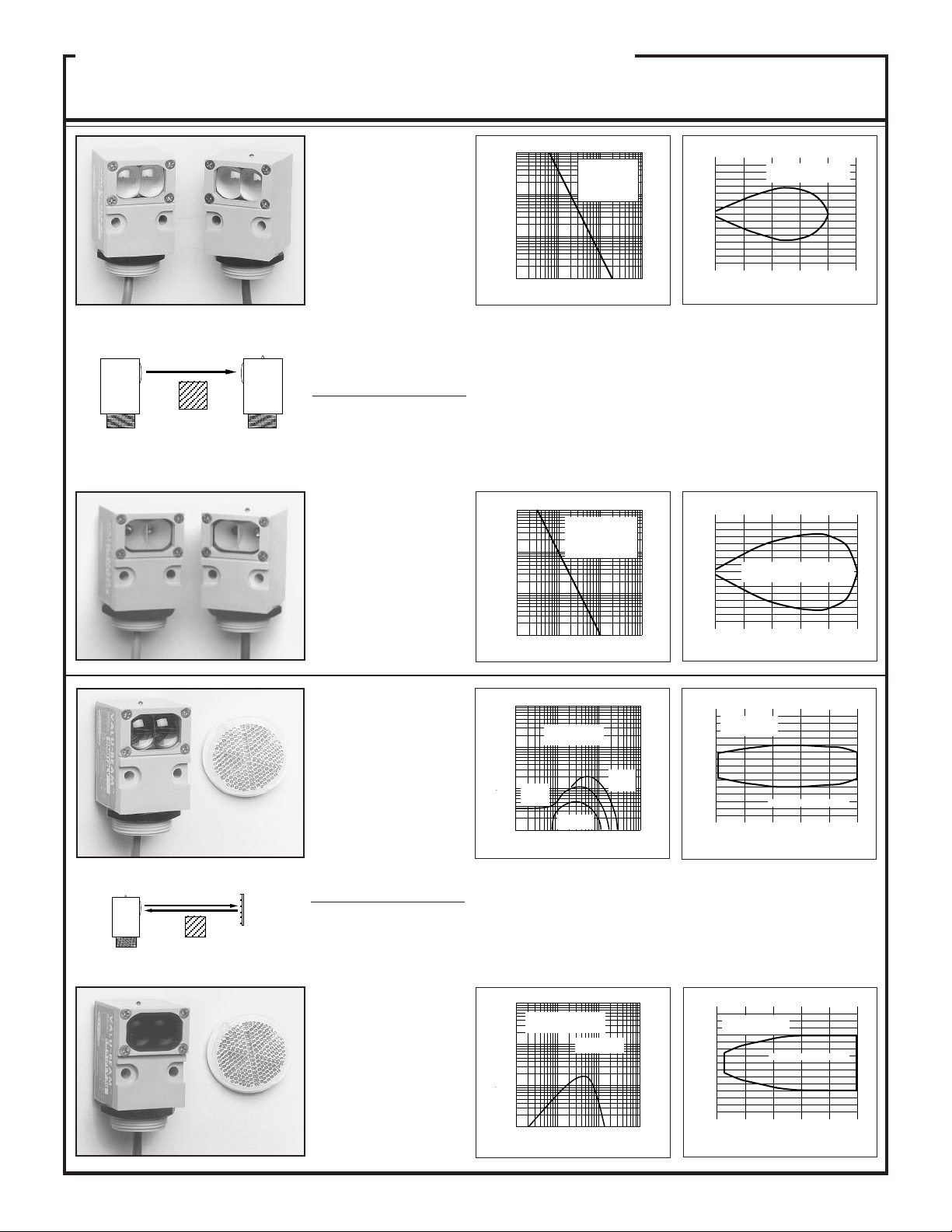
OPPOSED Mode
EMITTER
OBJECT
Repeatability: 1.0ms (all models)
RECEIVER
SMA91E & SM91R
Voltage: 10 to 30V dc,
("E": 10-250V ac/dc)
Range: 200 feet (60 m)
Response: 8ms on/4 off
Beam: infrared, 880nm;
visible red tracer beam
Effective beam: 0.5" dia.
SMA91E &SM2A91R
Voltage: 24 to 250V ac,
("E": 10-250V ac/dc)
Range: 200 feet (60 m)
Response: 8ms on/4 off
Beam: infrared, 880nm
Effective beam: 0.5" dia.
SMA91ESR &
SM91RSR
Voltage: 10 to 30V dc,
("ESR": 10-250V ac/dc)
Range: 10 feet (3 m)
Response: 8ms on/4 off
Beam: infrared, 880nm
Effective beam: 0.14" dia.
SMA91ESR &
SM2A91RSR
Voltage: 24 to 250V ac
Range: 10 feet (3 m)
Response: 8ms on/4 off
Beam: infrared, 880nm
Effective beam: 0.14" dia.
Excess GainModels
1000
E
X
C
100
E
S
S
G
10
A
I
I
N
1
1 FT 10 FT 100 FT 1000 FT
SMA91E &
SM91R,
SMA91E &
SM2A91R
DISTANCE
Beam Pattern
60
40
I
20
N
C
0
H
E
20
S
40
60
0
SMA91E/SM91R,
SMA91E/SM2A91R
50 100 150 200 250
OPPOSED DISTANCE--FEET
Opposed mode sensors have higher excess gain than other models, and
therefore should be used whenever possible. The small size of these
sensors makes them ideal for many conveyor applications, and their small
effective beam size (particularly of the ESR/RSR models) enables them
to reliably detect relatively small objects. VALU-BEAM opposed mode
sensors have a visible red "tracer beam" which greatly simplifies sensor
alignment. ESR/RSR models have a wide beam angle for very forgiving
alignment within the 10 foot range. E/R models have a narrow beam
spread and should be used when it is important to minimize optical
"crosstalk" between adjacent emitter-receiver pairs at close range in
multiple sensor arrays.
1000
E
X
C
100
E
S
S
G
A
10
I
I
N
1
.1 FT 1 FT 10 FT
SMA91ESR &
SM91RSR,
SMA91ESR &
SM2A91RSR
DISTANCE
100 FT
I
N
C
H
E
S
12
8
4
SMA91ESR/SM91RSR,
0
SMA91ESR/SM2A91RSR
4
8
12
2 468100
OPPOSED DISTANCE--FEET
RETROREFLECTIVE
RETROREFLECTIVE TARGET
OBJECT
Repeatability:
1.3ms (dc models); 2.6ms (ac models)
SM912LV
Voltage: 10 to 30V dc
Range: 6 inches to
30 feet (9 m)
Response: 4ms on/off
Beam: visible red, 650nm
SM2A912LV
Voltage: 24 to 250V ac
Range: 6 inches to
30 feet (9 m)
Response: 8ms on/off
Beam: visible red, 650nm
SM912LVAG
(anti-glare filter)
Voltage: 10 to 30V dc
Range: 1 to 15 feet (4,5 m)
Response: 4ms on/off
Beam: visible red, 650nm
(with polarizing filter)
SM2A912LVAG
(anti-glare filter)
Voltage: 24 to 250V ac
Range: 1 to 15 feet (4,5 m)
Response: 8ms on/off
Beam: visible red, 650nm
(with polarizing filter)
1000
SM912LV
E
X
C
E
S
S
G
A
I
I
N
SM912LV,
SM2A912LV
100
with 3"
with 1"
10
reflector
(BRT-1)
with
BRT-T tape
1
.1 FT 1 FT 10 FT 100 FT
DISTANCE
reflector
(BRT-3)
6
SM2A912LV
4
I
2
N
C
0
H
E
2
S
4
6
6 121824300
DISTANCE TO REFLECTOR--FEET
with BRT-3 REFLECTOR
A visible-red light beam reduces the potential for false signals from highly
reflective objects ("proxing") and simplifies alignment. AG (anti-glare) models
polarize the emitted light and filter out unwanted reflections, making their use
possible in applications otherwise unsuited to retroreflective sensing (when
reduced excess gain is acceptable). Maximum range with "LV" units is attained
when using the model BRT-3 3" corner cube reflector. For details on retroreflective target materials, see the Banner product catalog.
1000
E
X
C
100
E
S
S
G
A
10
I
I
N
1
.1 FT
SM912LVAG,
SM2A912LVAG
with one BRT-3
3" retroreflector
1 FT 10 FT 100 FT
DISTANCE
3
SM912LVAG
SM2A912LVAG
2
I
1
N
C
0
H
E
1
S
2
3
36912150
DISTANCE TO REFLECTOR--FEET
with BRT-3 REFLECTOR
5
Page 6
)
)
%
VALU-BEAM 912 Series Sensors
n
Sensing Mode
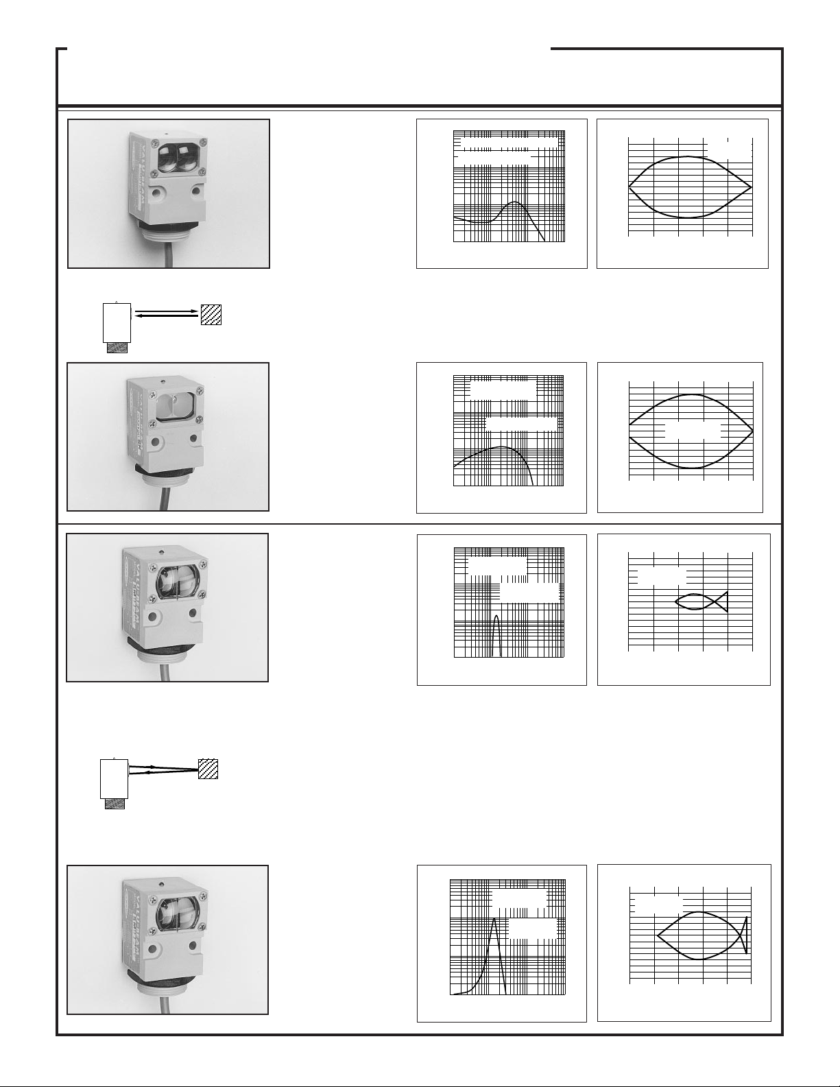
DIFFUSE Mode
OBJECT
Models
SM912D
Voltage: 10 to 30V dc
Range: 30 inches (76 cm)
Response: 4ms on/off
Beam: infrared, 880nm
SM2A912D
Voltage: 24 to 250V ac
Range: 30 inches (76 cm)
Response: 8ms on/off
Beam: infrared, 880nm
Repeatability:
1.3ms (dc models);
2.6ms (ac models)
SM912DSR
Voltage: 10 to 30V dc
Range: 15 inches (38cm)
Response: 4ms on/off
Beam: infrared, 880nm
SM2A912DSR
Voltage: 24 to 250V ac
Range: 15 inches (38cm)
Response: 8ms on/off
Beam: infrared, 880nm
Excess Gain
1000
SM912D, SM2A912D
E
(Range based on 90%
X
reflectance white test card
C
100
E
S
S
G
10
A
I
I
N
1
.1 IN 1 IN 10 IN 100 IN
DISTANCE
Beam Pattern
.75
.50
I
.25
N
C
0
H
E
.25
S
.50
.75
6 121824300
DISTANCE TO 90% WHITE TEST CARD--INCHES
SM912D
SM2A912D
These sensors operate by detecting the reflection of their own light from
the object being sensed, and therefore require no special reflectors. "DSR"
models have better response than "D" models to objects within 3 inches of
the sensor. "DSR" models should be used when it is necessary to minimize
sensor response to background objects.
1000
SM912DSR,
SM2A912DSR
E
X
100
C
E
S
S
G
A
I
I
N
(Range base on 90%
reflectance white test card
10
1
.1 IN 1 IN 10 IN 100 IN
DISTANCE
.75
.50
I
.25
N
C
0
H
E
.25
S
.50
.75
DISTANCE TO 90% WHITE TEST CARD--INCHES
SM912DSR
SM2A912DSR
36912150
CONVERGENT Mode
OBJECT
SM912CV
Voltage: 10 to 30V dc
Focus at 1.5" (38 mm)
Response: 4ms on/off
Beam: visible red, 650nm
SM2A912CV
Voltage: 24 to 250V ac
Focus at 1.5" (38 mm)
Response: 8ms on/off
Beam: visible red, 650nm
Repeatability:
1.3ms (dc models);
2.6ms (ac models)
SM912C
Voltage: 10 to 30V dc
Focus at 1.5" (38 mm)
Response: 4ms on/off
Beam: infrared, 880nm
SM2A912C
Voltage: 24 to 250V ac
Focus at 1.5" (38 mm)
Response: 8ms on/off
Beam: infrared, 880nm
1000
SM912CV,
E
SM2A912CV
X
C
100
E
S
S
G
10
A
I
I
N
1
.1 IN 1 IN 10 IN 100 IN
(Range based on 90
reflectance white test
card)
DISTANCE
.09
SM912CV
.06
SM2A912CV
I
.03
N
C
0
H
E
.03
S
.06
.09
1.0 1.5 2.0 2.5
.50
DISTANCE TO 90% WHITE TEST CARD--INCHES
VALU-BEAM SM912CV and SM2A912CV visible red convergent sensors
(above) produce a precise .06" diameter sensing spot at a focus point 1.5" in
front of the sensor lens. Due to their very narrow depth of field, they excel at
detecting small objects only a fraction of an inch away from backgrounds.
They are also ideal for some high-contrast color-registration applications.
Their visible red sensing beam simplifies alignment.
Models SM912C and SM2A912C (below) are infrared convergent beam sensors.
Operating voltages, response times, repeatability, and focus distance are the same
as for the SM912CV and SM2A912CV. The SM912C and SM2A912C, however,
have much higher excess gain and an infrared sensing beam for highly reliable
sensing of objects of low reflectivity.
1000
SM912C,
E
X
100
C
E
S
S
G
10
A
I
I
N
1
.1 IN 1 IN 10 IN 100 IN
SM2A912C
(Range based o
90% reflectance
white test card)
DISTANCE
.09
SM912C
SM2A912C
.06
I
.03
N
C
0
H
E
.03
S
.06
.09
1.2 1.8 2.4 3.0
.60
DISTANCE TO 90% WHITE TEST CARD--INCHES
6
Page 7

VALU-BEAM 912 Series Sensors
s
s
r
F
Sensing Mode
OPPOSED FIBER OPTIC
MODE (glass fibers)
EMITTER
OBJECT
FIBER OPTIC Mode
OPPOSED
OBJECT
RETRO
OBJECT
RETROREFLECTIVE TARGET
DIFFUSE
RECEIVER
OBJECT
Models Excess Gain
SMA91EF &
SM91RF
Voltage: 10 to 30V dc
("EF": 10-250V ac/dc)
Range: see E.G. curves
Response: 8ms on/4 off
Beam: infrared, 880nm
Repeatability:
1.0ms (all models)
SMA91EF &
SM2A91RF
Voltage: 24 to 250V ac
("EF": 10-250V ac/dc)
Range: see E.G. curves
Response: 8ms on/4 off
Beam: infrared, 880nm
SM912F
Voltage: 10 to 30V dc
Range: see E.G. curves
Response: 4ms on/off
Beam: infrared, 880nm
SM2A912F
Voltage: 24 to 250V ac
Range: see E.G. curves
Response: 8ms on/off
Beam: infrared, 880nm
Repeatability:
1.3ms (dc models);
2.6ms (ac models)
Fiber optic sensing is often
the answer when, due to space
or environmental limitations,
the sensor itself cannot be
placed at the actual sensing
position. These sensors' powerful modulated infrared
beam is compatible with all
Banner glass fiber optics in
the opposed, retroreflective,
and diffuse sensing modes
(see Banner product catalog).
Sensor/fiber interface is waterproof to maintain complete
sensing system moisture rejection.
1000
E
X
100
C
E
S
S
G
10
A
I
I
N
with
IT13S
fibers
1
.1 FT 1 FT 10 FT 100 FT
These opposed mode fiber optic emitter-receiver pairs are used where the
separation between emitting and receiving fibers is greater than a few feet, or
where it is inconvenient to run both fibers from a single VALU-BEAM sensor.
These models have a watertight o-ring sealed sensor/fiber interface, and are
compatible with all Banner glass fiber optic assemblies (see product catalog).
1000
SM912F, SM2A912F
E
X
100
C
E
S
S
G
10
A
I
I
N
IT13S fibers
1
.1 IN 1 IN 10 IN
1000
SM912F, SM2A912F
E
X
100
C
E
S
S
G
10
A
I
I
N
E
X
C
E
S
S
G
A
I
I
N
with L9 len
and BT13S
fibers
1
.1 FT 1 FT 10 FT 100 FT
1000
SM912F,
SM2A912F
100
10
with
BT13S
fibers
1
.1 IN 1 IN 10 IN 100 IN
SMA91EF &
SM91RF,
SMA91EF &
with
IT23S
SM2A91RF
and
L9
lenses
with
IT23S
fibers
DISTANCE
Opposed
mode,
glass fibers
IT23S fibers
DISTANCE
Retroreflective
mode, w/BRT-3 3"
target
with L16F len
and BT13S
fibers
DISTANCE
Diffuse mode
Range based on 90%
reflectance white test card
with
BT23S
fibers
DISTANCE
with
IT23S &
L16F
lenses
100 IN
Beam Pattern
SMA91EF/SM91RF,
SMA91EF/SM2A91RF
12
8
I
4
N
C
H
E
S
3
2
I
1
N
C
H
E
1
S
2
3
I
N
C
H
E
S
.075
.050
I
.025
N
C
H
E
.025
S
.050
.075
DISTANCE TO 90% WHITE TEST CARD--INCHES
IT23S fibers
0
with L9 lenses
4
8
12
8 162432400
OPPOSED DISTANCE--FEET
SM912F, SM2A912F
0
opposed mode
4 8 12 16 200
OPPOSED DISTANCE --INCHES
6
4
2
0
with L9 lens with L16F lens
2
4
6
4 8 12 16 200
DISTANCE TO REFLECTOR--FEET
.1
SM912F, SM2A912F
0
.1
.3 .60
IT23S fibers
with L16F lenses
IT23S fibers
IT13S fibers
SM912F, SM2A912
Retroreflective mode,
BT13S fiber, BRT-3 reflecto
BT23S
BT13S
Diffuse mode
1.2 1.5
.9
7
Page 8

c
y
c
e
c
c
e
s
c
c
VALU-BEAM 912 Series Sensors
Hookup Diagrams for dc SM912 Series Sensors
For emitter hookup, see below.
NOTE: each output has a maxi-
mum load capacity of 250mA.
Hookup to dc Relay or
Solenoid (using sinking output)
The diagram below shows hookup of a dc VALUBEAM to a dc load using the sensor's sinking
output, which is rated at 250mA maximum.
The BLACK
wire is not
used.
10 - 30V d
BROWN BLUE
WHITE
LOAD
BLACK
Hookup to dc Relay or
Solenoid (using sourcing output)
The diagram below shows hookup of a dc VALUBEAM to a dc load using the sensor's sourcing
output, which is rated at 250mA maximum.
The WHITE
wire is not
used.
Hookup to Programmable Controller
(sinking output)
This diagram shows hookup of a dc VALU-BEAM to a programmable
controller requiring a current sink, using the sensor's sinking output. The
BLACK wire
is not used.
Hookup shown is
typical for all
inputs.
BLACK
BLACK wire
is not used
WHITE
(sinking output)
BROWN
+10 - 30V d
BLUE
(common)
Hookup shown is
typical for all inputs
1
2
3
4
5
6
7
8
dc+
dc com
P
r
I
o
N
g.
P
U
C
T
t
S
r
l.
Hookup to a Logic Gate
The diagram below shows hookup of a dc VALUBEAM to a logic gate. A logic zero (0 volts dc)
is applied to the gate input when the VALUBEAM output is energized. When de-energized,
a logic one is applied. The logic supply negative
must be common to the VALU-BEAM supply
10 - 30V d
BROWN BLUE
BLACK
WHITE
LOAD
negative.
BLACK
BLACK
wire
is not used
* Use pullup resistor to logic suppl
BROWN
+10 -30V d
WHITE (sinking)
output, 150mA max.
BLUE
(common)
+5V to 30V dc
logic supply
*
Hookup to Programmable Controller
(sourcing output)
This diagram shows hookup of a dc VALU-BEAM to a programmable
controller requiring a current source, using the sensor's sourcing output. The
WHITE wire is not used.
Hookup shown is
typical for all inputs
Hookup shown is
typical for all
inputs.
WHITE
White wire
is not used
BLACK
(sourcing
output)
BROWN
+10 - 30V d
BLUE
(common)
1
2
3
4
5
6
7
8
dc+
dc com
(-) dc
P
r
I
o
N
g.
P
U
C
T
t
S
r
l.
Hookup to B Series Logic (MRB chassis)
The current sinking output (white
wire) of the VALU-BEAM is shown
7
6
8
5
1
4
23
+15V dc
7
6
B Serie
8
5
1
4
Module
23
120 Vac
MRB
WHITE
BROWN
BLUE
BLACK wir
is not used
connected to the input (pin 5) of a B
Series module. It may be connected
to the auxiliary input (pin 3) if desired. (See description of module
for function of aux. input). Any B
BLACK
Series module may be used. Banner PLUG LOGIC modules may
also be used (contact the factory for
further information).
Hookup to MAXI-AMP Logic Module
The current sinking output(s) of VALU-BEAM sensors may be connected directly to the input of CL Series
MAXI-AMP modules. A MAXI-AMP which is powered by ac voltage offers a dc supply with the capacity
to power one VALUBEAM sensor (see
hookup diagram).
When emitter/receiver
pairs are used, the
emitter should be powered from a separate
power source.
54
CL3RA
CL3RB
76
CL5RA
8
CL5RB
BROWN
WHITE
9 1011 1 2 3
BLUE
BLACK wire
is not used
BLACK
Hookup to MICRO-AMP Logic (MPS-15 chassis)
The current sinking (white) output of the VALU-BEAM is shown connected to the primary input (pin 7) of a MICRO-AMP logic module. It may
be connected, instead, to the other inputs (see logic module descriptions in
the Banner product catalog). The following logic modules may be used:
WHITE
NO
Micro-
7
6
Amp
Logic
NC
5
BROWN
4
3
BLUE
Relay
N
C
C
8
1
2
MODEL MPS-15
120
VacNO
Emitter Hookup
(ac or dc power)
L1 L2
MA4-2 One-shot
MA5 On/off delay
MA4G 4-input "AND"
MA4L Latch
BLACK
BLACK wir
is not used
10 to 250V ac or V d
SMA91E
SMA91EF
SMA91ESR
+
Brown
Blue
8
Page 9

c
c
c
s
c
VALU-BEAM 912 Series Sensors
Hookup Diagrams for ac SM2A912 Series Sensors
NOTE: maximum load capacity
of output is 500mA.
Basic ac Hookup
For emitter hookup, see preceding page.
VALU-BEAM 2-wire ac sensors wire in series
with an appropriate load. This combination, in
turn, wires across the ac line.
L1 L2
24 to 250V a
I
off = <1.7mA
LOAD
These sensors operate in the range of 24 to
250V ac, and may be programmed for either
normally open (N.O.) or normally closed (N.C.)
operation by way of the light-dark operate
switch on the back of the sensor. A 2-wire ac
sensor may be connected exactly like a mechanical limit switch.
The sensor remains powered when the load is
"off" by a residual current which flows through
the load. The off-state leakage current (I
always less than 1.7mA. The effect of this
leakage current depends on the characteristics
of the load. The voltage which appears across
the load in the off-state is equal to the leakage
current of the sensor multiplied by the resistance of the load:
V
= 1.7mA x R
off
load
If this resultant off-state voltage is less than the
guaranteed turn-off voltage of the load, then the
interface is direct. If the off-state voltage
causes the load to stay "on", then an artificial
load resistor must be connected in parallel with
the load to lower the effective resistance. Most
loads, including most programmable controller
inputs, will interface to 2-wire sensors with
1.7mA leakage current without an artificial
load resistor. These sensors are not polarity
sensitive: all hookups are without regard to
wire color.
WARNING: VALU-BEAM 2-wire ac sensors
will be destroyed if the load becomes a short
circuit!!
) is
off
Connection to
Programmable Controllers
Hookup shown is typical for
all inputs.
L1 L2
ac neutralac "hot"
Vac
Hookup shown
is typical for
all inputs
1
P
2
r
I
3
o
N
4
g.
P
5
U
6
C
T
7
r
S
8
t
neutral
l.
AC Sensors in Series
Multiple 2-wire ac VALU-BEAMs may be wired
together in series for "AND" or "NOR" logic functions. The maximum number of sensors which may
be wired in series to a load depends upon the level
of the line voltage and the switching characteristics
of the load. Each sensor connected in series adds an
amount of voltage drop across the load. The
amount of voltage drop that each sensor adds
depends upon the current demand of the load. Each
sensor in series adds approximately 5 volts drop
across a 500mA load. A 15mA load will see about
a 10 volt drop from each sensor added in series. To
determine compatibility, compare the resultant onstate voltage across the load against the load's
guaranteed turn-on voltage level (from the
manufacturer's specifications).
AC Sensors in Parallel
Multiple 2-wire ac VALU-BEAMs may be wired
in parallel to a load for "OR" or "NAND" logic
functions. With sensors wired in parallel, the offstate leakage current through the load is equal to the
sum of the leakage currents required by the individual sensors. Consequently, loads with high
resistance like small relays and solid state inputs
may require artificial load resistors.
AC VALU-BEAMs wired together in parallel will
not cause momentary drop-out of the load, as is
experienced when wiring in parallel with contacts
(see below). However, it is likely that the powerup delay feature will cause a momentary drop-out
of the load if an ac VALU-BEAM is wired in
parallel with a different brand or model of 2-wire
sensor. Contact the Banner applications group to
verify compatibility.
AC Sensors in Series
with Contacts
When 2-wire ac sensors are connected in series
with mechanical limit switch or relay contacts, the
sensor will receive power to operate only when all
of the contacts are closed. The false-pulse protection circuit of the sensor will cause a 0.3 second
delay between the time the contacts close and the
time that the load can energize.
L1 L2
24 to 250V a
LOAD
0.3 second delay
when contact close
L1 L2
24 to 250V a
LOAD
Most non-compatibility of series-connected sensors with loads occurs in low-voltage applications
(e.g. 12, 24, or 48V ac circuits) where the on-state
voltage drop across the load is a significant percentage of the supply voltage. The power-up inhibit time (up to 300 milliseconds per sensor) is
also additive.
L1 L2
24 to 250V a
<1.7mA
LOAD
I
off = <3.4mA
<1.7mA
AC Sensors in Parallel
with Contacts
When 2-wire ac sensors are connected in parallel
with mechanical switch or relay contacts, the
sensor loses the current it needs to operate while
any contact is closed. When all of the contacts
open, the sensor's 0.3 second power-up delay
may cause a momentary drop-out of the load.
L1
24 to 250V ac
LOAD
0.3 second delay
when contact opens
L2
9
Page 10

VALU-BEAM 915 Series
Sensors with Electromechanical Relay Output
VALU-BEAM 915 Series sensors have all of the ruggedness
and versatility of VALU-BEAM sensors, but with an internal
single-pole, double-throw electromechanical output relay.
SMW915 Series sensors operate from 12-28V ac or dc. SMA915 Series sensors operate from 90 to 130V ac; SMB915 Series
sensors from 210 to 250V ac. Remaining specifications (below)
are identical for all three series.
Specifications: SMW915, SMA915, and SMB915
Series VALU-BEAM Sensors
SUPPLY VOLTAGE (SMW915 series): 12 to 28V ac or dc at 50mA
maximum, exclusive of load, except for SMA91E and ESR emitters,
which operate from 10-250V ac (50-60Hz) or dc (10mA max.).
SUPPLY VOLTAGE (SMA915 series): 90 to 130V ac (50-60Hz),
20mA maximum, exclusive of load, except for SMA91E and ESR
emitters, which operate from 10-250V ac (50-60Hz) or dc (10mA
max.).
SUPPLY VOLTAGE (SMB915 series): 210 to 250V ac (50-60Hz),
20mA maximum, exclusive of load, except for SMA91E and ESR
emitters, which operate from 10-250V ac (50-60Hz) or dc (10mA
max.).
OUTPUT CONFIGURATION: one internal "form C" (single- pole
double-throw) electromechanical relay.
OUTPUT RATING: max. switching power (resistive load) = 150W,
600VA. Max. switching voltage (resistive load) = 250V ac or 30V dc
(120V ac max. per UL & CSA). Max. switching current (resistive
load) = 5A. Minimum voltage and current = 1 amp at 5V dc, 0.1 amp
at 24V dc. Peak switching voltage = 750Vac (transient suppression
recommended). Mechanical life of relay = 10,000,000 operations.
RESPONSE TIME: 20 milliseconds ON and OFF. 100-millisecond
delay on power-up (relay de-energized during this period).
®
CONSTRUCTION: reinforced black VALOX
capsulated, molded acrylic lenses, stainless steel hardware. Meets
NEMA standards 1, 2, 3, 3S, 4, 4X, 12, and 13.
CABLE: 6 feet of PVC-jacketed cable standard; 2-conductor for
emitters, 5-conductor for all other models. Quick-disconnect (QD)
models are available optionally. Model MBCC-512 5-conductor
cable for "QD" models must be purchased separately. Emitters use
3-conductor model MBCC-312 cable (purchase separately). See
pages 18 and 19 for "QD" cable information.
housing, totally en-
ADJUSTMENTS: SENSITIVITY control on rear of sensor allows
precise gain setting (turn clockwise to increase gain).
INDICATOR LED: top-mounted red LED indicator lights whenever the sensor sees a "light" condition. Models SMA91E and
SMA91ESR emitters have a visible-red "tracer beam" which indicates
"power on" and enables easy "line-of-sight" alignment.
OPERATING TEMPERATURE RANGE: -40 to +50 degrees C
(-40 to +122 degrees F).
Functional Schematic
* SMA units: 90-130V ac
SMB units: 210-250V ac
SMW units: 12-28V ac or dc
Dimension Drawing
10
Hookup Diagram
SMW915 or 95 models: 12-2 8V ac/dc
SMA915 or 95 models: 90-1 30V ac
SMB915 or 95 models: 210- 250V ac
BROWN BLUE
BLACK
(N.O. Contact)
YELLOW (Relay Common)
NOTE: relay contacts are rated at 5 amps
maximum (resistive load). See specifications.
For emitter hookup, see page 8.
WHITE
(N.C. Contact)
Page 11

0
0
VALU-BEAM 915 Series Sensors
OPPOSED Mode
EMITTER
OBJECT
RECEIVER
Models Excess Gain
SMA91E & SMW95R
Voltage: 12 to 28V ac/dc,
("E": 10-250V ac/dc)
Range: 200 feet (60m)
Effective beam: 0.5" dia.
SMA91E &
SMA95R or SMB95R
Voltage:
SMA95R 90 to 130V ac,
SMB95R 210 to 250V ac,
("E": 10-250V ac/dc)
Range: 200 feet (60m)
Effective beam: 0.5" dia.
All emitter/receiver pairs:
Response: 20ms on/off
Beam: infrared, 880nm
Visible red "tracer beam"
SMA91ESR &
SMW95RSR
Voltage: 12 to 28V ac/dc,
("ESR": 10-250V ac/dc)
Range: 10 feet (3m)
Effective beam: 0.14" dia.
SMA91ESR &
SMA95RSR or
SMB95RSR
Voltage:
SMA95RSR 90 to 130V ac,
SMB95RSR 210 to 250V ac,
("ESR": 10 to 250V ac/dc)
Range: 10 feet (3m)
Effective beam: 0.14" dia.
1000
E
X
C
100
E
S
S
G
10
A
I
I
N
1
1 FT 10 FT 100 FT 1000 FT
Opposed mode sensors have higher excess gain than other models, and
therefore should be used whenever possible. The small size of these
sensors makes them ideal for many conveyor applications, and their small
effective beam size (particularly of the ESR/RSR models) enables them
to reliably detect relatively small objects. ESR and RSR models also have
a wide beam angle for very forgiving alignment within the 10-foot range.
VALU-BEAM opposed mode sensors have a visible red "tracer beam"
which greatly simplifies sensor alignment. E and R models have a narrow
beam angle which allows receivers to be placed on relatively close centers
(at close range) in multiple sensor arrays.
100
E
X
C
100
E
S
S
G
A
10
I
I
N
1
.1 FT 1 FT 10 FT
SMA91E &
SMW95R or
SMA95R or
SMB95R
DISTANCE
SMA91ESR &
SMW95ESR or
SMA95ESR or
SMB95ESR
DISTANCE
100 FT
Beam PatternSensing Mode
SMA91E with SMW95R
60
or SMA95R or SMB95R
40
I
20
N
C
0
H
E
20
S
40
60
0
50 100 150 200 250
OPPOSED DISTANCE--FEET
12
8
I
4
N
C
0
H
E
4
S
8
12
2 468100
OPPOSED DISTANCE--FEET
SMA91ESR with
SMW95RSR or
SMA95RSR or
SMB95RSR
RETROREFLECTIVE
MODE
RETROREFLECTIVE TARGET
OBJECT
SMW915LV
Voltage: 12 to 28V ac/dc
SMA915LV
Voltage: 90 to 130V ac
SMB915LV
Voltage: 210 to 250V ac
Range: 6 inches to
30 feet (9m)
Response: 20ms on/off
Beam: visible red, 650nm
SMW915LVAG
(anti-glare filter)
Voltage: 12 to 28V ac/dc
SMA915LVAG
(anti-glare filter)
Voltage: 90 to 130V ac
SMB915LVAG
(anti-glare filter)
Voltage: 210 to 250V ac
Range: 1 to 15 feet (4,5m)
Response: 20ms on/off
Beam: visible red, 650nm
(with polarizing filter)
100
6
E
X
C
E
S
S
G
A
I
I
N
SMW915LV,
SMA915LV,
100
SMB915LV
with 3"
with 1"
10
reflector
(BRT-1)
with
1
.1 FT 1 FT 10 FT 100 FT
BRT-T tape
DISTANCE
reflector
(BRT-3)
SMW915LV, SMA915LV,
SMB915LV
4
I
2
N
C
0
H
E
2
S
4
6
6 121824300
DISTANCE TO REFLECTOR--FEET
with BRT-3 REFLECTOR
A visible-red light beam reduces the potential for false signals from highly
reflective objects ("proxing") and simplifies alignment. AG (anti-glare) models
polarize the emitted light and filter out unwanted reflections, making their use
possible in applications otherwise unsuited to retroreflective sensing (and where
reduced excess gain is acceptable). Maximum range with all units is attained when
using the model BRT-3 3" corner cube reflector. See the Banner product catalog for
details about available retroreflective materials.
1000
SMW915LVAG,
SMA915LVAG,
E
X
SMB915LVAG
C
100
E
S
S
G
A
10
I
I
N
1
.1 FT
with one BRT-3
3" retroreflector
1 FT 10 FT 100 FT
DISTANCE
3
SMW915LVAG, SMA915LVAG,
SMB915LVAG
2
I
1
N
C
H
E
S
0
1
2
3
with BRT-3 REFLECTOR
36912150
DISTANCE TO REFLECTOR--FEET
11
Page 12

VALU-BEAM 915 Series Sensors
DIFFUSE Mode
OBJECT
Models Excess Gain
1000
SMW915D
Voltage: 12 to 28V ac/dc
SMA915D
Voltage: 90 to 130V ac
SMB915D
Voltage: 210 to 250V ac
Range: 30 inches (76cm)
Response: 20ms on/off
Beam: infrared, 880nm
SMW915DSR
Voltage: 12 to 28V ac/dc
SMA915DSR
Voltage: 90 to 130V ac
SMB915DSR
Voltage: 210 to 250V ac
Range: 15 inches (38cm)
Response: 20ms on/off
Beam: infrared, 880nm
These sensors operate by detecting the reflection of their own light from
the object being sensed, and therefore require no special reflectors. They
are ideal for use when the reflectivity and profile of the object are sufficient
to return a large amount of emitted light back to the sensor. Choose "DSR"
models for best response to objects at close range.
SMW915D, SMA915D,
SMB915D
E
X
C
100
E
S
S
G
10
A
I
I
N
1
.1 IN 1 IN 10 IN 100 IN
1000
SMW915DSR,
SMA915DSR,
E
X
SMB915DSR
C
100
E
S
S
G
10
A
I
I
N
1
.1 IN 1 IN 10 IN 100 IN
(Range based on 90%
reflectance white test card)
DISTANCE
Range base on 90%
reflectance white test card
DISTANCE
Beam PatternSensing Mode
.75
.50
I
.25
N
C
0
H
E
.25
S
.50
.75
DISTANCE TO 90% WHITE TEST CARD--INCHES
.75
.50
I
.25
N
C
0
H
E
.25
S
.50
.75
DISTANCE TO 90% WHITE TEST CARD--INCHES
SMW915D,
SMA915D,
SMB915D
6 121824300
SMW915DSR,
SMA915DSR,
SMB915DSR
36912150
SMW915CV
Voltage: 12 to 28V ac/dc
SMA915CV
Voltage: 90 to 130V ac
SMB915CV
Voltage: 210 to 250V ac
Focus at 1.5" (38mm)
Response: 20ms on/off
Beam: visible red, 650nm
CONVERGENT Mode
OBJECT
Application Note:
Relative Reflectivity of Materials
The amount of light that is returned to reflective mode sensors (diffuse,
convergent, and divergent types) is dramatically influenced by the reflectivity
of the surface being sensed. Excess gain curves are plotted using a white test
card, rated at 90% reflectance. Any other material surface may be ranked for
its reflectivity as compared against this 90% reflectance white test card:
MATERIAL REFLECTIVITY EXCESS GAIN REQUIRED
Kodak white test card
White paper
Newspaper with print
Tissue paper: 2 ply
1 ply
Kraft paper cardboard
Beer foam
90%
80%
55%
47%
35%
70%
70%
1
1.1
1.6
1.9
2.6
1.3
1.3
1000
SMW915CV,
SMA915CV,
E
X
SMB915CV
100
C
E
S
S
G
10
A
I
I
N
1
.1 IN 1 IN 10 IN 100 IN
(Range based on 90%
reflectance white test
card)
DISTANCE
.09
SMW915CV, SMA915CV,
.06
SMB915CV
I
.03
N
C
0
H
E
.03
S
.06
.09
1.0 1.5 2.0 2.5
.50
DISTANCE TO 90% WHITE TEST CARD--INCHES
VALU-BEAM convergent sensors produce a precise .06" diameter sensing spot at a focus point 1.5" in front of the sensor lens. Due to their very
narrow depth of field, they excel at detecting small objects only a fraction
of an inch away from backgrounds. A visible red sensing beam simplifies
alignment.
MATERIAL REFLECTIVITY EXCESS GAIN REQUIRED
Dimension lumber (pine,
clean, dry)
Rough wood pallet
(clean)
*Clear plastic
*Opaque white plastic
*Opaque black plastic
Black neoprene
Black rubber tire wall
*Aluminum, unfinished
*Aluminum, black
anodized
*Stainless steel,
microfinish
*NOTE: for materials with shiny or glossy surfaces, the reflectivity figure represents the
maximum light return, with the sensor beam exactly perpendicular to the material surface.
75%
20%
40%
87%
14%
4%
1.5%
140%
115%
400%
1.2
4.5
2.3
1.0
6.4
22.5
60
0.6
0.8
0.2
12
Page 13

VALU-BEAM 915 Series Sensors
FIBER OPTIC Mode
(glass fibers)
OPPOSED
OBJECT
RETRO
OBJECT
RETROREFLECTIVE TARGET
DIFFUSE
OBJECT
Models Excess Gain
SMW915F
Voltage: 12 to 28V ac/dc
SMA915F
Voltage: 90 to 130V ac
SMB915F
Voltage: 210 to 250V ac
Range: see E.G. curves
Response: 20ms on/off
Beam: infrared, 880nm
Fiber optic sensing is often
the answer when, due to space
or environmental limitations,
the sensor itself cannot be
placed at the actual sensing
position. These sensors' powerful modulated infrared
beam is compatible with all
Banner glass fiber optics in
the opposed, retroreflective,
and diffuse sensing modes.
Banner glass fiber optic selection information may be
found in the product catalog.
Sensor/fiber interface is waterproof to maintain complete
sensing system moisture rejection.
1000
E
X
C
100
E
S
S
G
A
10
I
I
N
IT13S fibers
1
.1 IN 1 IN 10 IN
1000
SMW915F, SMA915F,
SMB915F
E
X
100
C
E
S
S
G
10
A
I
I
N
1
.1 FT 1 FT 10 FT 100 FT
1000
SMW915F, SMA915F,
SMB915F
E
X
100
C
E
S
S
G
10
A
I
I
N
with
BT13S
fibers
1
.1 IN 1 IN 10 IN 100 IN
SMW915F,
SMA915F,
SMB915F
DISTANCE
with L9 lens and
BT13S fibers
DISTANCE
Diffuse mode
Range based on 90%
reflectance white test card
with
BT23S
fibers
DISTANCE
Opposed
mode,
glass fibers
IT23S fibers
Retroreflective
mode,
w/BRT-3
3" target
with L16F
lens
and BT13S
fibers
100 IN
Beam PatternSensing Mode
SMW915F, SMA915F,
3
SMB915F
2
I
1
N
C
0
H
E
1
S
2
3
4 8 12 16 200
OPPOSED DISTANCE --INCHES
SMW915F, SMA915F,
6
SMB915F
4
I
2
N
C
0
w/L9 lens w/L16F lens
H
E
2
S
4
6
4 8 12 16 200
DISTANCE TO REFLECTOR--FEET
.1
.075
SMW915F, SMA915F,
.050
SMB915F
I
.025
N
C
0
H
E
.025
S
.050
.075
.1
.3 .60
DISTANCE TO 90% WHITE TEST CARD--INCHES
IT23S fibers
opposed mode
IT13S fibers
BT13S fiber, retroreflective
mode, with BRT-3 reflector
Diffuse mode
.9
BT23SBT13S
1.2 1.5
FIBER OPTIC Mode
(plastic fibers)
OPPOSED
OBJECT
DIFFUSE
OBJECT
SMW915FP
Voltage: 12 to 28V ac/dc
SMA915FP
Voltage: 90 to 130V ac
SMB915FP
Voltage: 210 to 250V ac
Range: see E.G. curves
Response: 20ms on/off
Beam: visible red, 650nm
The powerful modulated visible beam of these sensors
makes them compatible with
all Banner plastic fiber optic
assemblies, and their fiber
fittings will accomodate both
terminated and unterminated
type assemblies. Plastic fibers are ideal for short-range
sensing where the environment is not severe. Plastic
fiber optic model information
may be found in the Banner
product catalog
These sensors will also interface with Banner glass fiber
optic assemblies.
1000
E
PIT46U,
X
no lenses
100
C
E
S
S
G
10
A
I
I
N
PIT26U,
no lens
1
.1 IN 1 IN 10 IN 100 IN
1000
SMW915FP,
SMA915FP,
E
SMB915FP
X
100
C
E
S
S
G
10
A
I
I
N
1
.01 IN .1 IN 1 IN 10 IN
DISTANCE
with
PBT26U
fiber
DISTANCE
SMW915FP,
SMA915FP,
SMB915FP
Opposed mode,
plastic fibers
PIT46U
with L2
lenses
Diffuse mode,
plastic fibers
Range based on
90% reflectance
white test card
with
PBT46U
fiber
SMW915FP, SMA915FP,
1.8
SMB915FP
1.2
I
.6
N
C
0
H
E
.6
S
1.2
1.8
.15
.10
I
.05
N
C
0
H
E
.05
S
.10
.15
DISTANCE TO 90% WHITE TEST CARD--INCHES
PIT26U PIT46U
Opposed mode
12 30
OPPOSED DISTANCE--INCHES
SMW915FP, SMA915FP,
SMB915FP
PBT26U
PBT46U
Diffuse mode
.3 .60
.9
4
1.2 1.5
5
Environmental Factors for Plastic Fiber Optics
OPERATING TEMPERATURE OF FIBER OPTIC ASSEMBLIES: -30 to
+70 degrees C (-20 to +158 degrees F).
CHEMICAL RESISTANCE OF FIBER OPTIC ASSEMBLIES: the acrylic
core of the monofilament optical fiber will be damaged by contact with acids,
strong bases (alkalis), and solvents. The polyethylene jacket will protect the
optical fiber from most chemical environments; however, materials may
migrate throught the jacket with long-term exposure. Samples of plastic fiber
optic material are available from Banner for testing and evaluation.
13
Page 14
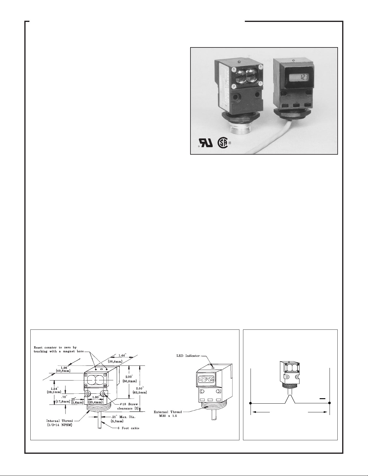
VALU-BEAM 990 Series Sensors
with Built-in Totalizing Counter
VALU-BEAM 990 Series sensors boast the same high optical
performance offered by the front-line 912 Series, and also
contain a built-in 6-digit totalizing counter. Sensor models are
available for opposed, retroreflective, and convergent beam
sensing modes. In addition, there are models for use with both
glass and plastic fiberoptics.
A special infrared retroreflective version is available, which is
designed for counting people passing through entry ways. It has
built-in on/off time delays to minimize the chance of multiple
counts.
The 990 Series VALU-BEAM's 6-digit LCD counter is reset
simply by touching the area of the housing shown with the
permanent magnet supplied with the sensor (see dimension
drawing, below). Standard models automatically reset to zero
upon power-up.
Memory backup option: SMA990 Series sensors with internal memory backup for maintaining "count memory" while power is
removed are available by special order. These models will "hold" a count for over 100 hours, and are indicated by the model number
suffix MB (i.e., "SMA990LVMB" is the memory backup version of sensor model SMA990LV). Contact the factory for availibility
and pricing of these models.
SMA990 Series sensors wire directly to either 10 to 250V ac (50/60Hz) or 12 to 115V dc.
SPECIFICATIONS, SMA990 SERIES VALU-BEAM SENSORS
SUPPLY VOLTAGE: 10 to 250V ac, 50/60Hz or 12 to 115V
dc at less than 20 milliamps.
SENSOR RESPONSE: 15 milliseconds LIGHT, 15 millisec-
onds DARK (except SMA990LT, page 16). 100 millisecond
delay on power up (no counts are entered during this time).
Models with memory backup have no power-up delay. Note:
Some models with memory backup may increment 1 count upon
reapplication of power.
COUNT ENTRY: counts are entered on DARK-to-LIGHT
transition.
COUNT RESET: in standard models, counter is reset to zero
automatically upon applying power to the sensor. All models
may be reset by touching the housing on top of the sensor (see
below) with a permanent magnet (supplied with sensor).
Dimensions, SMA990 Series VALU-BEAMs
CONSTRUCTION: reinforced black VALOX® housing, to-
tally encapsulated circuitry, molded o-ring sealed lenses or fiber
fittings, stainless steel hardware. Meets NEMA standards 1, 2,
3, 3S, 4, 4X, 12, and 13.
CABLE: 6 feet (2m) of PVC-jacketed 2-conductor cable is
standard. Three-pin quick-disconnect ("QD") models are available optionally (one conductor goes unused). Order model
MBCC-312 3-conductor cable for "QD" models (page 18).
INDICATOR LED: top-mounted red LED indicator lights
whenever the sensor "sees" its modulated light source.
OPERATING TEMPERATURE RANGE: 0 to 50 degrees C
(32 to 122 degrees F).
Hookup Diagram
L1
L2
14
+
Brown Blue
10 to 250V ac, 50/60Hz
or 12 to 115V dc
Observe proper polarity for DC hookups.
AC hookups have no polarity.
Page 15

VALU-BEAM 990 Series Sensors
0
0
0
0
Sensing Mode Models
SMA91E &
SMA99R
Voltage: 10 to 250V ac
or 12 to 115V dc;
("E": 10-250V ac/dc)
Range: 200 feet (60m)
Beam: infrared, 880nm;
visible red tracer beam
Effective beam: 0.5" dia.
OPPOSED Mode
SMA91ESR &
SMA99RSR
Voltage: 10 to 250V ac
or 12 to 115V dc;
("ESR": 10-250V ac/dc)
Range: 10 feet (3m)
Beam: infrared, 880nm;
visible red tracer beam
Effective beam: 0.14" dia.
Excess Gain
100
E
X
C
100
E
S
S
G
A
10
I
I
N
1
1 FT 10 FT 100 FT 1000 FT
SMA91E &
SMA99R
DISTANCE
Beam Pattern
60
SMA91E & SMA99R
40
I
20
N
C
0
H
E
20
S
40
60
0
50 100 150 200 250
OPPOSED DISTANCE--FEET
Opposed mode sensors have higher excess gain than other models, and therefore
should be used whenever possible. Opposed mode is the most reliable sensing mode
for counting opaque materials. The small size of these sensors makes them ideal for
many conveyor applications, and their small effective beam size (particularly of the
ESR/RSR models) enables them to reliably count relatively small objects. ESR and
RSR models also have a wide beam angle for very forgiving alignment within the
10-foot range. VALU-BEAM opposed mode sensors have a visible red "tracer
beam" which greatly simplifies sensor alignment.
100
E
X
C
100
E
S
S
G
A
10
I
I
N
1
.1 FT 1 FT 10 FT
SMA91ESR &
SMA99RSR
DISTANCE
100 FT
12
8
I
4
N
C
0
SMA91ESR & SMA99RSR
H
E
4
S
8
12
2 468100
OPPOSED DISTANCE--FEET
RETROREFLECTIVE
SMA990LV
Voltage: 10 to 250V ac
or 12 to 115V dc
Range: 6 inches to
30 feet (9m)
Beam: visible red, 650nm
SMA990LVAG
Voltage: 10 to 250V ac
or 12 to 115V dc
Range: 1 to 15 feet (4,5m)
Beam: visible red, 650nm
(with polarizing filter)
100
E
X
C
E
S
S
G
A
I
I
N
SMA990LV
100
with 3"
with 1"
10
reflector
(BRT-1)
with
1
.1 FT 1 FT 10 FT 100 FT
BRT-T tape
DISTANCE
reflector
(BRT-3)
6
SMA990LV
4
I
2
N
C
0
H
E
2
S
4
6
6 121824300
DISTANCE TO REFLECTOR--FEET
with BRT-3 REFLECTOR
A visible-red light beam reduces the potential for false signals from highly reflective
objects ("proxing") and simplifies alignment. The AG (anti-glare) model polarizes
the emitted light and filters out unwanted reflections, making its use possible in
applications otherwise unsuited to retroreflective sensing (and where reduced
excess gain is acceptable). Maximum range with all units is attained when using the
model BRT-3 3" corner cube retroreflector. See the Banner product catalog for
details about available retroreflective materials.
100
E
X
C
100
E
S
S
G
A
10
I
I
N
1
.1 FT
SMA990LVAG
with one BRT-3
3" retroreflector
1 FT 10 FT 100 FT
DISTANCE
3
SMA990LVAG
2
I
1
N
C
0
H
E
1
S
2
3
36912150
DISTANCE TO REFLECTOR--FEET
with BRT-3 REFLECTOR
15
Page 16

VALU-BEAM 990 Series Sensors
Sensing Mode
RETROREFLECTIVE
Models
SMA990LT
Voltage: 10 to 250V ac
or 12 to 115V dc
Range: 30 feet (9m)
Beam: infrared, 940nm
SMA990CV
Voltage: 10 to 250V ac
or 12 to 115V dc
Focus at 1.5" (38mm)
Beam: visible red, 650nm
Excess Gain
1000
SMA990LT
E
X
C
100
E
with BRT-1 1"
S
reflector
S
G
10
A
I
I
N
1
.1 FT 1 FT 10 FT 100 FT
with
BRT-T
tape
DISTANCE
with BRT-3 3"
reflector
Beam Pattern
6
SMA990LT
4
I
2
N
C
0
H
E
2
S
4
6
6 12 18 24 32
0
DISTANCE TO REFLECTOR--FEET
with BRT-3 reflector
VALU-BEAM model SMA990LT is designed specifically for "people counting".
Its strong (30 foot range) infrared beam is invisible to the eye, and a built-in 1/10
second on/off delay helps prevent multiple counts. Maximum retroreflective signal
strength is attained when using the model BRT-3 corner-cube retroreflector. Other
retroreflective materials may also be used (see Banner product catalog for descriptive information).
1000
SMA990CV
E
X
C
100
E
S
S
G
10
A
I
I
N
1
.1 IN 1 IN 10 IN 100 IN
(Range based on 90%
reflectance white test
card)
DISTANCE
.09
SM990CV
.06
I
.03
N
C
0
H
E
.03
S
.06
.09
1.0 1.5 2.0 2.5
.50
DISTANCE TO 90% WHITE TEST CARD--INCHES
CONVERGENT Mode
FIBER OPTIC Mode
(plastic fiber optics)
OPPOSED
OBJECT
OBJECT
SMA990FP
Voltage: 10 to 250V ac
or 12 to 115V dc
Range: see E.G. curves
Beam: visible red, 650nm
The powerful modulated
visible beam of this sensor
makes it compatible with
all Banner plastic fiber
optic assemblies. Banner
plastic fibers are an economical alternative to glass
fibers when environmental conditions allow (see
below). Banner plastic fiber optics are available in
two core diameters and
with various sensing tip
styles. Standard length is 6
feet. See the Banner product catalog for more fiber
optic information.
VALU-BEAM convergent sensors produce a precise .06" diameter visible red
sensing spot at a focus point 1.5" in front of the sensor lens. Due to its very narrow
depth of field, this model excels at counting small objects only a fraction of an inch
away from backgrounds. This convergent sensor may be used for reliable counting
of some radiused products which flow past at a fixed distance from the sensor lens.
1000
E
X
C
100
E
S
S
G
A
10
I
I
N
PIT26U,
no lens
1
.1 IN 1 IN 10 IN 100 IN
1000
SMA990FP
E
X
C
100
E
S
S
G
A
10
I
I
N
1
.01 IN .1 IN 1 IN 10 IN
PIT46U,
no lenses
with
PBT26U
fiber
SMA990FP
DISTANCE
DISTANCE
Opposed mode,
plastic fibers
PIT46U
with L2
lenses
Diffuse mode,
plastic fibers
(Range based on
90% reflectance
white test card)
with
PBT46U
fiber
1.8
SMA990FP
1.2
I
.6
N
C
0
H
E
.6
S
1.2
1.8
OPPOSED DISTANCE--INCHES
.15
SMA990FP
.10
I
.05
N
C
0
PBT26U PBT46U
H
E
.05
S
.10
.15
DISTANCE TO 90% WHITE TEST CARD--INCHES
12 30
.3 .60
Opposed mode
PIT26U
PIT46U
4
Diffuse mode
1.2 1.5
.9
5
16
DIFFUSE
Environmental Factors for Plastic Fiber Optics
OPERATING TEMPERATURE OF FIBER OPTIC ASSEMBLIES: -30 to +70° C (-20 to +158° F).
CHEMICAL RESISTANCE OF FIBER OPTIC ASSEMBLIES: the acrylic core of the monofilament optical
fiber will be damaged by contact with acids, strong bases (alkalis), and solvents. The polyethylene jacket will
protect the optical fiber from most chemical environments; however, materials may migrate through the jacket
with long-term exposure. Samples of plastic fiber optic material are available from Banner for testing and
evaluation.
Page 17

0
s
s
0
)
VALU-BEAM 990 Series Sensors
FIBER OPTIC Mode
(glass fiber optics)
OPPOSED
OBJECT
RETRO
OBJECT
RETROREFLECTIVE TARGET
DIFFUSE
Models Excess Gain
SMA990F
Voltage: 10 to 250V ac
or 12 to 115V dc
Range: see E.G. curves
Beam: infrared, 880nm
Fiberoptic sensing is often the
answer when, due to space or
environmental limitations, the
sensor itself cannot be placed
at the actual sensing position.
This sensor's powerful modulated infrared beam is compatible with all Banner glass
fiber optics in the opposed,
retroreflective, and diffuse
sensing modes. Glass fiber
optic selection information
may be found in the Banner
catalog. The sensor/fiber interface is waterproof to maintain complete sensing system
moisture rejection.
Opposed mode fiber optic
sensing is often employed in
parts counting applications.
Fiber optics can be built with
sensing ends having windows
that conform to the size and
profile of the part. This allows
most efficient use of the
sensor's emitted light energy.
Refer to the Banner product
catalog for more information.
1000
E
X
100
C
E
S
S
G
10
A
I
I
N
IT13S fibers
1
.1 IN 1 IN 10 IN
100
SMA990F
E
X
100
C
E
S
S
G
10
A
I
I
N
E
X
C
E
S
S
G
A
I
N
with L9 len
and BT13S
fibers
1
.1 FT 1 FT 10 FT 100 FT
100
SMA990F
100
10
I
with
BT13S
fibers
1
.1 IN 1 IN 10 IN 100 IN
SMA990F
Opposed
mode,
glass fibers
IT23S fibers
DISTANCE
Retroreflective
mode, w/BRT-3 3"
target
with L16F len
and BT13S
fibers
DISTANCE
Diffuse mode
(Range based on 90%
reflectance white test card
with
BT23S
fibers
DISTANCE
100 IN
Beam PatternSensing Mode
3
SMA990F
2
I
1
N
C
0
H
E
1
S
2
3
OPPOSED DISTANCE --INCHES
BT13S fiber, retroreflective
6
mode, with BRT-3 reflector
4
I
2
N
C
with L9 lens with L16F lens
0
H
E
2
S
4
6
4 8 12 16 200
DISTANCE TO REFLECTOR--FEET
.1
.075
.050
I
.025
N
C
0
H
E
.025
S
.050
.075
.1
DISTANCE TO 90% WHITE TEST CARD--INCHES
IT13S fibers
4 8 12 16 200
Diffuse mode
.3 .60
IT23S fibers
Opposed mode
SMA990F
BT13S
SMA990F
.9
BT23S
1.2 1.5
Options and Accesories for SMA990 Series Sensors
Memory Backup ("MB") option: SMA990 Series sensors with internal memory backup for maintaining "count memory"
are available by special order. These models, which will "hold" a count for over 100 hours, are indicated by the model suffix "MB"
(example: the memory backup version of model SMA990LV is "SMA990LVMB"). Contact the factory for availability and
pricing on these models.
Quick Disconnect ("QD") option: The VALU-BEAM QD option allows quick and easy removal or replacement of
VALU-BEAM sensors in the field. QD option VALU-BEAM 990 Series sensors have a 3-pin male connector, built into the
sensor's base, which mates with the model MBCC-312 3-conductor female SO-type quick-disconnect cable (one wire goes
unused). To specify the QD option on a sensor, simply add the letters "QD" to the end of the sensor's model number. (Example:
the QD version of the SMA990FMB is "SMA990FMBQD".) Model MBCC-312 SJT-type cable (12' length) must be ordered
separately. See drawings, page 18.
30-foot cable option: Standard VALU-BEAM sensor models (non-QD types, which are normally supplied with a 6-foot long
PVC-covered cable), may optionally be supplied with a 30-foot PVC-covered cable. Thirty feet is the most readily-available
length; lengths longer than 30 feet may also be quoted.
Accessory Mounting Bracket model SMB900: Accessory mounting bracket model SMB900 has curved mounting
slots for versatility in mounting and orientation. The sensor mounts to the bracket by its threaded base, using a jam nut and lockwasher (both included). The bracket accommodates both standard and "QD" sensor models. Bracket material is 11-gauge zincplated steel. The curved mounting slots have clearance for 1/4" screws. See drawings, page 20.
Accessory Mounting Bracket model SMB30SM: This is a swivel mounting bracket. The base of the VALU-BEAM
sensor threads into the bracket's captive swivel ball, which is then held firmly in the desired position when the bracket's two
mounting bolts are tightened.
17
Page 18

VALU-BEAM Modifications and Accessories
Quick-Disconnect ("QD") Cable Option
All Banner VALU-BEAM sensors are available with the "QD"
(Quick-Disconnect) option (below). A 3, 4, or 5-pin connector
Dimensions, "QD" Sensors
Side View, MBCC QD Cable Connector
(depending upon the VALU-BEAM model), built into the sensor's base, mates with the SJT-type
quick disconnect cable described below. Cable must be ordered separately.
The diagrams below show pin configurations for 3, 4, and 5 pin "QD" connectors, which are located
at the base of VALU-BEAM sensors having the "QD" option. Mirror-image pin numbering is used
for the connectors of the mating cables, as shown below. Male contact pins are used in the sensor
connectors. The cable connectors have female receptacles for wiring safety.
Standard VALU-BEAM sensors (non-"QD" models, which are normally supplied with an attached
6-foot long PVC-covered cable) may instead be supplied optionally with an attached 30-foot PVC-
covered cable. Thirty feet is the most readily available length, but lengths longer than 30 feet may
also be quoted.
Pin Configurations for 3-, 4-, and 5-pin "QD" Connectors
Quick Disconnect Cables for VALU-BEAM® Sensors with "QD" Option
(cables must be purchased separately)
QD cable model
and end view
MBCC-312
MBCC-412
MBCC-512
912 Series sensors with
solid-state relay output
All AC sensors:
model prefixes SM2A912,
SM2A91R, SMA912, SMA91R
All emitters:
model prefix SMA91E
All DC sensors:
model prefix SM912
(not used)
915 Series sensors with
e/m relay output
All emitters:
model prefix SMA91E
(not used)
All sensors (except emitters):
model prefixes
SMA915, SMA91R,
SMB915, SMB91R
SMW915, SMW91R
990 Series sensors with
built-in totalizing
counters
All sensors:
model prefixes
SMA990, SMA91E
(not used)
(not used)
18
Page 19

VALU-BEAM Accessories
Armored Jacket
Model AC-6 armored cable jacket for VALUBEAM sensors (not for "QD" models). Six-foot
length. Size: I.D. = 5/16"; O.D. = 7/16".
Extension Cable
Compression Fitting
RF1-2NPS Compression Fitting for attaching
armored cable or PVC tubing to VALU-BEAM
sensors (not for "QD" models).
PVC Cable Tubing
Model PVC-6 flexible PVC tubing for VALUBEAM sensors (not for "QD" models). Six-foot
length. Size: I.D. = 1/4"; O.D. = 3/8".
Extension cable in 100-foot lengths:
Model EC312-100 4-wire cable for SM912 Series dc sensors. Wire colors: brown, blue, black, white.
Model EC312A-100 2-wire cable for emitters and SM2A912 Series 2-wire ac sensors and SMA990
series. Wire colors: brown, blue.
Model EC900A-100 3-wire cable for SMA912 Series ac sensors. Wire colors: brown, blue, black.
Model EC915-100 5-wire cable for SMA915, SMB915, and SMW915 Series ac/dc sensors. Wire
colors: brown, blue, black, white, yellow.
NOTE: extension cable may be ordered in lengths greater than 100 feet on a quote basis.
Upper Covers (lens assemblies)
VALU-BEAM upper covers (above). Upper cover model UC-
900J (on the right in the photo) is a flat, clear Lexan
acts as a dust cover for the lens area when the sensor is mounted
facing up. The UC-900J may be attached to the following VALUBEAMs: E, R, ESR, RSR, LV, and D.
Table I: Replacement Covers
VALU-BEAM
Type:
LVAG
CV, C
DSR, ESR, RSR
F
FP
E, R, LV, D
Uses upper cover
model:
UC-900AG
UC-900C
UC-900DSR
UC-900F
UC-900FP
UC-900L
®
window which
VALU-BEAM "upper covers" consist of a bezel, a lens, and mounting
hardware. Depending upon the model of VALU-BEAM in use, they allow
sensing mode and/or sensing range changes in the field.
Table I below lists the various VALU-BEAM sensor types and the upper cover
models they are supplied with. It tells you which upper cover to order for strictly
replacement purposes. VALU-BEAMs are identified by their model number
suffixes, which designate their sensing mode. For example, an SM912
SM2A912
Table II lists the sensing mode and range changes that may be accomplished by
substituting a different upper cover. For example, if you want to convert an F
(fiberoptic) type VALU-BEAM to a D (diffuse) type, order and install upper cover
model UC-900L. The conversions listed are direct model conversions which may
be made simply by changing VALU-BEAM upper cover assemblies. Other
conversions are possible: contact the Banner applications staff with any questions.
LVAG sensor uses a model UC-900AG upper cover.
LVAG or
Table II: Mode/Range Change Cross-reference
To change:
LV to LVAG
LV to CV
D to DSR
D to F
DSR to F
EF to ESR
RF to RSR
Use
UPPER COVER:
UC-900AG
UC-900C
UC-900DSR
UC-900F
UC-900F
UC-900DSR
UC-900DSR
To change:
LVAG to LV
CV to LV
DSR to D
F to D
F to DSR
Use UPPER
COVER:
UC-900L
UC-900L
UC-900L
UC-900L
UC-900DSR
19
Page 20

VALU-BEAM Accessories
SMB900 Mounting Bracket
SMB30S Mounting Bracket
Accessory mounting bracket
model SMB900 has curved mount-
ing slots for versatility in mounting and orientation. The sensor
mounts to the bracket by its
threaded base, using a jam nut and
lockwasher (both included). The
bracket material is 11-gauge zincplated steel. The curved mounting
slots have clearance for 1/4"
screws.
Swivel mounting bracket model
SMB30S offers the ultimate in flex-
ibility and convenience. The
SMB30S bracket mounts by its
base. The base of the VALUBEAM sensor threads into the captive "ball" of the bracket, which is
locked snugly in position when the
two clamping/mounting bolts are
tightened. Bracket material is black
VALOX®. Hardware is stainless
steel, and bolts are included.
HF1-2NPS Flexible Cable Protector
This black neoprene assembly easily slips over the prewired cable and threads into the base of a VALUBEAM sensor. The flexible extender prevents sharp cable bends and extends the life of cable that is
subject to repeated flexing.
The HF1-2NPS includes a neoprene gland that compresses around the VALU-BEAM cable to provide
an additional seal against moisture.
This flexible conduit protector is resistant to gasoline, alcohol, oil, grease, solvents, and weak acids. It
has a working temperature range of -30° to +100°C (-22 to +212°F). It is UL recognized and CSA
certified.
The HF1-2NPS also threads into the base of OMNI-BEAM, MULTI-BEAM, MAXI-BEAM, and SM30
Series sensors. It is sold in packages of 10 pieces.
WARNING VALU-BEAM photoelectric presence sensors do NOT include the self-checking redundant circuitry necessary
to allow their use in personnel safety applications. A sensor failure or malfunction can result in either an energized or a de-energized
sensor output condition.
!
ANSI machine safety standards for point-of-operation guarding devices. No other Banner sensors or controls are designed to meet these standards, and
they must NOT be used as sensing devices for personnel protection.
Never use these products as sensing devices for personnel protection. Their use as safety devices may create an unsafe condition which
could lead to serious injury or death.
Only MACHINE-GUARD and PERIMETER-GUARD Systems, and other systems so designated, are designed to meet OSHA and
Banner Engineering Corp. 9714 Tenth Ave. No. Minneapolis, MN 55441 Telephone: (612)544-3164 FAX (applications): (612)544-3573
 Loading...