

Page 1
USA Series Protective Mounting Stands
For Selected Light Screen Sensors
Printed in USA P/N 57119
USA Series Description
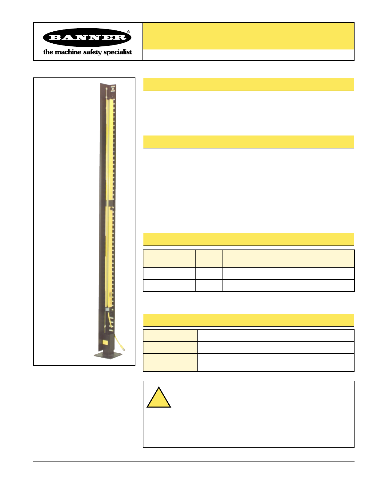
Banner USA Series Protective Mounting Stands are for use with light screen emitters
and receivers. They are designed to deflect physical impact and flying material, such
as weld spatter, preventing damage to the sensor or its lens.
USA Series Features
• Available in two sizes to fit sensors up to 56" long
• Easy to mount to wall, post, machine frame or MSA Series base
• Protects one side and front window of light screen sensor, or combine two in a
U-shaped configuration to protect entire sensor (see Figure 2)
• For use with MICRO-SCREEN
®
, MINI-SCREEN®, or MINI-ARRAY™emitters and
receivers (MINI-SCREEN and MINI-ARRAY applications require the use of MSMB-4
mounting brackets)
USA Series Models
USA Series Specifications
Model Number
Length
“L”
For MICRO-SCREEN
Sensors
For MINI-SCREEN or
MINI-ARRAY Sensors*
USA-PMS-40 40" 4" to 36" 4" to 36"
USA-PMS-62 62" 4" to 56" 4" to 48"
*Requires one MSMB-4 (p/n 48954) mounting bracket pair for each sensor.
Construction 11 ga. AWG cold-rolled steel
Finish Zinc-plated, chromate dip, black
Weight
40": 6.15 lb. (without base)
62": 9.70 lb. (without base)
Shown with
optional MSA-SB-1
Floor-Mounting Base
(sold separately)
WARNING . . .
Maintain Required Separation Distance
The Defined area (light screen) produced by the MICRO-SCREEN®or
MINI-SCREEN®sensors must be placed at a minimum safe distance
from the dangerous motion of the machine being guarded. This
necessary minimum distance is called the separation distance, and is discussed in
Section 3 of MICRO-SCREEN, MINI-SCREEN and MULTI-SCREEN instruction
manuals. Failure to calculate this distance correctly and to maintain minimum
separation distance can result in serious injury or death.
!
Page 2
USA Series Protective Mounting Stands
2
Banner Engineering Corp. • Minneapolis, U.S.A.
Website: http://www.baneng.com • Tel:612.544.3164
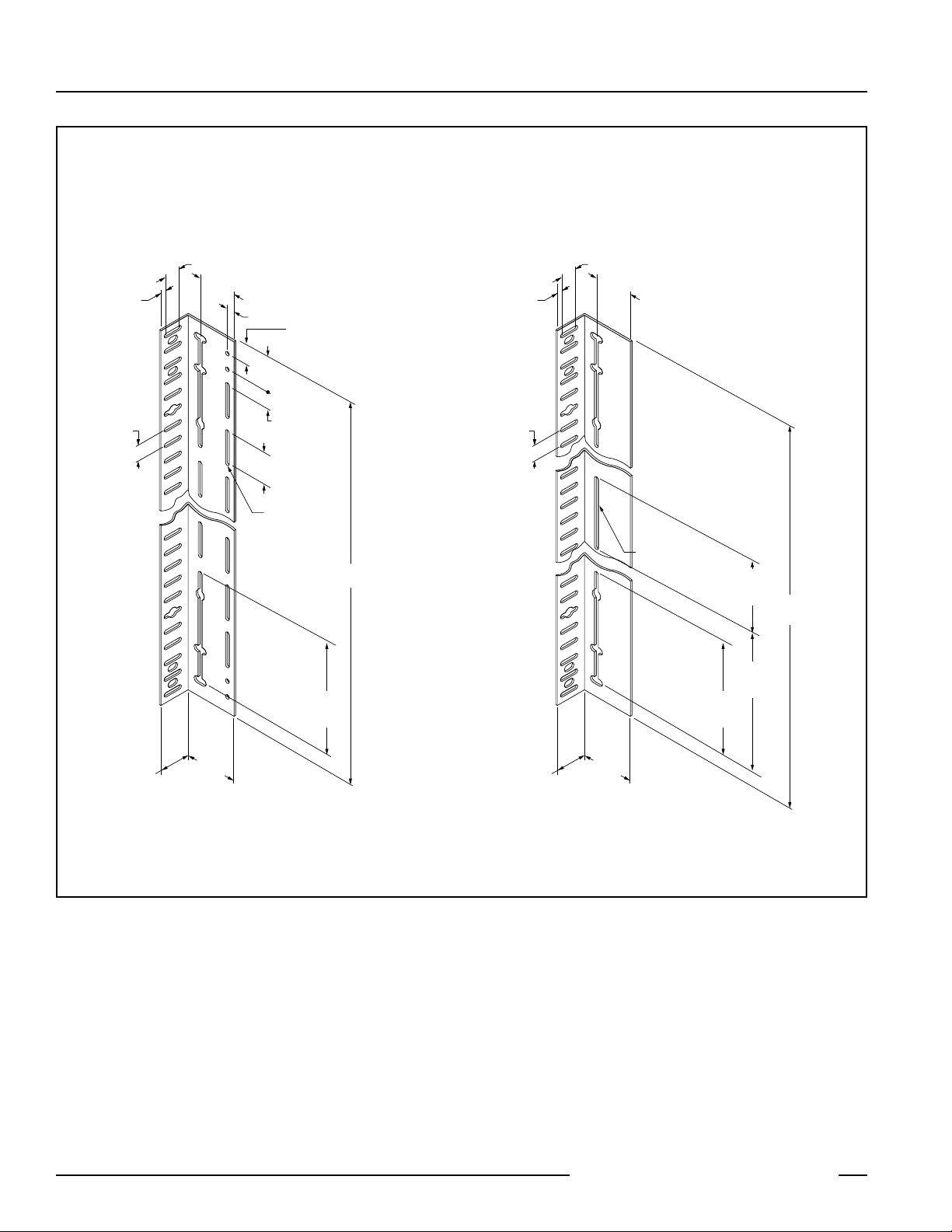
Figure 1. USA Series Protective Stand dimensions
Note: Due to the variety of mounting situations, mounting hardware is not included with these stands.
USA-PMS-40 USA-PMS-62
9.5 mm
(0.38")
25.4 mm Typ.
(1.00")
25.4 mm
(1.00")
63.5 mm
(2.50")
12.7 mm
(0.50")
50.8 mm
(2.00")
25.4 mm
(1.00")
50.8 mm Typ.
(2.00")
7.1 mm Wide Typ.
(0.28")
25.4 mm
(1.00")
174.2 mm
2x
(6.86")
1016 mm
(40.0")
9.5 mm
(0.38")
25.4 mm Typ.
(1.00")
25.4 mm
(1.00")
63.5 mm
(2.50")
7.1 mm Wide Typ.
(0.28")
2x
174.2 mm
(6.86")
2x
203.2 mm
(8.00")
2x
330.2 mm
(13.00")
1651 mm
(62.0")
51 mm
(2.0")
89 mm
(3.5")
51 mm
(2.0")
89 mm
(3.5")
Page 3

USA Series Protective Mounting Stands
3
Banner Engineering Corp. • Minneapolis, U.S.A.
Website: http://www.baneng.com • Tel:612.544.3164
Mounting the USA Series
Banner USA Series Protective Mounting Stands may mount directly to a wall or post,
to the machine frame, or to the accessory base listed below. They may be used
individually, or in pairs, to provide maximum protection. When used in pairs, the two
stands form a U-configuration, with the sensor recessed well back from the front of
the stand.
Figure 2. One Protective Stand protects
back and one side of sensor; or mount two
together to form a U-channel to protect all
sides
Figure 3. Mounts to wall, column, machine
frame or other surface, with sensor against
either of the two sides
Figure 4. Mounts to steel Floor-Mounting
Base (sold separately, hardware included with
base)
Figure 5. Model MSA-SB-1 Floor-Mounting
Base dimensions
USA Series Accessories
Model Number Description
Base
MSA-SB-1
Floor-Mounting Base with hardware
(order one per stand or U-configuration pair of stands)
Brackets
MSMB-4
Brackets for mounting MINI-SCREEN or MINI-ARRAY
(order one per sensor)
This surface
towards the
source of
material
or path of
object
Emitted Light
Path
Emitted Light
Path
Machine Frame,
Building wall/
column,or other
surface*
Emitted Light
Path
*This configuration works only for
MICRO-SCREEN sensors
Machine Frame,
Building wall/
column,or other
surface
Emitted Light
Path
Clearance holes for
M8 or 5/16" bolts for bolting stands
to floor (4) (bolts not supplied)
M10 x 1 mm
for
leveling
bolts
(4 supplied)
127 mm
(5.0")
102 mm
(4.0")
13 mm
13 mm
(0.5")
(0.5")
102 mm
(4.0")
127 mm
(5.0")
Page 4

Banner Engineering Corp., 9714 Tenth Ave. No., Minneapolis, MN 55441 • Phone: 612.544.3164 • Fax: 612.544.3213 • E-mail: sensors@baneng.com
USA Series Protective Mounting Stands
WARRANTY: Banner Engineering Corp. warrants its products to be free from defects for one year. Banner Engineering Corp. will repair or
replace, free of charge, any product of its manufacture found to be defective at the time it is returned to the factory during the warranty
period. This warranty does not cover damage or liability for the improper application of Banner products. This warranty is in lieu of any
other warranty either expressed or implied.
 Loading...