

Page 1
UM-FA-xA Universal Input Safety Modules
For 24V ac/dc operation, solid-state or relay inputs
• Monitors a wide variety of safety and non-safety input devices:
• Optical-based safeguarding devices, such as Safety Laser Scanners
• Positive-opening safety switches used for guard interlocking
• Emergency-stop devices, such as palm buttons and rope/cable pulls
• Standard sensors for non-safety applications, such as photoelectric monitoring position
or end-of-travel.
• The safety inputs can monitor:
• +24V dc solid-state (PNP) outputs in single-channel or dual-channel hookup
• +24V dc source that is switched by hard/relay contacts in single-channel or dual-channel hookup
• Hard/relay contacts in a dual-channel hookup using terminals S11-S12 and S21-S22
• UM-FA-9A: Three normally open (N.O.) output switching channels for connection to control-reliable power interrupt circuits
• UM-FA-11A: Two normally open (N.O.) and one normally closed (N.C.) output switching
channels for connection to control-reliable power interrupt circuits
• Automatic reset or monitored manual reset, depending on hookup
• Design complies with standards ANSI B11.19 Control Reliability, ISO 13850 (EN418), and
ISO 13849-1 (EN954-1) Category 4
• Safety Integrity Level SIL 3 per IEC 61508/IEC 62061
• Category 4 Performance level PL e per ISO 13849-1
• For use in functional stop category 0 applications per ANSI NFPA 79 and IEC/EN 60204-1
• Plug-in terminal blocks
• 24V ac/dc operation
Models Output Switching Channels Safety Output Contact Rating
UM-FA-9A 3 normally open (N.O.) 6A
UM-FA-11A 2 normally open (N.O.), and 1 normally closed (N.C.) 7A
WARNING: Not a Safeguarding Device
This Banner device is considered complementary equipment that is used to augment safeguarding that
limits or eliminates an individual's exposure to a hazard without action by the individual or others. Failure
to properly safeguard hazards per a risk assessment, local regulations and relevant standards
could lead to serious injury or death.
Important... Read This Before Proceeding
The user is responsible for satisfying all local, state, and national laws, rules, codes, and regulations relating to the use of this
product and its application. Banner Engineering Corp. has made every effort to provide complete application, installation, operation, and
maintenance instructions. Please direct any questions regarding the use or installation of this product to the factory applications department at the telephone numbers or address found at http://www.bannerengineering.com.
The user is responsible for making sure that all machine operators, maintenance personnel, electricians, and supervisors are thoroughly familiar with and understand all instructions regarding the installation, maintenance, and use of this product, and with the machinery it
controls. The user and any personnel involved with the installation and use of this product must be thoroughly familiar with all applicable
standards, some of which are listed within the specifications. Banner Engineering Corp. makes no claim regarding a specific recommendation of any organization, the accuracy or effectiveness of any information provided, or the appropriateness of the provided information
for a specific application.
P/N 141249_web
Rev. E
5/28/2013
Page 2

UM-FA-xA Universal Input Safety Modules
Overview
The UM-FA-xA Universal Safety Module (or "Safety Module" or "Module" in this document) is used to increase the safety circuit integrity
(for example, Control Reliability) of a circuit.
As shown in the hookup configurations in Safety Input Device Hookup Options on page 5, the Safety Module is designed to monitor a
1-channel or 2-channel safety switch(es); for example, an E-stop or safety interlock switch, or a 1-channel or 2-channel PNP output from
devices such as a sensor or a safety laser scanner.
Safety Circuit Integrity and ISO 13849-1 Safety Circuit Principles
Safety circuits involve the safety-related functions of a machine that minimize the level of risk of harm. These safety-related functions can
prevent initiation, or they can stop or remove a hazard. The failure of a safety-related function or its associated safety circuit usually
results in an increased risk of harm.
The integrity of a safety circuit depends on several factors, including fault tolerance, risk reduction, reliable and well-tried components,
well-tried safety principles, and other design considerations.
Depending on the level of risk associated with the machine or its operation, an appropriate level of safety circuit integrity (performance)
must be incorporated into its design. Standards that detail safety performance levels include ANSI B11.19 Performance Criteria for Safeguarding and ISO 13849-1 Safety-Related Parts of a Control System.
Safety Circuit Integrity Levels
Safety circuits in International and European standards have been segmented into Categories and Performance Levels, depending on
their ability to maintain their integrity in the event of a failure and the statistical likelihood of that failure. ISO 13849-1 details safety circuit
integrity by describing circuit architecture/structure (Categories) and the required performance (PL) of safety functions under foreseeable
conditions.
In the United States, the typical level of safety circuit integrity has been called "Control Reliability." Control Reliability typically incorporates redundant control and self-checking circuitry and has been loosely equated to ISO 13849-1 Category 3 or 4 and/or Performance
Level “d” or “e” (see ANSI B11.19).
Perform a risk assessment to ensure appropriate application, interfacing/hookup, and risk reduction (see ANSI B11.0 or ISO 12100). The
risk assessment must be performed to determine the appropriate safety circuit integrity in order to ensure that the expected risk reduction
is achieved. This risk assessment must take into account all local regulations and relevant standards, such as U.S. Control Reliability or
European "C" level standards.
Fault Exclusion
An important concept within the requirements of ISO 13849-1 is the probability of the occurrence of a failure, which can be reduced using
a technique termed "fault exclusion." The rationale assumes that the possibility of certain well-defined failure(s) can be reduced via design, installation, or technical improbability to a point where the resulting fault(s) can be, for the most part, disregarded—that is, "excluded" in the evaluation.
Fault exclusion is a tool a designer can use during the development of the safety-related part of the control system and the risk assessment process. Fault exclusion allows the designer to design out the possibility of various failures and justify it through the risk assessment process to meet the requirements of ISO 13849-1/-2.
Monitoring of Safety Devices
Requirements vary widely for the level of safety circuit integrity in safety applications (that is, Control Reliability or Category/Performance
Level) per ISO 13849-1. While Banner Engineering always recommends the highest level of safety in any application, it is the responsibility of the user to safely install, operate and maintain each safety system and comply with all relevant laws and regulations.
Although only three applications are listed (see Input Device Requirements on page 3), the Module can monitor a variety of devices as
long as the input requirements are complied with (see Electrical Installation and Specifications). The Safety Module does not have 500
ms simultaneity between inputs and thus cannot be used for monitoring a two-hand control. In all cases, the safety performance
(integrity) must reduce the risk from identified hazards as determined by the machine's risk assessment.
WARNING: Risk Assesment
The level of safety circuit integrity can be greatly affected by the design and installation of the safety devices and the means of interfacing of those devices. A risk assessment must be performed to determine
the appropriate level of safety circuit integrity to ensure the expected risk reduction is achieved
and all relevant regulations and standards are complied with.
2 www.bannerengineering.com - tel: 763-544-3164 P/N 141249_web
Rev. E
Page 3
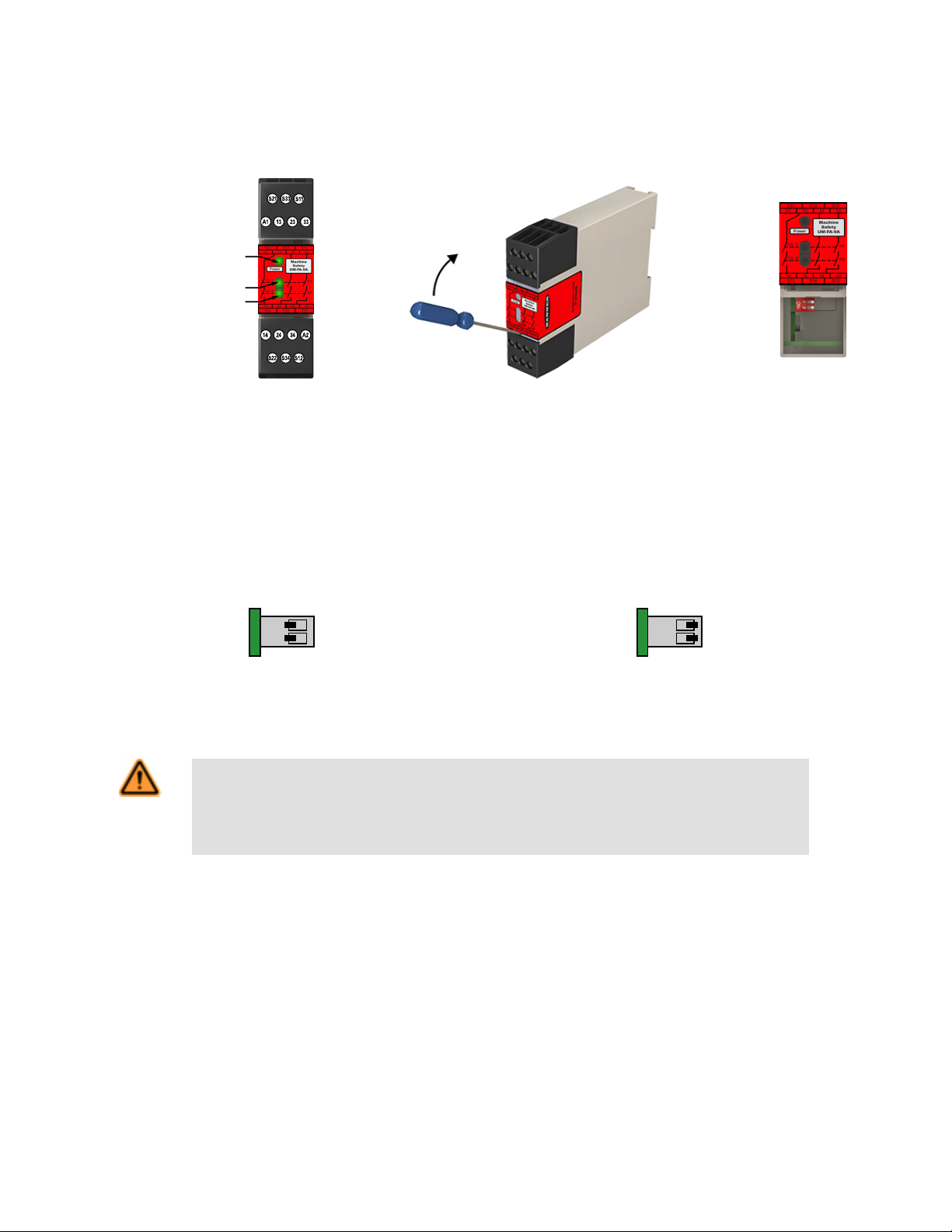
Power ON LED
Channel 1 Active LED
Channel 2 Active LED
1 2
ON
1 2
ON
UM-FA-xA Universal Input Safety Modules
Indicators and Adjustments
The Safety Module has indicators for input power and output relay contact status (K1 and K2); see Figure 1. Features on page 3.
There are no adjustments and no user-serviceable parts.
Figure 1. Features Figure 2. Accessing the DIP Switches
The Safety Module can monitor dry (hard/relay) contacts as well as solid state PNP outputs from sensors or light screens, either in singlechannel or dual-channel mode. To select dry contact inputs and single-channel solid-state inputs, set the two DIP switches under the
lower terminal block to ON (both switches toward the circuit board). To select dual-channel solid-state inputs, set the two DIP switches to
OFF (away from the circuit board). The factory default setting is for dual-channel solid-state input mode (both switches OFF/away from
the circuit board), see Figure 5. on page 7.
Dual- or Single-Channel
Switch 1 and 2: ON
Solid-State Dual-Channel (Default)
Switch 1 and 2: OFF
Figure 3. DIP Switch Settings
Input Device Requirements
WARNING: Incomplete Information
Many installation considerations that are necessary to properly apply input devices are not covered in this
document. Refer to the appropriate device installation instructions to ensure the safe application of
the device.
Optical Sensors
The safety inputs may be used to monitor optical-based devices that use light as a means of detection. These devices include safety light
screens (curtains), safety laser scanners, and multiple/single beam devices (grids/points).
The design and installation of the optical safeguarding device should comply with ANSI B11.19, IEC61496 (all applicable parts), ISO
13855, and/or other applicable standards. Optical safety devices must be placed at an appropriate safety distance (separation distance)
from the safeguarded hazard. Because these devices vary, it is not practical to list specific calculations here. Refer to the applicable
standards and to manufacturer documentation specific to your device for the appropriate calculations and for complete installation information (such as AG4 installation manual p/n 144924).
Interlocked Guards (Gates)
The safety inputs can be interfaced with positive-opening safety switches to monitor the position of an interlock guard or gate. Each
switch must provide electrically isolated contacts: at minimum, one normally closed (N.C.) contact from each individually mounted switch.
The contacts must be of "positive-opening" (direct-opening) design, as described by IEC60947- 5-1, with one or more normally closed
P/N 141249_web
Rev. E
www.bannerengineering.com - tel: 763-544-3164 3
Page 4

UM-FA-xA Universal Input Safety Modules
contacts rated for safety. In addition, the switches must be mounted in a "positive mode," to move/disengage the actuator from its home
position and open the normally closed contact when the guard opens.
The design and installation of the interlocked guard and the safety switches should comply with ANSI B11.19, ISO14119, ISO 14120,
and/or other applicable standards. See the device manufacturer installation instructions for complete information (such as GM-FA-10J p/n
60998, SI-LS83/-LS100 p/n 59622, or SI-HG63 p/n 129465 datasheets).
In higher levels of safety performance, the design of a dual-channel coded magnetic switch typically uses complementary switching, in
which one channel is open and one channel is closed at all times. The inputs of the Safety Module do not support complementary
switching, and thus should not be used with coded magnetic safety switches.
Emergency Stop Push Buttons and Rope/Cable Pull Switches
The safety inputs can be interfaced with positive-opening switches to monitor an emergency-stop (E-stop) push button or rope/cable pull.
The switch must provide one or two contacts for safety which are closed when the switch is armed. Once activated, the E-stop switch
must open all its safety-rated contacts, and must require a deliberate action (such as twisting, pulling, or unlocking) to return to the
closed-contact, armed position. The switch must be a "positive-opening" (or direct-opening) type, as described by IEC 60947-5-1.
Standards ANSI NFPA 79, ANSI B11.19,, IEC/EN60204-1, and ISO 13850 specify additional emergency stop switch device requirements, including the following:
• Emergency-stop push buttons shall be located at each operator control station and at other operating stations where emergency
shutdown is required.
• Stop and emergency-stop push buttons shall be continuously operable and readily accessible from all control and operating stations
where located. Do not mute or bypass E-stop buttons or rope/cable pulls.
• Actuators of emergency-stop devices shall be colored red. The background immediately around the device actuator shall be colored
yellow (where possible). The actuator of a push-button-operated device shall be of the palm or mushroom-head type.
• The emergency-stop actuator shall be a self-latching type.
In addition, for Rope/Cable Pull Installations Only:
• The red wire rope should be easily visible and readily accessible along its entire length. Red markers or flags may be fixed on the
rope to increase its visibility.
• The rope or cable pull must provide constant tension and must have the capability to react to a force in any direction.
• Mounting points, including support points, must be rigid.
• The rope should be free of friction at all supports. Pulleys are recommended.
• The switch must have a self-latching function that requires a manual reset after actuation
Some applications may have additional requirements; comply with all relevant regulations. See the device manufacturer installation instructions for complete information (such as SSA-EB1..-.. p/n 162275, or RP-RM83F.. p/n 141245 data sheets).
WARNING: Emergency Stop Functions
Do not mute or bypass any Emergency Stop device. ANSI B11.19, ANSI NFPA79 and IEC/EN
60204-1 require that the Emergency Stop function remain active at all times.
Mechanical Installation
The Safety Module must be installed inside an enclosure.
It is not designed for exposed wiring. It is the user’s responsibility to house the Safety Module in an enclosure with NEMA 3 (IEC IP54)
rating, or better. The Safety Module mounts directly to standard 35 mm DIN rail.
Heat Dissipation Considerations: For reliable operation, ensure that the operating specifications are not exceeded. The enclosure must
provide adequate heat dissipation, so that the air closely surrounding the Module does not exceed the maximum operating temperature
stated in the Specifications. Methods to reduce heat build-up include venting, forced airflow (for example, exhaust fans), adequate enclosure exterior surface area, and spacing between modules and other sources of heat.
4 www.bannerengineering.com - tel: 763-544-3164 P/N 141249_web
Rev. E
Page 5

UM-FA-xA Universal Input Safety Modules
Electrical Installation
WARNING: Shock Hazard and Hazardous Energy
Always disconnect power from the safety system (for example, device, module, interfacing, etc.)
and the machine being controlled before making any connections or replacing any component.
Electrical installation and wiring must be made by Qualified Person and must comply with the relevant
electrical standards and wiring codes, such as the NEC (National Electrical Code), ANSI NFPA79, or IEC
60204-1, and all applicable local standards and codes.
Lockout/tagout procedures may be required. Refer to OSHA 29CFR1910.147, ANSI Z244-1, ISO
14118, or the appropriate standard for controlling hazardous energy.
Electrical installation must be made by qualified personnel1 and must comply with NEC (National Electrical Code), ANSI/NFPA 79 or
IEC/EN 60204-1, and all applicable local standards. It is not possible to give exact wiring instructions for a device that interfaces to a
multitude of machine control configurations. The following guidelines are general in nature. Perform a risk assessment to ensure appropriate application, interfacing/hookup, and risk reduction (see ANSI B11.0 or ISO 12100).
The Safety Module has no delay function. Its output relay contacts open within 25 milliseconds after a safety input opens. This classifies
the Safety Module as a functional stop "Category 0" control, as defined by ANSI NFPA 79 and IEC/EN 60204-1.
The safety inputs can be connected to:
• +24V dc solid-state (PNP) outputs in single-channel or dual-channel hookup configuration
• +24V dc source that is switched by hard/relay contacts in single-channel or dual-channel hookup configuration
• Hard/relay contacts in a dual-channel hookup configuration using terminals S11-S12 and S21-S22
The UM Safety Module must be configured (via DIP switch) for the appropriate hookup in order to operate properly. When using devices
with redundant solid-state safety outputs (such as the AG4 Safety Laser Scanner OSSDs) or redundant hard contacts switching a +24V
dc source, both the DIP switches must be set to the "OFF" position (default position, see Figure 3. DIP Switch Settings on page 3). This
setting is for solid-state dual-channel hookup using terminals S11-S12 and S21-S22 as described in Figure 5. on page 7.
To configure the Module for dual-channel hookup to monitor a device with redundant hard contacts (such as an emergency-stop button),
set both the DIP switches to the "ON" position. This setting is for dual-channel hookup using terminals S11-S12 and S21-S22 as described in Figure 4. on page 7, or when the dual-channel input is not used (is jumpered) in single-channel hookup configuration as described in Figure 6. on page 8 and Figure 7. on page 8.
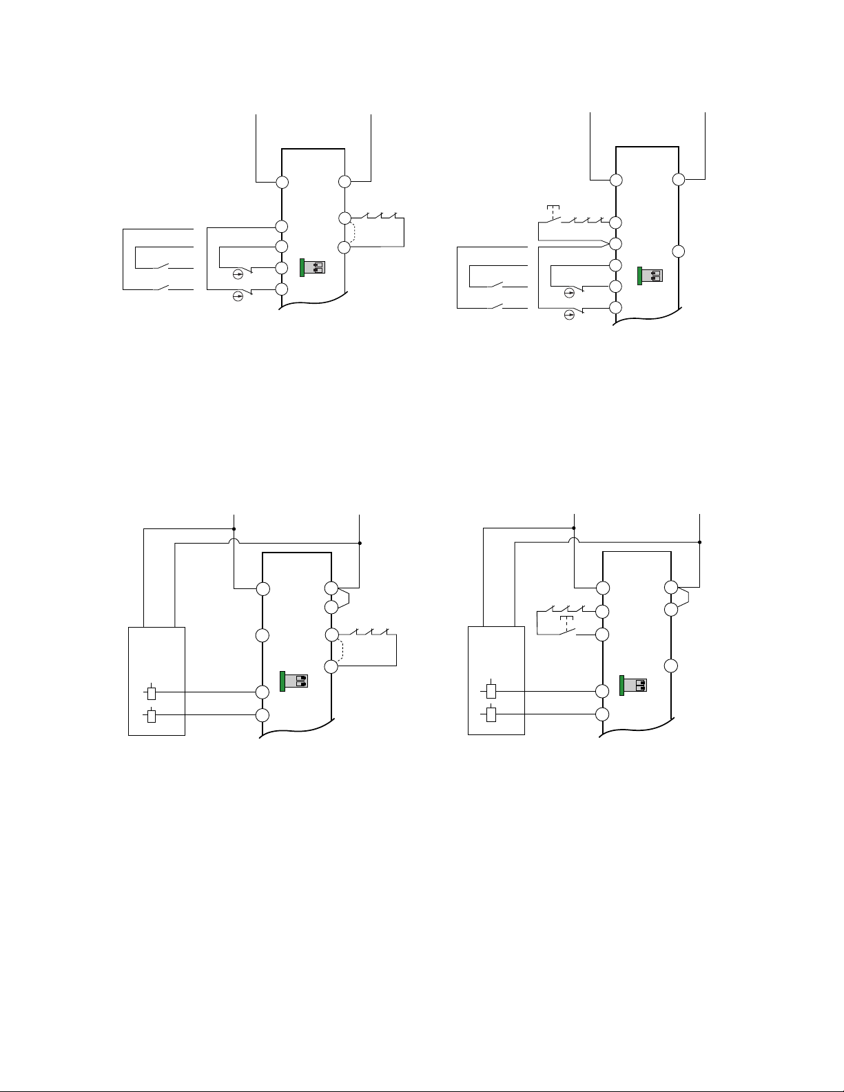
Safety Input Device Hookup Options
The operation of all dual-channel hookup options is concurrent, meaning that input channel 1 and input channel 2 must be in the same
state in both the STOP and RUN condition, but with no simultaneity (timing) requirement between the channels.
The dry (hard/relay) contact dual-channel hookup configuration is able to detect certain failures and faults, such as short circuits, that
could result in a loss of the safety function. Once such a failure or fault is detected, the Safety Module will turn OFF (open) its safety
outputs until the problem is fixed. This circuit can meet ISO 13849-1 Category 2, 3, or 4 requirements, depending on the safety rating and
the installation of the safety input device. This circuit can detect a short circuit between channels or to another source of power, at a
minimum, when the device is actuated.
The solid-state dual-channel hookup configuration cannot detect short circuits between input channels or to secondary sources of
+24V dc. To achieve higher levels of safety performance, the safety device that is connected to input channels 1 and 2 must be capable
of detecting these short circuits and properly responding by turning both channels OFF. This circuit can meet ISO 13849-1 Category 2, 3,
or 4 requirements depending on the safety rating, installation, and the fault detection (for example, short circuit) capabilities of the safety
input device. If short circuit detection is not provided, the circuit can meet only Category 3.
A single device with redundant outputs that can fail in such a manner to lose the safety function, such as a single safety interlocking
switch, can typically meet only a Category 2. See below for means to eliminate or minimize the possibility of failures and faults that could
result in the loss of the safety function(s).
The single-channel hookup configuration cannot detect short circuits to secondary sources of +24V dc or detect the loss of the switching function of the safety input device (that is, it is not redundant) and thus this circuit typically can meet only ISO 13849-1 Category 2.
1
A Qualified Person possesses a recognized degree or certificate or has extensive knowledge, training, and experience to solve problems relating to the emergency stop installation.
P/N 141249_web
Rev. E
www.bannerengineering.com - tel: 763-544-3164 5
Page 6
UM-FA-xA Universal Input Safety Modules
It is recommended that in all circumstances the installation of the Safety Module and its associated safety input devices are installed to
eliminate or minimize the possibility of failures and faults that could result in the loss of the safety function(s). Methods to eliminate or
minimize the possibility of these failures include, but are not limited to:
• Physically separating interconnecting control wires from each other and from secondary sources of power.
• Routing interconnecting control wires in separate conduit, runs, or channels.
• Locating all elements (modules, switches, and devices under control) within one control panel, adjacent to each other, and directly
connected with short wires.
• Properly installing multi-conductor cabling and multiple wires through strain-relief fittings. (Over-tightening of a strain-relief can cause
short circuits at that point.)
• Using positive-opening components as described by IEC 60947-5-1 that are installed and mounted in a positive mode.
• Periodically checking the functional integrity / safety function and training operators, maintenance personnel, and others associated
with the operation of the machine to recognize and immediately correct such failures.
If you have any questions about your intended use, please contact a Banner applications engineer.
WARNING: Wiring of Arc Suppressors
If arc suppressors are used, they MUST be installed as shown across the actuator coil of the stop
control elements (MSCs or MPCEs). NEVER install suppressors directly across the output contacts
of the Safety Device or Module. It is possible for suppressors to fail as a short circuit. If installed directly
across the output contacts, a short-circuited suppressor creates an unsafe condition which may result in serious injury or death.
WARNING: Interfacing MSCs
NEVER wire an intermediate device(s) (for example, PLC, PES, PC) between the Safety Module outputs
and the Master Stop Control Element it switches in such a manner that in the event of a failure there is a
loss of the safety stop command, OR in such a manner that the safety function can be suspended, overridden, or defeated, unless accomplished with the same or greater degree of safety.
Whenever forced-guided, mechanically linked relays are added as intermediate switching devices, a normally closed (N.C.) forced-guided monitor contact from each relay must be added to the series feedback
loop between Safety Module terminals S31 and S32.
WARNING: Multiple Switching Devices
Whenever two or more devices are connected to the same safety module (controller):
• Contacts of the corresponding pole of each switch must be connected together in series. Never
connect the contacts of multiple switches in parallel. Such a parallel connection defeats the switch
contact monitoring ability of the Module and creates an unsafe condition which may result in serious
injury or death.
• Each device must be individually actuated (engaged), then released (or re-armed) and the safe-
ty module reset. This allows the module to check each switch and its wiring to detect faults.
This check must be performed during the prescribed checkouts. Failure to test each device individually
in this manner may result in undetected faults and create an unsafe condition which may result in
serious injury or death.
6 www.bannerengineering.com - tel: 763-544-3164 P/N 141249_web
Rev. E
Page 7
Reset
A2
(No
Connection)
A1
S34
S11
S33
MSC1 MSC2 MSC3
S22
S12
S21
0V
+24V ac/dc
UM-FA-..A
Manual Reset
Devices with
relay output
contacts
Devices with
positive-opening
contacts
DIP Switch
Configuration
See Interfacing MSCs
WARNING
A2
A1
S21
S11
S12
S22
0V
+24V ac/dc
UM-FA-..A
Auto Reset
MSC1 MSC3MSC2
MSC
Monitor
Contacts
or
Jumper
S33
S34
Devices with
relay output
contacts
Devices with
positive-opening
contacts
DIP Switch
Configuration
1 2
ON
1 2
ON
+
+
MSC1 MSC3MSC2
A2
A1
S34
S33
S11
S12
S22
0V dc
0V
+24V dc
+24V dc
+24V dc
+24V dc
UM-FA-..A
Manual Reset
Reset
(No
Connection)
1 2
ON
DIP Switch
Configuration
S21
+
+
A2
A1
S11
S12
S22
0V dc
0V
+24V dc
+24V dc
UM-FA-..A
Auto Reset
MSC1 MSC3MSC2
MSC
Monitor
Contacts
or
Jumper
S33
S34
+24V dc
+24V dc
1 2
ON
DIP Switch
Configuration
S21
UM-FA-xA Universal Input Safety Modules
Dual-Channel Hookup Configuration for Devices with Hard Contacts
Figure 4.
Dual-Channel Hookup Configuration for Solid State Devices (+24V dc Supply Only)
Figure 5.
P/N 141249_web
Rev. E
www.bannerengineering.com - tel: 763-544-3164 7
Page 8

Auto Reset
A2
A1
S21
S11
S12
S22
0V
UM-FA-..A
See Interfacing MSCs
WARNING
MSC1 MSC3MSC2
MSC
Monitor
Contacts
or
Jumper
S33
S34
+24V ac/dc+24V ac/dc
Devices
with relay
output
contacts
Devices
with
positiveopening
contacts
DIP Switch
Configuration
Reset
A2
(No Connection)
A1
S34
S11
S33
MSC1 MSC2 MSC3
S22
S12
S21
0V
+24V ac/dc
UM-FA-..A
Manual Reset
+24V ac/dc
Devices
with relay
output
contacts
Devices
with
positiveopening
contacts
DIP Switch
Configuration
1 2
ON
1 2
ON
Auto Reset
A2
A1
S21
S11
S12
S22
0V dc
UM-FA-..A
DIP Switch
Configuration
MSC1 MSC3MSC2
MSC
Monitor
Contacts
or
Jumper
S33
S34
+24V ac/dc
0V
+
+24V dc
+
A2
A1
S34
S21
S12
S22
0V dc
0V
+24V ac/dc
UM-FA-..A
Manual Reset
(No
Connection)
MSC1 MSC3MSC2
S33
S11
Reset
+24V dc
DIP Switch
Configuration
1 2
ON
1 2
ON
UM-FA-xA Universal Input Safety Modules
Single-Channel Hookup Configuration for Devices with Hard Contacts
Figure 6.
Single-Channel Hookup Configuration for Solid State Devices
8 www.bannerengineering.com - tel: 763-544-3164 P/N 141249_web
Figure 7.
Rev. E
Page 9

*
*
L2
MSC1
MSC2
Machine
Master Stop
Control Elements
*Arc suppressors
(see WARNING)
K1
A
6A max.
6A max.
6A max.
K2
A
K1
B
K2
B
K1
C
K2
C
*
MSC3
13 14
23 24
33 34
L1
Machine
Control
Circuits
Model UM-FA-9A
*
*
L2
MSC1
MSC2
Machine
Master Stop
Control Elements
*Arc suppressors
(see WARNING)
K1
A
6A max.
6A max.
6A max.
K2
A
K1
B
K2
B
K1
C
K2
C
13 14
23 24
31 32
L1
Machine
Control
Circuits
Model UM-FA-11A
Feedback
(optional)
UM-FA-xA Universal Input Safety Modules
Machine Control Circuit Connections
Figure 8.
Connection of Reset Switch
The reset circuit switch can be any mechanical switch, such as a normally open momentary switch, or a two-position key switch. The
reset switch must be capable of reliably switching 12V dc at 10 to 20 milliamps. As shown in the hookup configurations in Safety Input
Device Hookup Options on page 5, the reset switch connects between terminals S11 and S33 of the Safety Module.
The reset switch must be located outside of – and not be accessible from – the area of dangerous motion, and must be positioned so that any area of dangerous motion may be observed by the switch operator during the reset procedure. See warning,
Reset Switch Location.
WARNING: Reset Switch Location
All reset switches must be accessible only from outside, and in full view of, the hazardous area.
Reset switches must also be out of reach from within the safeguarded space, and must be protected against unauthorized or inadvertent operation (for example, through the use of rings or guards). If
any areas are not visible from the reset switch(es), additional means of safeguarding must be provided.
Failure to do so may result in serious bodily injury or death.
Automatic Reset Mode
The Safety Module may be used also with automatic reset. If no MSC-monitor contacts are monitored, a jumper must be installed between terminals S33 and S34 (see the hookup configurations in Safety Input Device Hookup Options on page 5). The Safety Module will
reset and the outputs energize as soon as the inputs return to an ON or "closed-contact" state (after 250 ms OFF state).
The automatic reset mode is useful for some automated processes. However, if automatic reset is used, it is necessary to provide an
alternate means of preventing resumption of hazardous machine motion, until an alternate reset procedure is performed. The alternate
procedure must include a reset/restart switch, located outside the area of dangerous motion, which is positioned so that any area of
dangerous motion may be observed by the switch operator during the reset procedure. See Warning below.
P/N 141249_web
Rev. E
www.bannerengineering.com - tel: 763-544-3164 9
Page 10

UM-FA-xA Universal Input Safety Modules
WARNING: Reset Routine Required
U.S. and international standards require that a reset routine be performed after clearing the cause of a
stop condition (for example, arming an E-stop button, closing an interlocked guard, etc.). Allowing the
machine to restart without actuating the normal start command/device can create an unsafe condition which may result in serious injury or death.
NOTE: The minimum amount of time required for the Module to be in a STOP or OFF condition is 250 milli-
seconds. This “recovery time” (OFF-state) is required for the internal circuitry of the Safety Module to normalize, allowing a reliable reset to occur. A lockout will occur if the Module is cycled too quickly. To clear the
lockout, re-cycle the Module, meeting the minimum OFF time requirements.
Connection to the Machine to be Controlled
The machine hookup diagram shows a generic connection of the Safety Module's redundant output circuits to the master stop control
elements (MSCs). An MSC is defined as an electrically powered device, external to the Safety Module, which stops the machinery being
controlled by immediately removing electrical power to the machine and (when necessary) by applying braking to dangerous motion. This
stopping action is accomplished by removing power to the actuator of either MSC.
External Device Monitoring
To satisfy the requirements of Control Reliability (OSHA and ANSI) Category 3 and 4 of ISO 13849-1 (EN954-1), the master stop control
elements (MSCs) must each offer a normally closed, forced-guided (mechanically linked) monitor contact. Connect one normally closed
monitor contact from each master stop control element in series to S33-S34 in Auto Reset mode and to S11-S33 in Manual Reset mode
(see the hookup configurations in Safety Input Device Hookup Options on page 5).
In operation, if one of the switching contacts of either MSC fails in the energized condition, the associated monitor contact will remain
open. Therefore, it will not be possible to reset the Safety Module. If no MSC-monitor contacts are monitored, a jumper must be installed
as shown the hookup configurations in Safety Input Device Hookup Options on page 5. It is the user's responsibility to ensure that any
single failure will not result in a hazardous condition and will prevent a successive machine cycle.
Overvoltage Category II and III Installations (EN50178 and IEC60664-1)
The Safety Module is rated for Overvoltage Category III when voltages of 1V to 150V ac/dc are applied to the output relay contacts. It is
rated for Overvoltage Category II when voltages of 151V to 250V ac/dc are applied to the output relay contacts and no additional precautions are taken to attenuate possible overvoltage situations in the supply voltage. The Module can be used in an Overvoltage Category III
environment (with voltages of 151V to 250V ac/dc) if care is taken either to reduce the level of electrical disturbances seen by the Module
to Overvoltage Category II levels by installing surge suppressor devices (for example, arc suppressors), or to install extra external insulation in order to isolate both the Safety Module and the user from the higher voltage levels of a Category III environment.
For Overvoltage Category III installations with applied voltages from 151V to 250V ac/dc applied to the output contact(s): the
Safety Module may be used under the conditions of a higher overvoltage category where appropriate overvoltage reduction is provided.
Appropriate methods include:
• An overvoltage protective device
• A transformer with isolated windings
• A distribution system with multiple branch circuits (capable of diverting energy of surges)
• A capacitance capable of absorbing energy of surges
• A resistance or similar damping device capable of dissipating the energy of surges
When switching inductive ac loads, it is good practice to protect the Safety Module outputs by installing appropriately-sized arc suppressors. However, if arc suppressors are used, they must be installed across the load being switched (for example, across the coils of external safety relays), and never across the Safety Module’s output contacts (see WARNING, Arc Suppressors).
10 www.bannerengineering.com - tel: 763-544-3164 P/N 141249_web
Rev. E
Page 11

UM-FA-xA Universal Input Safety Modules
Checkout Procedures
CAUTION: Disconnect Power Prior to Checkout
Before performing the initial checkout procedure, make certain all power is disconnected from the
machine to be controlled.
Dangerous voltages may be present along the Safety Module wiring barriers whenever power to the machine control elements is ON. Exercise extreme caution whenever machine control power is or may
be present. Always disconnect power to the machine control elements before opening the enclosure housing of the Safety Module.
At installation or replacement and at machine set up, a Designated Person2 must test each input device connected to the safety module
for proper machine shutdown response. A Designated Person must check for proper operation, physical damage, mounting (looseness),
and excessive environmental contamination. This must also take place on a periodic schedule determined by the user, based on the
severity of the operating environment and the frequency of switching. Adjust, clean, repair, or replace components as needed when any
parts or assemblies are damaged, broken, deformed, or badly worn; or if the electrical/mechanical specifications (for the environment and
operating conditions) have been exceeded. Always test the control system for proper functioning under machine control conditions
after performing maintenance, replacing the safety module, or replacing any component(s) of the safety circuit.
Initial Checkout
1. Remove power from the machine control elements.
2. Ensure the safety device is in a STOP or "open-contact" state (for example, actuate the E-stop switch to open its contacts).
3. Apply power to the Safety Module at terminals A1 and A2 (see the hookup configurations in Safety Input Device Hookup Options on
page 5). Verify that only the Input Power indicator is ON (Figure 1. Features on page 3). If either input channel 1 (K1) or input channel
2 (K2) indicators are ON at this point, disconnect the input power and check all wiring. Return to step 2 after the cause of the problem
has been corrected.
4. Reset or otherwise cause the safety device to reach an ON or "closed-contact" state (for example, arm the E-stop switch to close its
contacts).
5. Reset the safety module.
Automatic: Ch1 (K1) and Ch2 (K2) indicators should come ON, and the safety output contacts should close as soon as the input
device(s) are ON.
Manual: From an open condition, close the reset switch for approximately ¼ second, and then re-open. The Ch1 (K1) and Ch2
(K2) indicators should both come ON steady at this time. If either indicator comes ON before the reset switch is
opened, disconnect the input power and check all wiring. Return to step 2 after correcting the problem.
6. Cause the safety device to generate a STOP or "open-contact" state (for example, actuate the E-stop switch to open its contacts).The
Ch1 (K1) and Ch2 (K2) indicators should turn OFF simultaneously. If either indicator remains ON, disconnect the input power and
check all wiring. Return to step 2 after the cause of the problem has been corrected.
7. If more than one safety device is series-connected to the Safety Module, run the above checkout procedure individually for EACH
device.
8. Close and secure the enclosure in which the Safety Module is mounted. Apply power to the machine control elements and perform
the Periodic Checkout Procedure.
WARNING: Multiple Safety Devices
When two or more safety devices are used, each device must be individually actuated, causing a
STOP or open-contact condition, then reset/rearmed and the Safety Module reset (if using manual
reset mode). This allows the monitoring circuits to check each device and its wiring to detect faults. Failure to test each device individually in this manner may result in undetected faults and create an
unsafe condition which may result in serious injury or death.
2
A Designated Person is identified in writing by the employer as being appropriately trained to perform a specified checkout procedure.
P/N 141249_web
Rev. E
www.bannerengineering.com - tel: 763-544-3164 11
Page 12

UM-FA-xA Universal Input Safety Modules
Periodic Checkout
The functioning of the Safety Module and the device(s) connected to it must be verified on a regular periodic basis to ensure proper
operation (see also the machine manufacturer’s recommendations).
1. With the machine running, cause the safety device to generate a STOP or "open-contact" state (for example, actuate the E-stop
switch to open its contacts). Verify that the machine stops as expected.
2. Reset or otherwise cause the safety device to reach an ON or "closed-contact" state. Verify that the machine does not restart.
3. If using manual reset mode, close the reset switch for approximately ¼ second and then open it. Verify that the machine can be
restarted by normal initiation.
4. If more than one safety device is series-connected to the Safety Module, run the above checkout procedure individually for EACH
device.
Repairs
Do not attempt any repairs to this Banner device; it contains no field-replaceable components. Contact the Banner Application
Engineers, who will attempt to troubleshoot the system from your description of the problem. If they conclude that a component is defective, they will issue an RMA (Return Merchandise Authorization) number for your paperwork, and give you the shipping address to return
the device to Banner for warranty repair or replacement as needed.
Important: Pack the Banner device carefully. Damage that occurs in return shipping is not covered by warranty.
CAUTION: Abuse of Module After Failure
If an internal fault has occurred and the Module will not reset, do not tap, strike, or otherwise attempt to
correct the fault by a physical impact to the housing. An internal relay may have failed in such a man-
ner that its replacement is required.
If the Module is not immediately replaced or repaired, multiple simultaneous failures may accumulate such that the safety function can not be guaranteed.
Specifications
Supply Voltage and Current
24V dc ± 10% (SELV-rated supply according to EN
IEC 60950, NEC Class 2)
24V ac ± 10%, 50/60Hz (NEC Class 2-rated transformer)
Power Consumption
Approx. 2W/2VA
Supply Protection Circuitry
Protected against reverse polarity and transient voltages
Overvoltage Category
Output relay contact voltage 1V to 150V ac/dc: Cat-
egory III
Output relay contact voltage 151V to 250V ac/dc:
Category II (Category III, if appropriate overvoltage reduction is provided, as described.)
Pollution Degree
2
Output Response Time
25 milliseconds typical
Input Requirements: Safety Input Switch
2-Channel (contacts) hookup: 10 to 20 mA steady
state at 12V dc
NOTE: Inputs are designed with a brief contact-clean-
ing current of 100 mA when initially closed.
Solid-State Dual Channel hookup: 5 to 20 mA steady
state at 18 to 28V dc sourcing ( PNP), < 2 mA leakage
current
Single-Channel hookup: 40 to 100 mA at 24V ac/dc ±
10%; 50/60 Hz
Input Requirements: Reset Switch
20 mA at 12V dc, hard contact only
Minimum OFF-State Recovery Time
250 ms (When used with the AG4 Safety Laser Scanner, the “Restart delay time after PF release” must be
configured for 280 ms or greater.)
12 www.bannerengineering.com - tel: 763-544-3164 P/N 141249_web
Rev. E
Page 13

UM-FA-xA Universal Input Safety Modules
Low Current Rating
The 5 μm gold-plated contacts allow the switching of
low current/low voltage. In these low-power applications, multiple contacts can also be switched in series
(for example, “dry switching”). To preserve the gold
plating on the contacts, do not exceed the following
max. values at any time:
Min. voltage: 1V ac/dc
Max. voltage: 60V
Min. current: 5 mA ac/dc
Max. current: 300 mA
Min. power: 5 mW (5 mVA)
Max. power: 7 W (7 VA)
High Current Rating
If higher loads must be switched through one or more
of the contacts, the minimum and maximum values of
the contact(s) changes to:
Min. voltage: 15V ac/dc
Max. voltage: 250V ac/dc
Min. current: 30 mA ac/dc
Max. current: 6 A for UM-FA-9A; 7 A for UM-FA-11A
Min. power: 0.45 W (0.45 VA)
Max. power: 200 W (1,500 VA) for UM-FA-9Z; 200 W
(1,750 VA) for UM-FA-11A
Output Configuration
Model UM-FA-9A: 3 normally open (N.O.) output
channels
Model UM-FA-11A: 2 normally open (N.O.) output
channels and 1 normally closed (N.C.) auxiliary output
channel
Each normally open output channel is a series connection of contacts from two forced-guided (mechanically
linked) relays, K1-K2.The normally closed Aux. output
channel of the UM-FA-11A is a parallel connection of
contacts from two forced-guided relays, K1-K2.
Contacts
AgNi, 5 μm gold-plated
Mechanical life
> 20,000,000 operations
Electrical life (switching cycles of the output contacts,
resistive load)
150,000 cycles at 1,500 VA; 1,000,000 cycles at 450
VA; 2,000,000 cycles at 250 VA; 5,000,000 cycles at
125 VA
NOTE: Transient suppression is recommended when
switching inductive loads. Install suppressors across
load. Never install suppressors across output contacts
(see Warning, Arc Suppressors).
Indicators
3 green LED indicators: Power ON, K1 energized, K2
energized
Construction
Polycarbonate housing. Rated NEMA 1, IEC IP40; Terminals IP20
Mounting
Mounts to standard 35 mm DIN rail track. Safety Module must be installed inside an enclosure rated NEMA
3 (IEC IP54), or better.
Vibration Resistance
10 to 55 Hz at 0.35 mm displacement per IEC
60068-2-6
Operating Conditions
Temperature: 0 °C to +50 °C (+32 °F +122 °F)
Humidity: 90% at +50 °C maximum relative humidity
(non-condensing)
Category / Performance Level (EN ISO13849-1)
Cat. 4 / PL e (Figure 4. on page 7 or Figure 5. on page
7 with solid-state devices with short-circuit detection or
with fault exclusions on external 2-channel wiring)
Cat. 3 / PL c (Figure 5. on page 7 with dry (hard/relay)
contact switching +24V dc or Solid-State devices without short-circuit detection)
Cat. 2 / PL c (Figure 6. on page 8 and Figure 7. on
page 8)
MTTFd
HIGH
DC
HIGH
SIL / SIL CL (IEC61508 and EN62061)
SIL 3 (Figure 4. on page 7 or Figure 5. on page 7 with
Solid-State devices with short-circuit detection or with
fault exclusions on external 2-channel wiring)
SIL 2 (Figure 5. on page 7 with Solid-State devices
without short-circuit detection, Figure 6. on page 8 and
Figure 7. on page 8)
PFHd
5.1 × 10
-10
Proof Test Interval
20 years
Certifications
P/N 141249_web
Rev. E
www.bannerengineering.com - tel: 763-544-3164 13
Page 14

UM-FA-xA Universal Input Safety Modules
Dimensions
Certifications and Standards
EC Declaration of Conformity (DOC)
Banner Engineering Corp. herewith declares that the UM-FA-9A and UM-FA-11A Universal Safety Modules for industrial control are
in conformity with the provisions of the Machinery Directive (98/37/EEC) and all essential health and safety requirements have been met.
For more information, visit http://www.bannerengineering.com/.
Standards and Regulations
The list of standards below is included as a convenience for users of this Banner device. Inclusion of the standards below does not imply
that the device complies specifically with any standard, other than those specified in the Specifications section of this manual.
U.S. Application Standards
ANSI B11.0 Safety of Machinery, General Requirements, and Risk Assessment
ANSI B11.19 Performance Criteria for Safeguarding
ANSI NFPA 79 Electrical Standard for Industrial Machinery
International/European Standards
ISO 12100 Safety of Machinery – General Principles for Design — Risk Assessment and Risk Reduction
IEC 60204-1 Electrical Equipment of Machines Part 1: General Requirements
ISO 14119 (EN 1088) Interlocking Devices Associated with Guards – Principles for Design and Selection
ISO 14120 Safety of machinery – Guards – General requirements for the design and construction of fixed and movable guards
ISO 13857 Safety Distances . . . Upper and Lower Limbs
ISO 13850 (EN 418) Emergency Stop Devices, Functional Aspects – Principles for Design
ISO 13855 (EN 999) The Positioning of Protective Equipment in Respect to Approach Speeds of Parts of the Human Body
IEC 61508 Functional Safety of Electrical/Electronic/Programmable Electronic Safety-Related Systems
IEC 62061 Functional Safety of Safety-Related Electrical, Electronic and Programmable Control Systems
ISO 13849-1 (EN 954-1) Safety-Related Parts of Control Systems
IEC 60947-1 Low Voltage Switchgear – General Rules
IEC 60947-5-1 Low Voltage Switchgear – Electromechanical Control Circuit Devices
IEC 60947-5-5 Low Voltage Switchgear – Electrical Emergency Stop Device with Mechanical Latching Function
IEC 60529 Degrees of Protection Provided by Enclosures
14 www.bannerengineering.com - tel: 763-544-3164 P/N 141249_web
Rev. E
Page 15

UM-FA-xA Universal Input Safety Modules
Banner Engineering Corp Limited Warranty
Banner Engineering Corp. warrants its products to be free from defects in material and workmanship for one year following the date of
shipment. Banner Engineering Corp. will repair or replace, free of charge, any product of its manufacture which, at the time it is returned
to the factory, is found to have been defective during the warranty period. This warranty does not cover damage or liability for misuse,
abuse, or the improper application or installation of the Banner product.
THIS LIMITED WARRANTY IS EXCLUSIVE AND IN LIEU OF ALL OTHER WARRANTIES WHETHER EXPRESS OR IMPLIED (INCLUDING, WITHOUT LIMITATION, ANY WARRANTY OF MERCHANTABILITY OR FITNESS FOR A PARTICULAR PURPOSE), AND
WHETHER ARISING UNDER COURSE OF PERFORMANCE, COURSE OF DEALING OR TRADE USAGE.
This Warranty is exclusive and limited to repair or, at the discretion of Banner Engineering Corp., replacement. IN NO EVENT SHALL
BANNER ENGINEERING CORP. BE LIABLE TO BUYER OR ANY OTHER PERSON OR ENTITY FOR ANY EXTRA COSTS, EXPENSES, LOSSES, LOSS OF PROFITS, OR ANY INCIDENTAL, CONSEQUENTIAL OR SPECIAL DAMAGES RESULTING FROM ANY
PRODUCT DEFECT OR FROM THE USE OR INABILITY TO USE THE PRODUCT, WHETHER ARISING IN CONTRACT OR WARRANTY, STATUTE, TORT, STRICT LIABILITY, NEGLIGENCE, OR OTHERWISE.
Banner Engineering Corp. reserves the right to change, modify or improve the design of the product without assuming any obligations or
liabilities relating to any product previously manufactured by Banner Engineering Corp.
 Loading...