

Page 1

s
ULTRA-BEAM Ultrasonic Proximity Sensors
925 Series with switched (electromechanical relay) output
Models: SUA925QD 105 to 130V ac, 50/60Hz SUB925QD 210 to 260V ac, 50/60Hz
Response Pattern
NOTES:
1) Response pattern is drawn for the maximum
range setting of the ULTRA-BEAM.
2) Response pattern is drawn for a 2 square foot
solid surface.
3) Symmetry of the pattern may be assumed in all
sensing planes.
4) The rounded portion of the curve past the 20
foot point indicates an area where sensing is
unreliable. Effective range is from 20 inches to
20 feet (0,5 to 6 meters).
6
B
E
A
M
W
I
I
D
T
H
925 Series ULTRA-BEAM
4
2
F
E
0
SENSING AXIS
E
T
2
4
6
5 101520250
DISTANCE TO 2FT X 2FT TARGET--FEET
The Banner 925 Series ULTRA-BEAM is an economical ultrasonic sensor with relay output and a sensing range of 20 inches to
20 feet (0,5 to 6 meters). ULTRA-BEAM 925 Series sensors are
ideal for long-range proximity requirements which fall beyond the
limits of photoelectric response, and are the solution for many
applications which require reflective sensing of non-reflective
materials. Popular applications include bin-level sensing/control
and presence sensing of transparent materials.
Sensing range is easily adjusted using the top-mounted 15-turn
clutched range control. When the range is set, objects passing
through the sensor's area of response will be reliably sensed from
the set range down to 16 inches from the face of the ULTRABEAM. The minimum range setting is 20 inches (0,5m). Objects
which pass beyond the set range will be ignored. The ULTRABEAM has an easily-visible top mounted red LED indicator which
lights whenever an object is detected.
For reliable detection, objects to be sensed must present at least one
square foot (0,1 square meter) of surface area for each 10 feet of
sensor-to-object distance. The response curve (above) illustrates
the sensing pattern which results for a 2 square foot target approaching from either side. The pattern is drawn for the maximum
range setting of the ULTRA-BEAM. Symmetry of this pattern
may be assumed in all sensing planes.
The ULTRA-BEAM is ruggedly constructed with epoxy-encapsulated circuitry and housed in a tough, corrosion-proof VALOX
enclosure. The ultrasonic transducer is protected by a stamped
metal screen. The transducer will not be damaged by temporary
contact with moisture, but must be kept free of heavy contamination for efficient operation. The output is an SPDT form "C" relay
for easy interfacing to most loads (see specifications). An integral
5-pin connector is standard. A mating industrial duty 12 foot cable,
model MBCC-512, is sold separately.
Specifications, 925 Series Ultrasonic Sensors with Electromechanical Relay Output
SUPPLY VOLTAGE: model SUA925QD 105 to 130V ac, 50/
60Hz; model SUB925QD 210 to 260V ac, 50/60Hz. 6VA.
SENSING RANGE: 20 inches to 20 feet (0,5 to 6 meters).
Minimum required target area is 1 square foot (0,1 square meter)
for each 10 feet (3 meters) of sensing range.
SENSING HYSTERESIS: 5% of range setting.
RANGE ADJUSTMENT: 15-turn clutched potentiometer with
slotted brass element, located under o-ring gasketed access screw
on top of sensor. Use small, flat-blade screwdriver to adjust.
INDICATOR LED: red LED indicator on top of sensor lights
when object is sensed (when output relay is energized).
RESPONSE TIME: 100 milliseconds ON and OFF.
OUTPUT: one form "C" SPDT relay, silver-nickel alloy contacts.
Capacity: 150 watts or 600VA maximum power (resistive load).
Maximum voltage: 250V ac or 30V dc (resistive load).
Maximum current: 5 amps (resistive load).
Minimum load: 5V dc @ 100 milliamps.
Mechanical life: 10,000,000 operations.
NOTE: install suitable value metal oxide varistor (MOV)
across contact(s) used to switch an inductive load.
OUTPUT CONNECTOR: integral threaded 5-pin quick-disconnect. 12foot mating cable, model MBCC-512, is sold separately (see page 2).
CONSTRUCTION: Epoxy-encapsulated circuitry.
Rugged, glass-filled VALOX
®
housing. NEMA 1, 3, and 12.
OPERATING TEMPERATURE: 0 to 50°C (32 to 122°F).
®
WARNING These ultrasonic presence sensors do NOT include the self-checking redundant circuitry necessary to allow their use in
personnel safety applications. A sensor failure or malfunction can result in either an energized or a de-energized sensor output condition.
!
Only MACHINE-GUARD and PERIMETER-GUARD Systems, and other systems so designated, are designed to meet OSHA and ANSI machine safety
standards for point-of-operation guarding devices. No other Banner sensors or controls are designed to meet these standards, and they must NOT be
used as sensing devices for personnel protection.
Printed in USA P/N 03420D4B
Never use these products as sensing devices for personnel protection. Their use as safety devices may create an unsafe condition which
could lead to serious injury or death.
Page 2
UL TRA-BEAM 925 Series Sensors
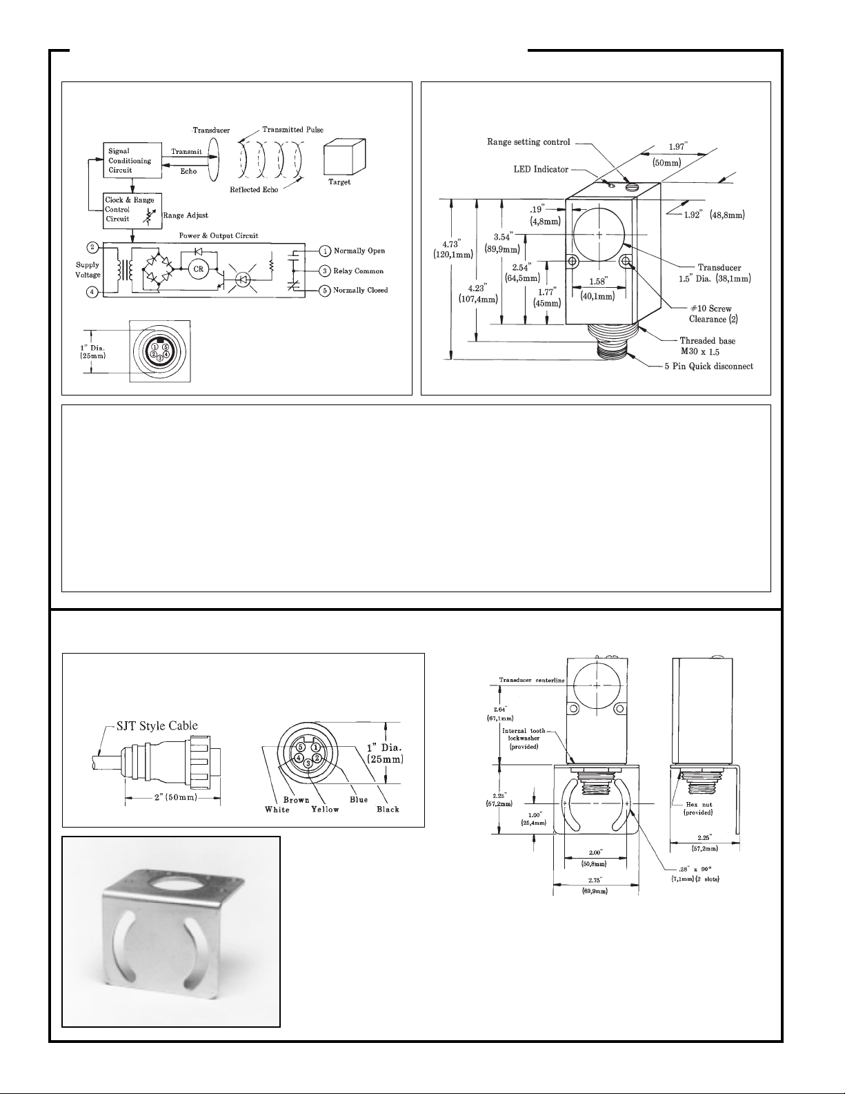
Functional Schematic and Hookup Information,
Dimensions, 925 Series Sensors
925 Series
ULTRA-BEAM 925 Series sensors have a
male 5-pin quick-disconnect ("QD") connector (left) built into the sensor's base.
This connector mates with the MBCC-512
minifast™ style quick-disconnect cable (12
feet long, order separately, see below).
Setup Procedure , 925 Series ULTRA-BEAM Sensors
Proper operation of an ULTRA-BEAM 925 Series sensor requires that
it be mounted securely, on a firm surface, at least 24 inches away from
side walls. At least 48 inches is required between adjacent ULTRABEAMs with parallel sensing beams. Greater separation is required if
the sensing beams cross. Less than 48 inches of separation is allowable
if the adjacent sensing beams point away from each other.
With the ULTRA-BEAM mounted in place, set the object to be
detected at the desired distance, with the surface to be detected directly
in front of the sensor and perpendicular to the beam.
Turn the RANGE potentiometer to the fully counterclockwise position,
then turn the control clockwise until the sensor's red LED indicator
comes on. Verify this range setting by moving the object away from the
sensor (LED should go out), then back towards the sensor (LED should
come on again at about the same distance as before). It is best to set the
range with the object at the maximum distance at which you expect to
detect that object.
Minimum target size required for proper operation of the ULTRABEAM 925 Series sensor is about 1 square foot for each 10 feet of sensorto-object distance.
Accessories for 925 Series ULTRA-BEAM Sensors
MBCC-512 minifast™ "QD" Cable (12 feet long)
Connector Side View
SMB900 Mounting Bracket
Cable End View (female pins)
SMB900 Mounting Bracket
Accessory mounting bracket
model SMB900 (photo at left
and drawing, above right) has
curved mounting slots for versatility in mounting and orientation. The sensor mounts to the bracket by its threaded
base, using a jam nut and lockwasher (both included). The bracket material is 11-gauge
zinc-plated steel. The curved mounting slots have clearance for 1/4" screws.
An internal tooth lockwasher and hex mounting nut are supplied with the sensor.
Banner Engineering Corp. 9714 Tenth Ave. No. Minneapolis, MN 55441 Telephone: (612) 544-3164 FAX (applications): (612) 544-3573
 Loading...