

Page 1
ULTRASONIC
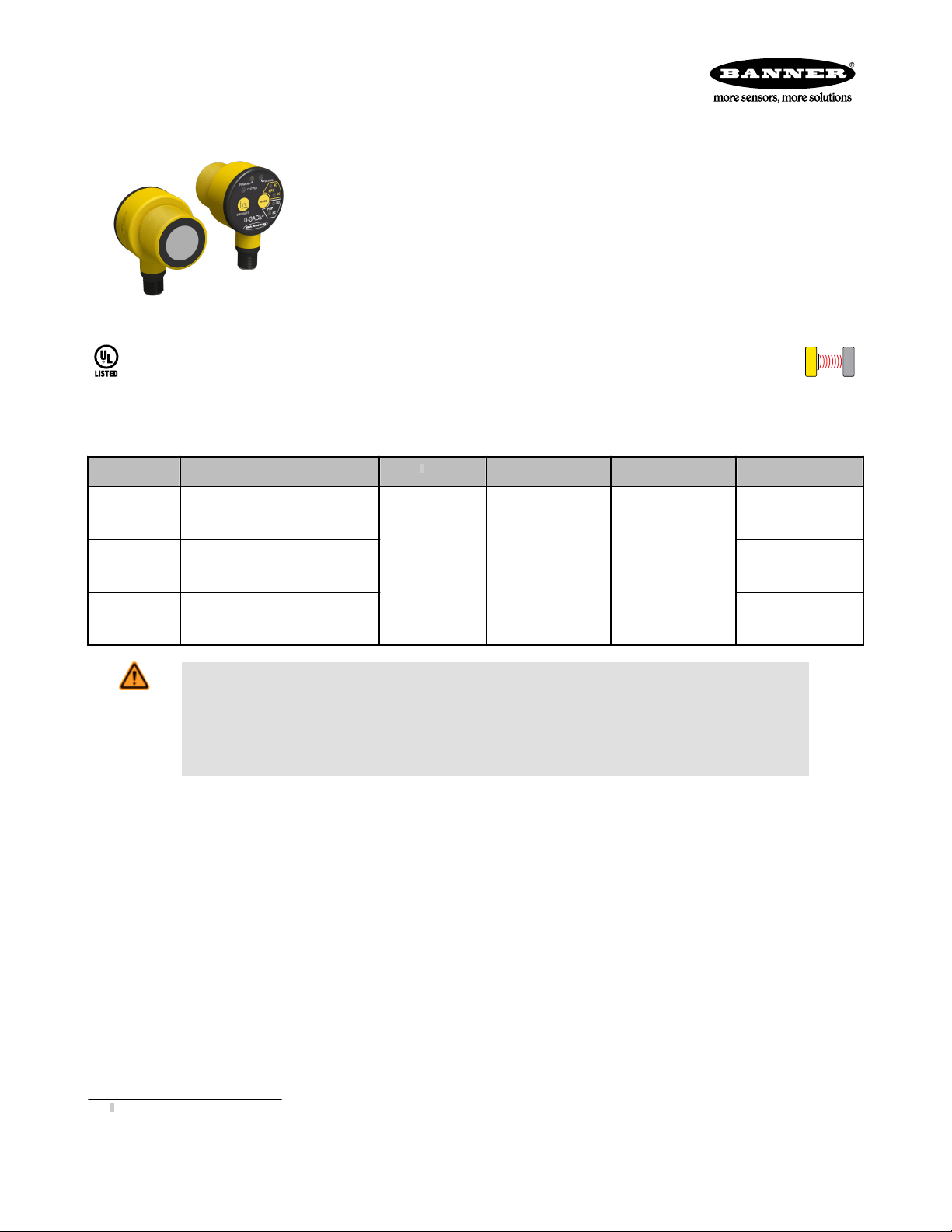
U-GAGE® T30UX Series with Discrete Output
Ultrasonic Sensor with TEACH-Mode Configuration
• 1, 2 and 3 m (3.28, 6.56, and 9.84 ft) versions with short dead zones (10% of
max range)
• Built-in temperature compensation
• Fast, easy-to-use TEACH-Mode programming; no potentiometer adjustments
• Remote TEACH for security and convenience
• Wide operating temperature range of −40° to +70° C (−40° to +158° F)
• Outputs can be set for either NPN (sinking) or PNP (sourcing), Normally Open
(N.O.) or Normally Closed (N.C.)
• Compact, self-contained, right-angle sensor package with fully encapsulated
electronics
Models
Models Range and Frequency Cable
T30UXDA
T30UXDB
T30UXDC
100 mm to 1 m (3.9 in to 39 in)
224 kHz
200 mm to 2 m (7.8 in to 78 in)
174 kHz
300 mm to 3 m (11.8 in to 118 in)
114 kHz
Standard 2 m
(6.5 ft) cable
WARNING: Not To Be Used for Personnel Protection
Never use this device as a sensing device for personnel protection. Doing so could lead to serious
injury or death. This device does not include the self-checking redundant circuitry necessary to allow its
use in personnel safety applications. A sensor failure or malfunction can cause either an energized or deenergized sensor output condition.
1
Supply Voltage Discrete Output Response Time
45 ms
10 to 30V dc
NPN, PNP, NO,
NC, Selectable
92 ms
135 ms
1
Only standard 2 m (6.5 ft) cable models are listed. For 4-Pin Euro-Style integral QD, add suffix “Q8” to the model number (for example, T30UXDAQ8). For 150 mm (6 in) PUR pigtail
cable with 4-Pin threaded Euro-Style QD, add suffix “QPMA” to the model number (for example, T30UXDAQPMA). For 9 m (30 ft) cable, add suffix “W/30” to the model number (for
example, T30UXDA W/30). A model with a QD connector requires a mating cable; see Quick-Disconnect Cables on page 11.
P/N 138381_web
Rev. G
8/19/2013
Page 2
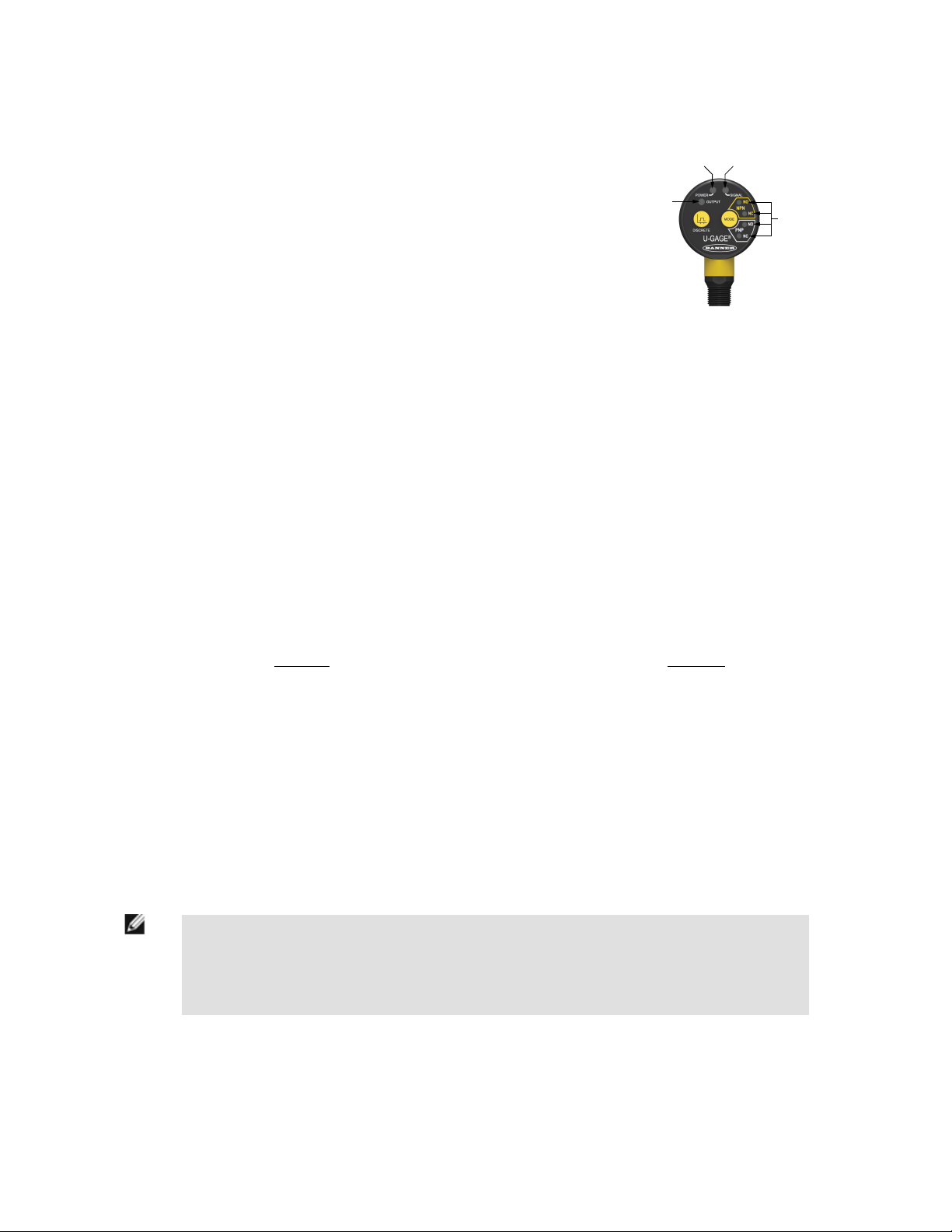
Power ON/OFF
LED (Green)
Discrete Output
LED (Amber)
Signal Strength
LED (Red)
Mode LEDs
(Amber)
C
m/s
= 20 √
273 + T
C
ft/s
=
49 √460 + T
F
C
U-GAGE® T30UX Series with Discrete Output
Overview
The U-GAGE® T30UX is an easy-to-use ultrasonic sensor with extended range and
built-in temperature compensation. Simple push button configuration provides flexibility for a variety of applications.
Easy-to-see indicator LEDs communicate the status of the sensor. The Green “Power” LED ON indicates that the sensor is in Run Mode (the sensor’s normal operating
condition). The Red “Signal” LED indicates the target signal strength. The Amber
“Output” LED indicates that the output is enabled and the sensor is receiving a signal
within the window limits (depending on NO or NC). The Amber “Mode” LED indicates
the currently selected mode.
Figure 1. Features
Principles of Operation
Ultrasonic sensors emit one or multiple pulses of ultrasonic energy, which travel through the air at the speed of sound. A portion of this
energy reflects off the target and travels back to the sensor. The sensor measures the total time required for the energy to reach the
target and return to the sensor. The distance to the object is then calculated using the following formula: D = ct ÷ 2
D = distance from the sensor to the target
c = speed of sound in air
t = transit time for the ultrasonic pulse
To improve accuracy, an ultrasonic sensor may average the results of several pulses before outputting a new value.
Temperature Effects
The speed of sound is dependent upon the composition, pressure and temperature of the gas in which it is traveling. For most ultrasonic
applications, the composition and pressure of the gas are relatively fixed, while the temperature may fluctuate.
In air, the speed of sound varies with temperature according to the following approximation:
In metric units:
C
= speed of sound in meters per second C
m/s
In English units:
= speed of sound in feet per second
ft/s
TC = temperature in °C TF = temperature in °F
Temperature Compensation
Changes in air temperature affect the speed of sound, which in turn affects the total time for the echo measured by the sensor. An
increase in air temperature shifts both sensing window limits closer to the sensor. Conversely, a decrease in air temperature shifts both
limits farther away from the sensor. This shift is approximately 3.5% of the limit distance for a 20° C change in temperature.
The T30UX series ultrasonic sensors are temperature compensated. This reduces the error due to temperature by about 90%. The sensor will maintain its window limits to within 2.2% over the -40° to +70° C (−40° to +158° F) operating range of the sensor.
NOTE:
• Exposure to direct sunlight can affect the sensor’s ability to accurately compensate for changes in temperature.
• If the sensor is measuring across a temperature gradient, the compensation will be less effective.
Sensor Configuration
Two TEACH methods may be used to configure the sensor:
• Teach individual minimum and maximum limits, or
Rev. G
• Use Auto-Window feature to center a sensing window around the taught position.
2 www.bannerengineering.com - tel: 763-544-3164 P/N 138381_web
Page 3
T T
T
U-GAGE® T30UX Series with Discrete Output
The sensor may be configured either via its push button, or via a remote switch. Remote configuration also may be used to disable the
push button, preventing unauthorized personnel from adjusting the configuration settings. To access this feature, connect the white wire
of the sensor to 0V dc, with a remote configuration switch between the sensor and the voltage.
Configuration is accomplished by following the sequence of input pulses. The duration of each pulse (corresponding to a push button
“click”), and the period between multiple pulses, are as “T”: 0.04 seconds < T < 0.8 seconds
Remote line configuration requires a greater than 1 second pause between pulse sequences.
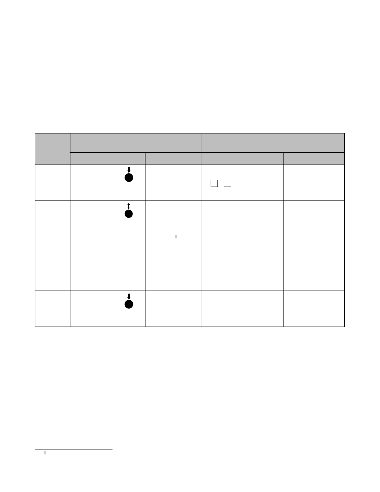
Mode Setup - Output Configuration
Sensors can be set up for either NPN (sinking) or PNP (sourcing). In addition, the user can select between Normally Open (N.O.) and
Normally Closed (N.C.) operation. Normally Open is defined as the output energizing when the target is present. Normally Closed is
defined as the output energizing when the target is absent (see Figure 2. Teaching independent minimum and maximum limits on page
4).
Output Configuration
Mode
Select Output
Save and
Activate
Mode
0.04 sec. < “click” < 0.8 sec.
Procedure Result Procedure Result
Push and hold
MODE push button
for > 2 seconds
“Click” the MODE
push button to cycle
to correct selection:
• NPN - Normally
Open
• NPN - Normally
Closed
• PNP - Normally
Open
• PNP - Normally
Closed
Push and hold
MODE push button
for > 2 seconds
Push Button
Power LED: OFF
Mode LED: Flashing
Amber shows previously selected mode
Power LED: OFF
Mode LED: Flashes to
indicate currently selected mode (120 second time out2)
Power LED: ON
Green
Mode LED: ON Amber
for selected mode
Remote Line
0.04 sec. < T < 0.8 sec.
Double-pulse the remote line
• Single-pulse for NPN - Normally Open
• Double-pulse for NPN - Normally Closed
• Triple-pulse for PNP - Normally Open
• Quad-pulse for PNP - Normally Closed
No action required; sensor will return to Run Mode
Power LED: OFF
Mode LED: Flashing
Amber shows previously
selected mode
Power LED: ON Green
Mode LED: ON to indi-
cate currently selected
mode (Sensor returns to
RUN mode)
None
Teaching Minimum and Maximum Limits
General Notes on Teaching
• The sensor will return to RUN mode if the first TEACH condition is not registered within 120 seconds after the initial 2 second hold on
the Discrete push button.
• To exit TEACH mode without saving any changes, press and hold the Discrete push button or remote line longer than 2 seconds
(before teaching the second limit). The sensor will revert to the last saved limits.
• After the first limit is taught, the sensor will remain in TEACH mode until the TEACH sequence is finished or exited by a 2 second hold
on the Discrete push button or remote line.
2
The sensor will revert to previously saved configuration and return to RUN mode if TEACH is inactive for 120 seconds after the initial 2 second hold on push button
P/N 138381_web
Rev. G
www.bannerengineering.com - tel: 763-544-3164 3
Page 4
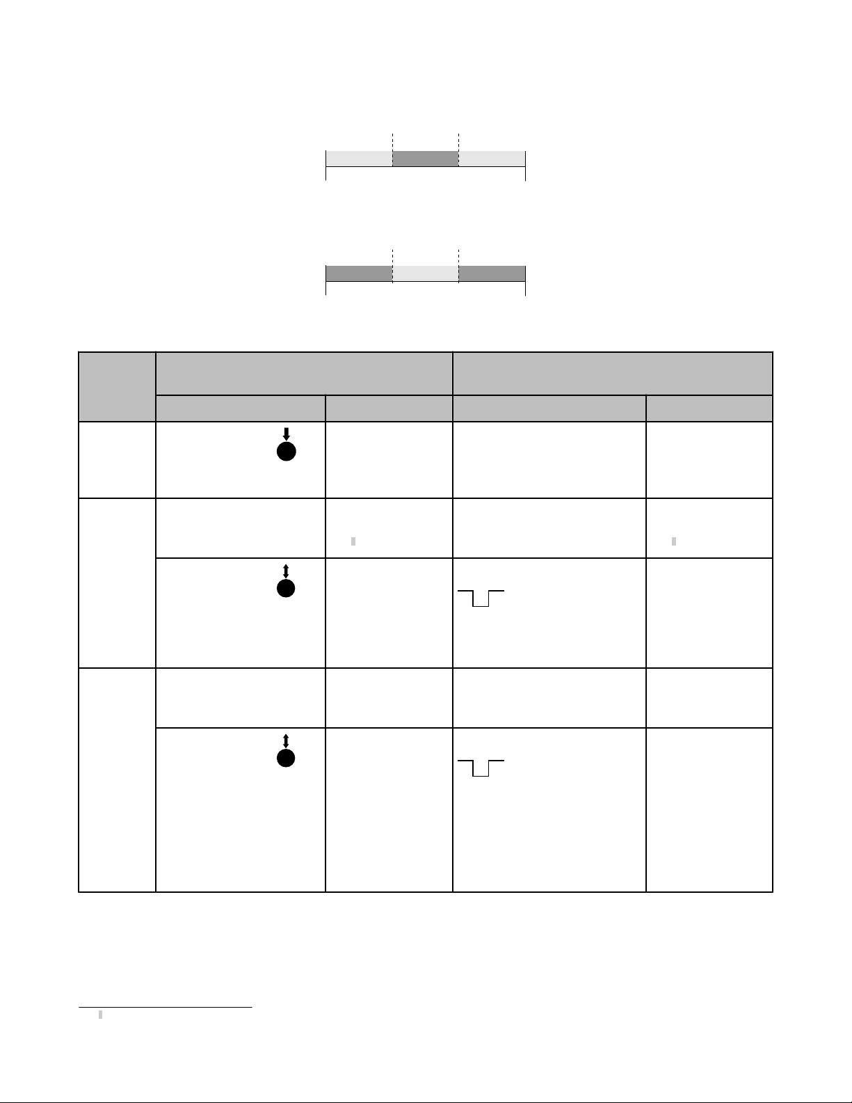
Output OFF Output ON Output OFF
Minimum
Limit
Maximum
Limit
Output ON Output ONOutput OFF
Minimum
Limit
Maximum
Limit
Normally Closed Operation
Normally Open Operation
T
T
U-GAGE® T30UX Series with Discrete Output
Figure 2. Teaching independent minimum and maximum limits
TEACH
Mode
Teach First
Limit
Teach Second Limit
Push Button
0.04 sec. < “click” < 0.8 sec.
Procedure Result Procedure Result
Push and hold the
Discrete push button
longer than 2 seconds
Position the target for the first
limit (120 second time out)
“Click” the Discrete
push button
Position the target for the second limit (no time out)
“Click” the Discrete
push button
Power LED: OFF
Output LED: ON
Signal LED: Must be
ON Red or Flashing
Red3
Teach Accepted
Power LED: OFF
Output LED: Flashing
Teach Not Accepted
Output LED: ON
Signal LED: Must be
ON Red or Flashing
Red
Teach Accepted
Output LED: ON or
OFF, depending on
NO or NC Mode
Power LED: ON
Teach Not Accepted
Output LED: Flashing
Power LED: OFF
Remote Line
0.04 sec. < T < 0.8 sec.
No action required; sensor is ready
None
for first limit teach
Position the target for the first limit Signal LED: Must be
ON Red or Flashing
3
Red
Single-pulse the remote line
Teach Accepted
Power LED: OFF
Output LED: Flashing
Teach Not Accepted
Power LED: ON
Position the target for the second
limit (no time out)
Signal LED: Must be
ON Red or Flashing
Red
Single-pulse the remote line
Teach Accepted
Output LED: ON or
OFF, depending on
NO or NC Mode
Power LED: ON
Teach Not Accepted
Output LED: Flashing
Power LED: OFF
3
Sensor will not Teach or indicate “Teach Not Accepted” when there is no signal present (Signal LED Red or Flashing Red)
4 www.bannerengineering.com - tel: 763-544-3164 P/N 138381_web
Rev. G
Page 5

Output OFF Output ON Output OFF
Position
PositionPosition
Taught Position
Output ON Output ON
Output OFF
Taught Position
Normally Closed Operation
Normally Open Operation
Position
T
T
U-GAGE® T30UX Series with Discrete Output
Teaching Limits Using the Auto-Window Feature
Teaching the same limit twice automatically centers a window on the taught position (see Figure 4. Window Size on page 5 for window
sizes).
General Notes on Teaching
• The sensor will return to RUN mode if the TEACH condition is not registered within 120 seconds after the initial 2 second hold on the
Discrete push button.
• To exit TEACH mode without saving any changes, press and hold the Discrete push button or remote line longer than 2 seconds
(before teaching the second limit). The sensor will revert to the last saved limits.
• After the first limit is taught, the sensor will remain in TEACH mode until the TEACH sequence is finished or exited by a 2 second hold
on the Discrete push button or remote line.
Models Window
"A" suffix ± 10 mm (0.4 in)
"B" suffix ± 20 mm (0.8 in)
"C" suffix ± 30 mm (1.2 in)
Figure 4. Window Size
Figure 3. Using the Auto-Window feature for teaching each
Push and hold the
TEACH
Mode
Discrete push button
longer than 2 seconds
Position the target for the center of window (120 second time
out)
Teach First
Limit
“Click” the Discrete
push button
Re-Teach
Limit
Without moving the
target, “click” the Discrete push button
again
output
Push Button
0.04 sec. < “click” < 0.8 sec.
Remote Line
0.04 sec. < T < 0.8 sec.
Procedure Result Procedure Result
Power LED: OFF
Output LED: ON
Signal LED: Must be
ON Red or Flashing
Red4
Teach Accepted
Power LED: OFF
Output LED: Flashing
Teach Not Accepted
Output LED: ON
Teach Accepted
Output LED: ON or
OFF, depending on
NO or NC Mode
No action required; sensor is ready
for first limit teach
Position the target for the center of
window
Single-pulse the remote line
Without moving the target, singlepulse the remote line again
None
Signal LED: Must be
ON Red or Flashing
4
Red
Teach Accepted
Power LED: OFF
Output LED: Flashing
Teach Not Accepted
Output LED: ON
Teach Accepted
Output LED: ON or
OFF, depending on NO
or NC Mode
4
Sensor will not Teach or indicate “Teach Not Accepted” when there is no signal present (Signal LED Red or Flashing Red)
P/N 138381_web
Rev. G
www.bannerengineering.com - tel: 763-544-3164 5
Page 6

Output OFF Output ON
Taught Position
(background surface)
Near
Range
Sensor
Output
ON
Sensor
Output
OFF
Any object in this area will switch
the output, whether or not the object
returns a good signal to the sensor.
Sensing Distance
T
U-GAGE® T30UX Series with Discrete Output
Push Button
0.04 sec. < “click” < 0.8 sec.
Remote Line
0.04 sec. < T < 0.8 sec.
Procedure Result Procedure Result
Power LED: ON
Teach Not Accepted
Output LED: Flashing
Power LED: OFF
Power LED: ON
Teach Not Accepted
Output LED: Flashing
Power LED: OFF
Figure 5. An application for the Auto-Window feature (retroreflective mode)
Remote Line TEACH
General Notes
• Run Mode is the sensor’s normal operating condition
• The duration of each Pulse is defined as “T”: 0.04 < T < 0.8 s
• A Hold will exit TEACH MODE and return to Run Mode with previously saved changes. The duration of a Hold is: T > 2 s
• A Timeout will occur if a condition is not registered within 120 seconds, causing the sensor to return to Run Mode (during sensor
configuration only)
• Sensor configuration user feedback shown on Green LED. See flowchart.
• The Red Signal LED will be ON whenever the target is in view.
6 www.bannerengineering.com - tel: 763-544-3164 P/N 138381_web
Rev. G
Page 7

TEACH MODE
(1st pulse teaches 1st limit)
Teach 2nd limit
Output Configuration Menu
NPN/NO
NPN/NC
PNO/NO (default)
PNP/NC
Advanced Sensor
Configuration Menu
Push button
enabled ( default)
Push button
disabled
Temp. c omp
enabled ( default)
Temp. c omp
disabled
Toggle push button enable /disable
(legacy method )
Restore fact ory defaults
Run Mode
1x
2x
3x
4x
8x
1x
1x
3x
2x
4x
1x
2x
3x
4x
Power LED OFF ,
Output LED Flas hing
Power LED OFF .
Mode LED Flashing
Power LED OFF ,
Mode LEDs OFF
Flash Power :
1x f or enabled, Repeat tw ice
2x f or disabled, Repeat tw ice
All LEDs off for 1 s
Power LED ON
Output LED ON or OFF
NPN/NO LED ON
NPN/NC LED ON
PNP/NO LED ON
,
PNP/NC LED ON
Flash Power 1x,
Repeat twic e
Flash Power 2x,
Repeat twic e
Flash Power 3x,
Repeat twic e
Flash Power 4x,
Repeat twic e
Power LED ON,
All other LEDs in normal
operating condition
Exit
No valid target
No valid target
120 second Timeout
120 second Timeout
2 s Hold
2 s Hold
2 s Hold
(depending on NO or NC)
U-GAGE® T30UX Series with Discrete Output
P/N 138381_web
Rev. G
www.bannerengineering.com - tel: 763-544-3164 7
Page 8

U-GAGE® T30UX Series with Discrete Output
Specifications
Sensing Range
“A” suffix models: 100 mm to 1 m (3.9 in to 39 in)
“B” suffix models: 200 mm to 2 m (7.8 in to 78 in)
“C” suffix models: 300 mm to 3 m (11.8 in to 118 in)
Ultrasonic Frequency
“A” suffix models: 224 kHz
“B” suffix models: 174 kHz
“C” suffix models: 114 kHz
Supply Voltage
10 to 30V dc (10% max. ripple) at 40 mA, exclusive of
load
Supply Protection Circuitry
Protected against reverse polarity and transient voltages
Output Configuration
Discrete (switched) output models: SPST solid-state
switch. Configurable as NPN (sinking) or PNP (sourcing) via Mode push button. Normally Open (NO) or
Normally Closed (NC) operation is also selectable via
Mode push button (see Mode Setup - Output Configu-
ration on page 3).
The default setting is PNP/NO
Output Rating
Discrete output models: 100 mA max.
OFF-state leakage current: NPN: < 200 μA at 30V dc
(see NOTE 1); PNP: < 10 μA at 30V dc
ON-state saturation voltage: NPN: < 1.6V at 100 mA;
PNP: < 3V at 100 mA
Output Protection Circuitry
Protected against short circuit conditions
Output Response Time
“A” suffix models: 45 ms
“B” suffix models: 92 ms
“C” suffix models: 135 ms
Delay at Power-up
500 ms
Temperature Effect
0.02% of distance/°C
Repeatability
“A” suffix models: 0.1% of distance (0.5 mm min.)
“B” suffix models: 0.1% of distance (1.0 mm min.)
“C” suffix models: 0.1% of distance (1.5 mm min.)
Sensing Hysteresis
“A” suffix models: 2 mm
“B” suffix models: 3 mm
“C” suffix models: 4 mm
Minimum Window Size
10 mm (0.4 in)
Adjustments
Sensing window limits: TEACH-Mode of near and far
window limits may be set using the push button or remotely via TEACH input.
Output Configuration: NPN, PNP, Normally Open
(NO), Normally Closed (NC) select (see Mode Setup -
Output Configuration on page 3 or Remote Line
TEACH on page 6).
Advanced configuration options: Push button enabled/disabled, temperature compensation enabled/
disabled (see Remote Line TEACH on page 6)
Indicators
See Figure 1. Features on page 2
Construction
Housing: PBT polyester
Push buttons: polyester
Transducer: epoxy /ceramic composite
Environmental Rating
Leakproof design, ratedIP67 (NEMA 6)
Connections
2 m (6.5 ft) or 9 m (30 ft) shielded 4-conductor (with
drain) PVC cable, 150 mm (6 in) PUR Euro-style pigtail
(QPMA), or 4-pin integral Euro-style connector (Q8)
Operating Conditions
Temperature: −40 °C to +70 °C (−40 °F to +158 °F)
Humidity: 95% at +50 °C (non-condensing)
Vibration and Mechanical Shock
All models meet Mil. Std. 202F requirements method
201A (vibration: 10 to 60 Hz max., double amplitude
0.06 in, max acceleration 10G). Also meets IEC
947-5-2; 30G 11 ms duration, half sine wave
Application Note
The temperature warmup drift upon power-up is less
than 1% of the sensing distance.
Certifications
CE Pending
NOTE 1: NPN < 200 μA for load impedance > 3 kΩ; for load current of 100 mA, leakage < 1% of load
current
8 www.bannerengineering.com - tel: 763-544-3164 P/N 138381_web
Rev. G
Page 9

200 mm
150 mm
100 mm
50 mm
0
0 200 mm
(8.0")
400 mm
(16.0")
600 mm
(24.0")
800 mm
(32.0")
1000 mm
(40.0")
Width
Distance
50 mm
100 mm
150 mm
200 mm
8.0"
6.0"
4.0"
2.0"
0
2.0"
4.0"
6.0"
8.0"
100 x 100 mm
400 mm
300 mm
200 mm
100 mm
0
0 400 mm
(16.0")
800 mm
(32.0")
1200 mm
(48.0")
1600 mm
(64.0"
2000 mm
(80.0")
Width
Distance
100 mm
200 mm
300 mm
400 mm
16.0"
12.0"
8.0"
4.0"
0
4.0"
8.0"
12.0"
16.0"
100 x 100 mm
400 mm
300 mm
200 mm
100 mm
0
0 600 mm
(24.0")
1200 mm
(48.0")
1800 mm
(72.0")
2400 mm
(96.0")
3000 mm
(120.0")
Width
Distance
100 mm
200 mm
300 mm
400 mm
16.0"
12.0"
8.0"
4.0"
0
4.0"
8.0"
12.0"
16.0"
100 x 100 mm
200 mm
150 mm
100 mm
50 mm
0
0 200 mm
(8.0")
400 mm
(16.0")
600 mm
(24.0")
800 mm
(32.0")
1000 mm
(40.0")
Width
Distance
50 mm
100 mm
150 mm
200 mm
8.0"
6.0"
4.0"
2.0"
0
2.0"
4.0"
6.0"
8.0"
25 mm Rod
10 mm Rod
400 mm
300 mm
200 mm
100 mm
0
0 400 mm
(16.0")
800 mm
(32.0")
1200 mm
(48.0")
1600 mm
(64.0")
2000 mm
(80.0")
Width
Distance
100 mm
200 mm
300 mm
400 mm
16.0"
12.0"
8.0"
4.0"
0
4.0"
8.0"
12.0"
16.0"
25 mm Rod
10 mm Rod
400 mm
300 mm
200 mm
100 mm
0
0 600 mm
(24.0")
1200 mm
(48.0")
1800 mm
(72.0")
2400 mm
(96.0")
3000 mm
(120.0")
Width
Distance
100 mm
200 mm
300 mm
400 mm
16.0"
12.0"
8.0"
4.0"
0
4.0"
8.0"
12.0"
16.0"
25 mm Rod
10 mm Rod
20
30
10
0
0 500 mm
(20.0")
1000 mm
(40.0")
1500 mm
(60.0")
2000 mm
(80.0")
2500 mm
(100.0")
3000 mm
(120.0")
Target Rotation
(Degrees)
Distance
10
20
30
1 meter Target Rotation
2 meter Target Rotation
3 meter Target Rotation
U-GAGE
® T30UX Series with Discrete Output
Performance Curves
With Plate Target (Typical)
1-Meter Models 2-Meter Models 3-Meter Models
With Rod Target (Typical)
1-Meter Models 2-Meter Models 3-Meter Models
Maximum Target Rotation Angle
P/N 138381_web
Rev. G
www.bannerengineering.com - tel: 763-544-3164 9
Page 10

3
1
4
2
12-30V dc
Remote
Programming
(N.O.)
+
–
Load
Shield*
* It is recommended that the shield wire be connected to
either earth ground or DC common.
Shield*
* It is recommended that the shield wire be connected to
either earth ground or DC common.
3
1
4
2
12-30V dc
+
–
Remote
Programming
(N.O.)
Load
ø 15
[0.6"]
51.1
[2.01"]
63.6
[2.50"]
Ø40.2
[1.58"]
23.4
[0.92"]
M30 x 1.5
Max. Torque 2.3 Nm (20 in-lbs.)
22.5
[0.89"]
45.0
[1.77"]
M12 x 1
M30 x 1.5
3x 36.1
[1.42"]
10
[0.4"]
5
[0.2"]
Ø39.6
[1.56"]
Ø40
[1.6"]
1.6
[0.06"]
Ø30
[1.2"]
U-GAGE® T30UX Series with Discrete Output
Hookups
NPN (Sinking) Output Selected
Cable and QD hookups are functionally identical.
Shielded cordsets are recommended for all QD models.
Dimensions
PNP (Sourcing) Output Selected
Wiring Key
1 = Brown
2 = White
3 = Blue
4 = Black
Locknut (included with all models)
10 www.bannerengineering.com - tel: 763-544-3164 P/N 138381_web
Washer (included with all models)
Rev. G
Page 11

44 Typ.
ø 14.5
M12 x 1
2
3
4
1
32 Typ.
[1.26"]
30 Typ.
[1.18"]
ø 14.5 [0.57"]
M12 x 1
45
61
69
A
B
C
51
39
B
A
25
A
B
68.9
36.3
83.2
67
58
29
B
A
U-GAGE® T30UX Series with Discrete Output
Quick-Disconnect Cables
4-Pin Threaded M12/Euro-Style Cordsets with Shield
Model Length Style Dimensions Pinout
MQDEC2-406 1.83 m (6 ft) Straight
MQDEC2-415 4.57 m (15 ft)
MQDEC2-430 9.14 m (30 ft)
MQDEC2-406RA 1.83 m (6 ft) Right-Angle
MQDEC2-415RA 4.57 m (15 ft)
MQDEC2-430RA 9.14 m (30 ft)
Brackets
All measurements are in mm.
SMB30A
• Right-angle bracket with
curved slot for versatile
orientation
• Clearance for M6 (¼ in)
hardware
• Mounting hole for 30 mm
sensor
• 12-ga. stainless steel
Hole center spacing: A to B=40
Hole size: A=ø 6.3, B= 27.1 x 6.3, C=ø 30.5
1 = Brown
2 = White
3 = Blue
4 = Black
SMB1815SF
• Swivel with set screws for
mounting sensors by the
cable hub
• Black reinforced thermoplastic polyester
• Stainless steel swivel locking hardware and hex
wrench included
Hole center spacing: A = 36.0
Hole size: A = ø 5.0, B = ø 15.0
SMB30FA
• Swivel bracket with tilt and
pan movement for precise
adjustment
• Mounting hole for 30 mm
sensor
• 12-ga. 304 stainless steel
• Easy sensor mounting to
extrude rail T-slot
• Metric and inch size bolt
available
P/N 138381_web
Rev. G
SMB30SC
• Swivel bracket with 30 mm
mounting hole for sensor
• Black reinforced thermoplastic polyester
• Stainless steel mounting
and swivel locking hardware included
Hole center spacing: A=ø 50.8
Hole size: A=ø 7.0, B=ø 30.0
www.bannerengineering.com - tel: 763-544-3164 11
Page 12

U-GAGE® T30UX Series with Discrete Output
Bolt thread: SMB30FA, A= 3/8 - 16 x 2 in; SMB30FAM10, A=
M10 - 1.5 x 50
Hole size: B= ø 30.1
Banner Engineering Corp Limited Warranty
Banner Engineering Corp. warrants its products to be free from defects in material and workmanship for one year following the date of
shipment. Banner Engineering Corp. will repair or replace, free of charge, any product of its manufacture which, at the time it is returned
to the factory, is found to have been defective during the warranty period. This warranty does not cover damage or liability for misuse,
abuse, or the improper application or installation of the Banner product.
THIS LIMITED WARRANTY IS EXCLUSIVE AND IN LIEU OF ALL OTHER WARRANTIES WHETHER EXPRESS OR IMPLIED (INCLUDING, WITHOUT LIMITATION, ANY WARRANTY OF MERCHANTABILITY OR FITNESS FOR A PARTICULAR PURPOSE), AND
WHETHER ARISING UNDER COURSE OF PERFORMANCE, COURSE OF DEALING OR TRADE USAGE.
This Warranty is exclusive and limited to repair or, at the discretion of Banner Engineering Corp., replacement. IN NO EVENT SHALL
BANNER ENGINEERING CORP. BE LIABLE TO BUYER OR ANY OTHER PERSON OR ENTITY FOR ANY EXTRA COSTS, EXPENSES, LOSSES, LOSS OF PROFITS, OR ANY INCIDENTAL, CONSEQUENTIAL OR SPECIAL DAMAGES RESULTING FROM ANY
PRODUCT DEFECT OR FROM THE USE OR INABILITY TO USE THE PRODUCT, WHETHER ARISING IN CONTRACT OR WARRANTY, STATUTE, TORT, STRICT LIABILITY, NEGLIGENCE, OR OTHERWISE.
Banner Engineering Corp. reserves the right to change, modify or improve the design of the product without assuming any obligations or
liabilities relating to any product previously manufactured by Banner Engineering Corp.
www.bannerengineering.com - tel: 763-544-3164
 Loading...