

Page 1

U-GAGE T30 Series Proximity Mode Models
U-GAGE™T30 Series with Analog and Discrete Outputs
Ultrasonic Sensors with TEACH-Mode Programming
Printed in USA 01/03 P/N 57438 Rev. C
U-GAGE T30 Series Features
• Fast, easy-to-use TEACH-mode programming; no potentiometer adjustments
• Program both outputs together or independently, with either an upward or a
downward analog output slope
• Remote TEACH input for security and convenience
• Choose models with 150 mm to 1 m range (7.9" to 39.4") or 300 mm to 2 m
range (11.8" to 78.7")
•Wide operating temperature range of -20° to +70°C (-13° to +158°F)
•Choose models with NPN or PNP discrete output, plus 0 to 10V dc or 4 to 20 mA
sourcing analog output
• LED indicators for Power ON/OFF; Signal Strength; and Analog/Discrete Outputs
Conducting
• Choose 2 m (6.5') or 9 m (30') integral unterminated cable or 5-pin Euro-style QD
connector
• Compact, self-contained sensor package
•Rugged design for use in demanding sensing environments; rated IEC IP67,
NEMA 6P
*NOTES:
• 9 m (30') cables are available by adding suffix “W/30” to the model number of any cabled sensor (e.g., T30UINA/30).
• A model with a QD connector requires an optional mating cable, see page 9.
Ultrasonic, 228 or 128 kHz
Models
Range and
Frequency Cable*
Supply
Voltage Discrete Output Analog Output Response Time
T30UINA
T30UINAQ
150 mm to 1 m
(5.9" to 39")
228 kHz
2 m (6.5')
5-pin Euro QD
12 to 24V dc
NPN (sinking)
4 to 20 mA
Sourcing
48 milliseconds
T30UIPA
T30UIPAQ
2 m (6.5')
5-pin Euro QD
PNP (sourcing)
T30UUNA
T30UUNAQ
2 m (6.5')
5-pin Euro QD
NPN (sinking)
0 to 10V dc
Sourcing
T30UUPA
T30UUPAQ
2 m (6.5')
5-pin Euro QD
PNP (sourcing)
T30UINB
T30UINBQ
300 mm to 2 m
(11.8" to 79")
128 kHz
2 m (6.5')
5-pin Euro QD
NPN (sinking)
4 to 20 mA
Sourcing
96 milliseconds
T30UIPB
T30UIPBQ
2 m (6.5')
5-pin Euro QD
PNP (sourcing)
T30UUNB
T30UUNBQ
2 m (6.5')
5-pin Euro QD
NPN (sinking)
0 to 10V dc
Sourcing
T30UUPB
T30UUPBQ
2 m (6.5')
5-pin Euro QD
PNP (sourcing)
15 to 24V dc
12 to 24V dc
15 to 24V dc
Page 2

U-GAGE™T30 Series with Analog and Discrete Outputs
2 P/N 57438 Rev. C
Banner Engineering Corp. • Minneapolis, MN U.S.A.
www.bannerengineering.com • Tel: 763.544.3164
U-GAGE T30 Series Overview
The U-GAGE is an easy-to-use ultrasonic sensor, ideal for demanding environments.
Simple push-button programming provides flexibility for a variety of applications.
Excellent for measurement applications such as sensing of liquid levels in a tank or, for
example, determining box heights for sorting purposes.
Each sensor includes both an analog and a discrete output, which may be programmed
independently with different window limits or together with identical limits. Each output
has the option of being set with a sensing distance set point centered within a 10-mm
window.
U-GAGE T30 Series Programming
Window Limits
Window limits may be taught to the sensor in several ways. The following methods
describe the programming procedures using the push buttons on the back of the
sensor; remote programming (remote TEACH) procedures are described on page 4.
NOTE: When the sensor changes state between PROGRAM and RUN modes, all of the
LED indicators turn OFF momentarily, before the appropriate LEDs come ON as
described below. The sensing window limits expand temporarily to full scale
(max range) during PROGRAM mode.
Teaching Limits for Either Analog or Discrete Output
1. Choose the output for the first set of window limits (analog or discrete) and push
and hold the corresponding button until the green Power LED goes OFF and the
appropriate yellow Output LED turns ON (solid). This indicates the sensor is waiting
for the first limit.
2. Position the target for the first limit and briefly “click” the same button. This will
teach the sensor the first limit. The yellow Output LED will flash to acknowledge
receiving the first window limit; it is now waiting for the second limit.
3. Position the target for the second limit and “click” the button again. This will teach
the sensor the second limit. The yellow Output LED turns OFF and the green Power
LED comes ON; the sensor is now in normal RUN mode.
4. Repeat for the other output (analog or discrete) if a second output is desired.
NOTE: Press and hold the same button > 2 seconds (before teaching the second limit)
to exit PROGRAM mode without saving any changes. The sensor will revert to
the last saved program.
Teaching Analog or Discrete Limits Using the Auto-Zero Feature
For some applications, a sensing distance set point centered within a minimum sensing
window may be required. The TEACH procedure for this application is simple: teaching
the same limit twice causes the sensor to program a 10-mm window centered on the
position taught (position ±5 mm).
NOTE: The sensor allows for some forgiveness in this procedure. If the two limits are
not exactly the same (but closer than the minimum 10-mm window required),
the sensor will put the set point at the “average” of the two limits.
Page 3
U-GAGE™T30 Series with Analog and Discrete Outputs
P/N 57438 Rev. C 3
Banner Engineering Corp. • Minneapolis, MN U.S.A.
www.bannerengineering.com • Tel: 763.544.3164
Teaching Identical Limits for Both Analog and Discrete Outputs Simultaneously
To set both the analog and the discrete outputs at exactly the same limits, both may be
set simultaneously.
1. Push and hold either the Analog or the Discrete programming push button until the
yellow Output LED turns ON. Push and hold the other push button until its yellow
Output LED turns ON. The sensor is waiting for the first limit.
2. Position the target for the first limit and “click” either programming push button.
Both yellow LEDs will flash to acknowledge receiving the first window limit; the
sensor is now waiting for the second limit.
3. Position the target for the second limit and “click” either button again to teach the
sensor the second limit.
4. The green Power LED will come ON to indicate that the sensor will now function in
normal RUN mode; both yellow Output LEDs will remain ON if the outputs are
conducting within the window limits.
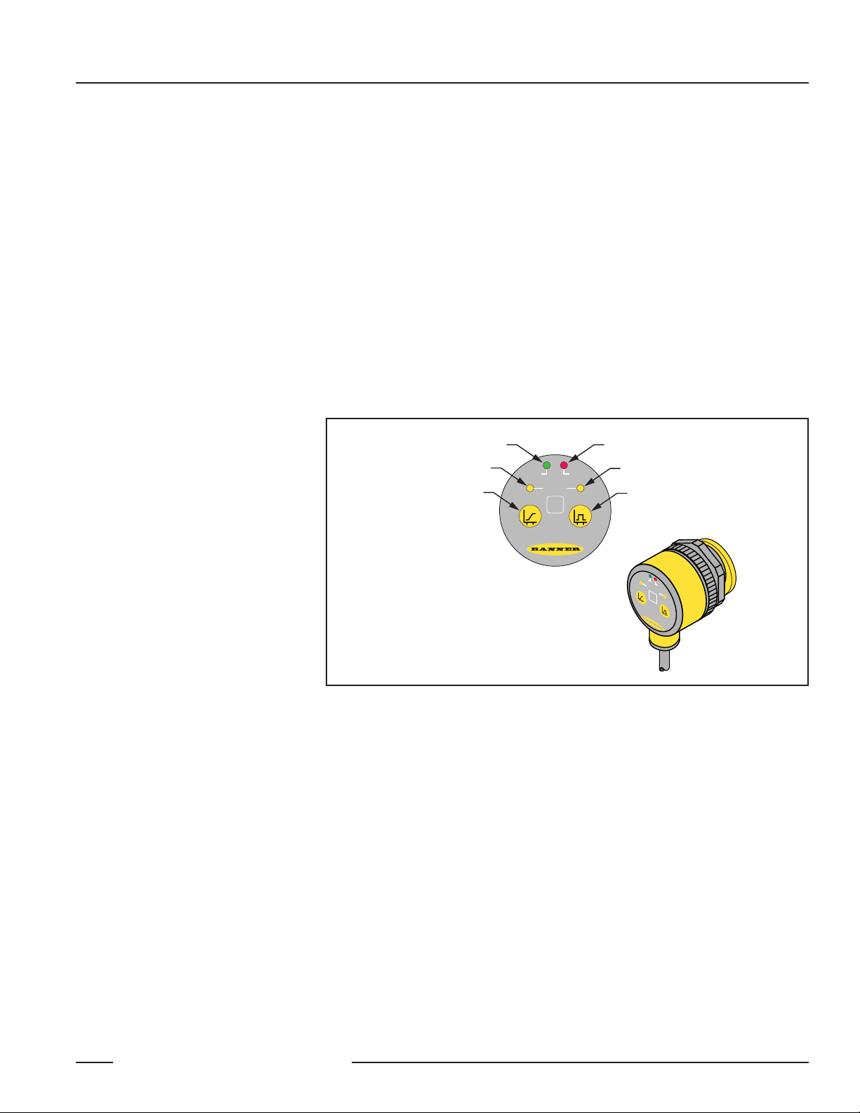
Figure 1. U-GAGE T30 Series sensor programming push buttons and indicators
General Notes on Programming:
1. The sensor will return to RUN mode if the first TEACH condition is not registered
within 120 seconds.
2. After the first limit is taught, the sensor will remain in PROGRAM mode until the
TEACH sequence is finished.
3. Press and hold the programming push button > 2 seconds (before teaching the
second limit) to exit PROGRAM mode without saving any changes. The sensor will
revert to the last saved program.
Green Power ON/OFF LED
Yellow Analog Output LED
Analog Output
Programming Push Button
POWER SIGNAL
OUTPUT
ANALOG
U-GAGE
Red Signal Strength LED
Yellow Discrete Output LED
DISCRETE
™
Discrete (Switched) Output
Programming Push Button
P
O
W
E
R
S
A
I
O
G
N
U
N
A
T
A
L
P
O
L
U
G
T
D
I
S
C
R
E
T
E
U
-
G
A
G
E
™
Page 4
U-GAGE™T30 Series with Analog and Discrete Outputs
4 P/N 57438 Rev. C
Banner Engineering Corp. • Minneapolis, MN U.S.A.
www.bannerengineering.com • Tel: 763.544.3164
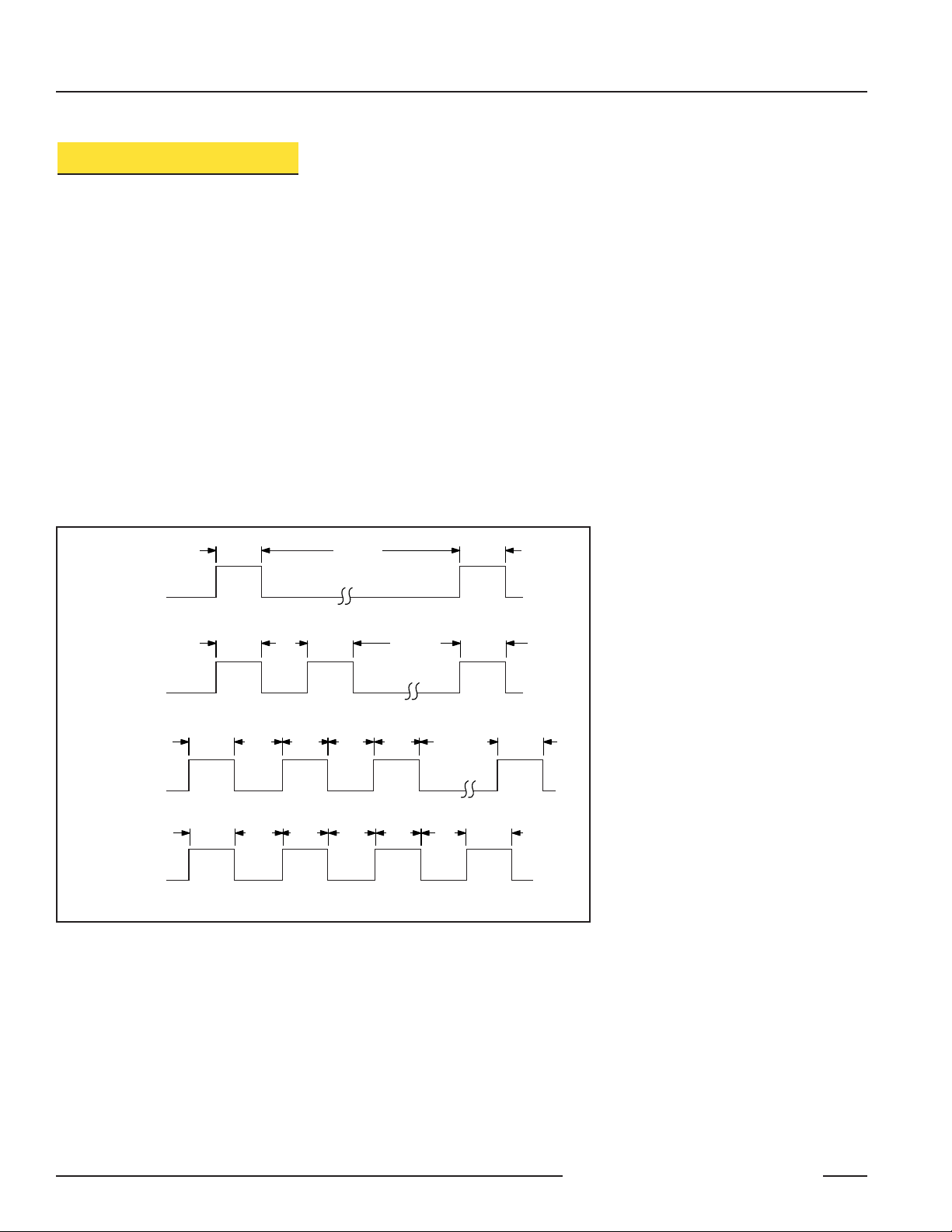
Figure 2. Timing programs for remote TEACH programming
Remote Programming
To program the sensor remotely or to disable the keypad, the Remote Programming
function may be used. Disabling the keypad prevents anyone on the production floor
from adjusting any of the programming settings. Connect the gray wire of the
sensor to +12 to 24V dc, with a remote programming switch connected between
them. NOTE: The impedance of the remote teach input is 55 kΩ.
Programming is accomplished by following the sequence of input pulses. The
duration of each pulse (corresponding to a push button “click”), and the period
between multiple pulses, are defined as: 0.04 seconds < T < 0.8 seconds.
•1 pulse: Programs first discrete limit. Wait > 0.8 sec. Next pulse programs
second discrete limit.
•2 pulses: Programs first analog limit. Wait > 0.8 sec. Next pulse programs
second analog limit.
•3 pulses: Programs first analog and discrete limit. Wait > 0.8 sec. Next pulse
programs second analog and discrete limit.
•4 pulses: Disables (locks out) or enables the keypad for security.
NOTE: Hold the Remote line high > 2 seconds (before teaching the second limit) to exit
PROGRAM mode without saving any changes. The sensor will revert to the last
saved program.
> 0.8 sec
T T
Teach First
Analog Limit
> 0.8 sec
T
Teach First Limits Teach Second Limits
T
Teach Second
Discrete Limit
Teach Second
Analog Limit
> 0.8 sec
TTT
Push Button Lockout
T
Discrete
Limits Only
Analog
Limits Only
Analog & Discrete
Together
Push Button
Lockout
T
Teach First
Discrete Limit
TT
TTTT
T TTT
0.04 sec < T < 0.8 sec
Page 5

U-GAGE™T30 Series with Analog and Discrete Outputs
P/N 57438 Rev. C 5
Banner Engineering Corp. • Minneapolis, MN U.S.A.
www.bannerengineering.com • Tel: 763.544.3164
RUN Mode
NOTE: All LED indicators momentarily go OFF when sensor changes state between
PROGRAM and RUN modes.
Signal LED
The red Signal LED indicates the strength and condition of the sensor’s incoming
signal.
Signal LED Status Indicates
OFF
No signal is received, or the target is beyond the range limitations
of the sensor (with some tolerance beyond the recommended
minimum and maximum sensing distance)
Flashing Relative received signal strength
Power ON/OFF LED Indicates
OFF Power is OFF (or in PROGRAM mode, if other LEDs are ON)
ON Solid Sensor is operating normally (power is ON, RUN mode)
Output LEDs
Each yellow Output LED lights when a target is sensed within the programmed window
limits.
Power ON/OFF LED
The green Power ON/OFF LED indicates the operating status of the sensor.
Analog Output
The U-GAGE T30 Series sensor may be programmed for either a positive or a negative
output slope, based on which condition is taught first (see Figure 3). If the near limit is
taught first, the slope will be positive; if the far limit is taught first, the slope will be
negative. Banner’s scalable analog output automatically distributes the output signal over
the width of the programmed sensing window.
The U-GAGE T30 also features a 2-second hold upon loss of the analog signal, which is
useful for harsh and unstable applications. In the event of analog signal loss for longer
than 2 seconds, the analog output goes to 3.6 mA or 0V dc, which may be used to trigger
an alarm.
Self-Diagnostic Error Mode
In the unlikely event of a microprocessor memory error, all of the LEDs will flash in
sequence. If this occurs, the setup parameters have been lost and the sensor may be
corrupt. Contact your Banner representative for further information.
Figure 3. Output current as a function of
target position
NOTE: The analog current output tracks
slightly past each window limit
(from 3.8 to 20.5 mA).
4
Near
Window
Far
Window
20
Target Position
Analog Output (mA)
Positive
Slope
Current-Sourcing Models
Flashing Discrete output is overloaded (RUN mode)
Voltage-Sourcing Models
10
Positive
Slope
Analog Output (V dc)
0
Near
Window
Target Position
Far
Window
Page 6

U-GAGE™T30 Series with Analog and Discrete Outputs
6 P/N 57438 Rev. C
Banner Engineering Corp. • Minneapolis, MN U.S.A.
www.bannerengineering.com • Tel: 763.544.3164
U-GAGE T30 Series Specifications
Proximity Mode Range
Supply Voltage Current-sourcing analog output models: 12 to 24V dc (10% max. ripple) at 90 mA, exclusive of load
Voltage-sourcing analog output models: 15 to 24V dc (10% max. ripple) at 90 mA, exclusive of load
Supply Protection Circuitry Protected against reverse polarity and transient voltages
Output Configurations Discrete (switched) output: SPST solid-state switch conducts when target is sensed within sensing
window; choose NPN (current sinking) or PNP (current sourcing) models
Analog output: Choose 0 to 10V dc sourcing or 4 to 20 mA sourcing output models; output slope may be
selected via TEACH sequence (see Window Limit Programming on pages 2-4)
Output Ratings Discrete (switched) output: 100 mA maximum
Off-state leakage current: less than 5 microamps
On-state saturation voltage: less than 1V at 10 mA and less than 1.5V at 100 mA
Analog output:
Voltage sourcing: 0 to 10V dc (at 1K ohm minimum resistance)
Current sourcing: 4 to 20 mA, 1 ohm to Rmax
Rmax = V
supply
- 7V
20 mA
Output Response Time Discrete output:
“A” suffix models: 48 milliseconds
“B” suffix models: 96 milliseconds
Analog output:
“A” suffix models: 48 milliseconds average, 16-millisecond update
“B” suffix models: 96 milliseconds average, 32-millisecond update
Sensing Performance
(Specified using a 10 cm x 10 cm
aluminum target at 25ºC under
fixed sensing conditions.)
Analog sensing resolution: ±0.25% of measured distance
Analog linearity: ±0.5% of full-scale sensing range
Sensing repeatability: ±0.25% of distance
Minimum window size: 10 mm (0.4")
Hysteresis of discrete output: 2.5 mm (0.10")
Adjustments Sensing window limits (analog or discrete): TEACH-mode programming of near and far window limits
may be set using membrane push buttons on sensor or remotely via TEACH input (see pages 2-4).
Discrete and analog window limits may be programmed separately, or together.
Analog output slope: the first limit taught is assigned to the minimum output value (4 mA or 0V)
“A” suffix models: 150 mm (5.9") min. near limit; 1 m (39") max. far limit
“B” suffix models: 300 mm (11.8") min. near limit; 2 m (79") max. far limit
Output Protection Protected against continuous overload and short-circuit; transient over-voltage; no false pulse on power-up
Indicators Four status LEDs:
In RUN mode:
Green
ON = Power ON, RUN mode
Flashing = Discrete output is overloaded
Red Flashing = Relative received signal strength
Yellow analog ON = Target is inside window limits
Yellow discrete ON = Output conducting
In Program mode:
Green OFF = PROGRAM mode
Red Flashing = Relative received signal strength
ON = Ready for first window limit
Yellow analog Flashing = Ready for second limit
OFF = Not teaching analog limits
ON = Ready for first window limit
Yellow discrete Flashing = Ready for second limit
OFF = Not teaching discrete limits
{
{
{
Page 7

U-GAGE™T30 Series with Analog and Discrete Outputs
P/N 57438 Rev. C 7
Banner Engineering Corp. • Minneapolis, MN U.S.A.
www.bannerengineering.com • Tel: 763.544.3164
U-GAGE T30 Series Specifications (continued)
Construction
Environmental Rating Leakproof design is rated IEC IP67; NEMA 6P
Molded reinforced thermoplastic polyester housing
Vibration and
Mechanical Shock
All models meet Mil. Std. 202F requirements. Method 201A (Vibration: 10 to 60Hz max., double amplitude
0.06", maximum acceleration 10G). Also meets IEC 947-5-2 requirements: 30G, 11 ms duration, half sine wave.
Operating Conditions Temperature: -20° to +70° C (-4° to 158° F)
Maximum relative humidity: 100%
Application Notes Objects passing inside the specified near limit will produce a false response.
NOTE: For more information about out-of-range and signal loss response of the analog output, see page 5.
Connections 2 m (6.5') or 9 m (30') 5-conductor PVC-covered attached cable, or 5-pin Euro-style quick-disconnect
fitting (see page 9 for optional quick-disconnect cables)
U-GAGE T30 Series Performance Curves
U-GAGE T30 Effective Beam with Plate Target (Typical)
1-Meter Models
2-Meter Models
U-GAGE T30 Effective Beam with Rod Target (Typical)
1-Meter Models
2-Meter Models
0
0 200 mm
(8.0 in)
400 mm
(16.0 in)
600 mm
(24.0 in)
800 mm
(32.0 in)
1000 mm
(40.0 in)
50 mm
50 mm
100 mm
100 mm
150 mm
150 mm
200 mm
200 mm
0
2.0 in
2.0 in
4.0 in
4.0 in
6.0 in
6.0 in
8.0 in
8.0 in
100 x 100 mm
10 x 10 mm
Width
Distance
0
0 400 mm
(16.0 in)
800 mm
(32.0 in)
1200 mm
(48.0 in)
1600 mm
(64.0 in)
2000 mm
(80.0 in)
100 mm
100 mm
200 mm
200 mm
300 mm
300 mm
400 mm
400 mm
0
4.0 in
4.0 in
8.0 in
8.0 in
12.0 in
12.0 in
16.0 in
16.0 in
100 x 100 mm
Width
Distance
0
0 200 mm
(8.0 in)
400 mm
(16.0 in)
600 mm
(24.0 in)
800 mm
(32.0 in)
1000 mm
(40.0 in)
50 mm
50 mm
100 mm
100 mm
150 mm
150 mm
200 mm
200 mm
0
2.0 in
2.0 in
4.0 in
4.0 in
6.0 in
6.0 in
8.0 in
8.0 in
25 mm Rod
10 mm Rod
Width
Distance
0
0 400 mm
(16.0 in)
800 mm
(32.0 in)
1200 mm
(48.0 in)
1600 mm
(64.0 in)
2000 mm
(80.0 in)
100 mm
100 mm
200 mm
200 mm
300 mm
300 mm
400 mm
400 mm
0
4.0 in
4.0 in
8.0 in
8.0 in
12.0 in
12.0 in
16.0 in
16.0 in
25 mm Rod
Width
Distance
Certifications
Page 8

U-GAGE™T30 Series with Analog and Discrete Outputs
8 P/N 57438 Rev. C
Banner Engineering Corp. • Minneapolis, MN U.S.A.
www.bannerengineering.com • Tel: 763.544.3164
U-GAGE T30 Series Dimensions
Cabled Models Quick-Disconnect Models
U-GAGE T30 Series Hookups
Cabled NPN
Cabled PNP
Quick-Disconnect NPN Quick-Disconnect PNP
†
4-20 mA or 0-10V dc
††
100 mA maximum
*It is recommended that the shield wire be connected to earth ground
or dc common.
ø 40.0 mm
Jam Nut
(Supplied)
M30 x 1.5
Thread
(1.57")
ø 15 mm
(0.59")
bu
bn
wh
Analog
bk
Discrete
Remote Teach
gy
shield*
45.0 mm
(1.77")
12-24V dc
†
††
51.5 mm
(2.03")
11.5 mm
(0.45")
–
+
bu
bn
wh
Analog
bk
Discrete
Remote Teach
gy
shield*
66.5 mm
(2.62 in)
–
12-24V dc
+
†
††
bu
bn
wh
bk
gy
shield*
†
Analog
††
Discrete
Remote Teach
–
12-24V dc
+
bu
bn
wh
bk
gy
shield*
†
Analog
††
Discrete
Remote Teach
–
12-24V dc
+
Page 9

U-GAGE™T30 Series with Analog and Discrete Outputs
P/N 57438 Rev. C 9
Banner Engineering Corp. • Minneapolis, MN U.S.A.
www.bannerengineering.com • Tel: 763.544.3164
Quick-Disconnect (QD) Cables
Accessories
5-Pin
Euro-style
Right-angle
with shield
5-Pin
Euro-style
Straight
with shield
MQDEC2-506
MQDEC2-515
MQDEC2-530
2 m (6.5')
5 m (15')
9 m (30')
Style Model Length Connector
MQDEC2-506RA
MQDEC2-515RA
MQDEC2-530RA
2 m (6.5')
5 m (15')
9 m (30')
Style Model
Length Connector
Mounting Brackets
SMB30A
• Angled-mount bracket
• Stainless steel
SMB1815SF
• Compact 30 mm split clamp with swivel, black
reinforced thermoplastic polyester
• Stainless steel hardware included
44 mm max.
(1.7")
ø 15 mm
(0.6")
M12 x 1
38 mm max.
(1.5")
M12 x 1
ø 15 mm
(0.6")
38 mm max.
(1.5")
45 mm
(1.8")
30°
69 mm
6.3 mm
(0.25")*
7.6 mm
(0.30")
(2.70")
R 40 mm
(1.58")
ø 6.3 mm
(0.25")*
38.5 mm
(1.52")
61 mm
(2.40")
* Use 5 mm (#10) screws to mount bracket.
Drill screw holes 40.0 mm (1.58") apart.
ø 30.5 mm
(1.20")
42.0 mm
(1.65")
36.0 mm
(1.42")
50.8 mm
(2.00")
ø15.0 mm
(0.59")
10.6 mm
(0.42")
22.9 mm
(0.9")
25.4 mm
(1.00")
Page 10

U-GAGE™T30 Series with Analog and Discrete Outputs
10 P/N 57438 Rev. C
Banner Engineering Corp. • Minneapolis, MN U.S.A.
www.bannerengineering.com • Tel: 763.544.3164
SMB30C SMB30SC
• 30 mm split clamp with swivel, black reinforced
thermoplastic polyester
• Stainless steel hardware included
• 30 mm split clamp, black reinforced thermoplastic
polyester
• Stainless steel hardware included
Mounting Brackets
56.0 mm
13.5 mm
(0.53")
63.0 mm
(2.48")
(2.20")
45.0 mm
(1.77")
31.5 mm
2.5 mm
(0.10")
(1.24")
13 mm
(0.5")
Nut Plate
M5 x 0.8
x 80 mm
Screw (2)
50.8 mm
58.7 mm
(2.31")
(2.00")
66.5 mm
(2.62")
30 x 1.5 mm
internal thread
30.0 mm
(1.18")
29.0 mm
(1.14")
12.7 mm
(0.50")
Page 11

U-GAGE™T30 Series with Analog and Discrete Outputs
P/N 57438 Rev. C 11
Banner Engineering Corp. • Minneapolis, MN U.S.A.
www.bannerengineering.com • Tel: 763.544.3164
Page 12

U-GAGE™T30 Series with Analog and Discrete Outputs
Banner Engineering Corp., 9714 Tenth Ave. No., Mpls, MN 55441 • Ph: 763.544.3164 • www.bannerengineering.com • sensors@bannerengineering.com
WARRANTY: Banner Engineering Corp. warrants its products to be free from defects for one year. Banner Engineering Corp. will repair or
replace, free of charge, any product of its manufacture found to be defective at the time it is returned to the factory during the warranty period.
This warranty does not cover damage or liability for the improper application of Banner products. This warranty is in lieu of any other warranty
either expressed or implied.
WARNING . . .
Not To Be Used for Personnel Protection
Never use these products as sensing devices for personnel protection. Doing so could lead to serious injury or death.
These sensors do NOT include the self-checking redundant circuitry necessary to allow their use in personnel safety applications.
A sensor failure or malfunction can cause either an energized or de-energized sensor output condition. Consult your current Banner Safety
Products catalog for safety products which meet OSHA, ANSI and IEC standards for personnel protection.
P/N 57438 Rev. C
!
 Loading...