

Page 1
OPPOSED
P
POLAR RETRO
FIXED-FIELD
T30 Sensors - DC-Voltage Series
0 121524 1
Self-Contained, DC-Operated Sensors
• Featuring EZ-BEAM® technology, the specially designed optics and electronics provide reliable
sensing without the need for adjustments
• “T” style plastic housing with 30 mm threaded lens in opposed, retroreflective or fixed-field
modes
• Completely epoxy-encapsulated to provide superior durability, even in harsh sensing environments rated to IP69K
• Innovative dual-indicator system takes the guesswork out of sensor performance monitoring
• Advanced diagnostics to warn of marginal sensing conditions or output overload
• 10 to 30V dc; choose SPDT (complementary) NPN or PNP outputs (150 mA max. ea.)
WARNING: Not To Be Used for Personnel Protection
Never use this device as a sensing device for personnel protection. Doing so could lead to serious
injury or death. This device does NOT include the self-checking redundant circuitry necessary to allow its
use in personnel safety applications. A sensor failure or malfunction can cause either an energized or deenergized sensor output condition.
Models
Sensing Mode Model
1
Output Range LED
T306E -
60 m (200 ft) Infrared, 950 nmT30SN6R NPN
T30SP6R PNP
T30SN6LP NPN
6 m (20 ft) Visible Red, 680 nm
T30SP6LP PNP
T30SN6FF200 NPN
200 mm (8 in) cutoff
T30SP6FF200 PNP
T30SN6FF400 NPN
400 mm (16 in) cutoff
Infrared, 880 nm
T30SP6FF400 PNP
T30SN6FF600 NPN
600 mm (24 in) cutoff
T30SP6FF600 PNP
Fixed-Field Mode Overview
T30 Series self-contained fixed-field sensors are small, powerful, infrared diffuse mode sensors with far-limit cutoff (a type of background
suppression). Their high excess gain and fixed-field technology allow detection of objects of low reflectivity, while ignoring background
surfaces. The cutoff distance is fixed. Backgrounds and background objects must always be placed beyond the cutoff distance.
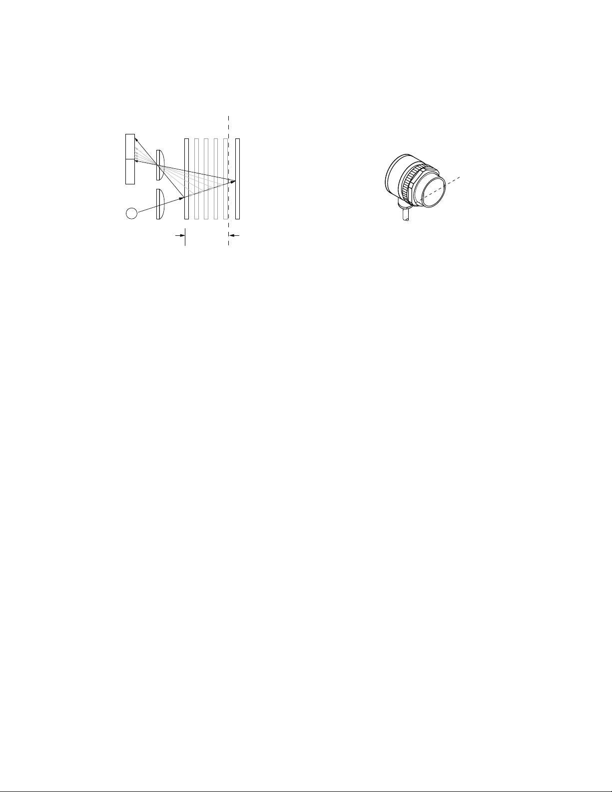
Fixed-Field Sensing – Theory of Operation
The T30FF compares the reflections of its emitted light beam (E) from an object back to the sensor’s two differently aimed detectors, R1
and R2. See Figure 1. Fixed-Field Concept on page 2. If the near detector's (R1) light signal is stronger than the far detector's (R2)
light signal (see object A in the Figure below, closer than the cutoff distance), the sensor responds to the object. If the far detector's (R2)
light signal is stronger than the near detector's (R1) light signal (see object B in the Figure below, beyond the cutoff distance), the sensor
ignores the object.
1
Standard 2 m (6.5 ft) cable models are listed. To order 9 m (30 ft) cable: add suffix W/30 (for example, T306EW/30). To order 4-pin Euro-style QD models: add suffix Q (for example,
T306EQ). A model with a QD connector requires a mating cable; see Cables on page 7.
P/N 121524 Rev. A 2/13/2013
Page 2
R1
R2
Lenses
Object
A
Object B
or
Background
Sensing
Range
Cutoff
Distance
E
Receiver
Elements
Near
Detector
Far
Detector
Emitter
Object is sensed if amount of light at R1
is greater than the amount of light at R2
Sensing
Axis
R2
R1
E
T30 Sensors - DC-Voltage Series
The cutoff distance for model T30 Series sensors is fixed at 200, 400 or 600 millimeters (7.9 in, 16.7 in, or 23.6 in). Objects lying beyond
the cutoff distance are usually ignored, even if they are highly reflective. However, under certain conditions, it is possible to falsely detect
a background object (see Background Reflectivity and Placement on page 2).
Figure 2. Fixed-Field Sensing Axis
Figure 1. Fixed-Field Concept
In the drawings and information provided in this document, the letters E, R1, and R2 identify how the sensor’s three optical elements
(Emitter “E”, Near Detector “R1”, and Far Detector “R2”) line up across the face of the sensor. The location of these elements defines the
sensing axis, see Figure 2. Fixed-Field Sensing Axis on page 2. The sensing axis becomes important in certain situations, such as those
illustrated in Figure 5. Object Beyond Cutoff - Problem on page 3 and Figure 6. Object Beyond Cutoff - Solution on page 3.
Sensor Setup
Sensing Reliability
For highest sensitivity, position the target object for sensing at or near the point of maximum excess gain. See Performance Curves on
page 5 for the excess gain curves for these sensors. Maximum excess gain for all models occurs at a lens-to-object distance of about
40 mm (1.5 in). Sensing at or near this distance makes the maximum use of each sensor’s available sensing power. The background
must be placed beyond the cutoff distance. Note that the reflectivity of the background surface also may affect the cutoff distance. Following these guidelines will improve sensing reliability.
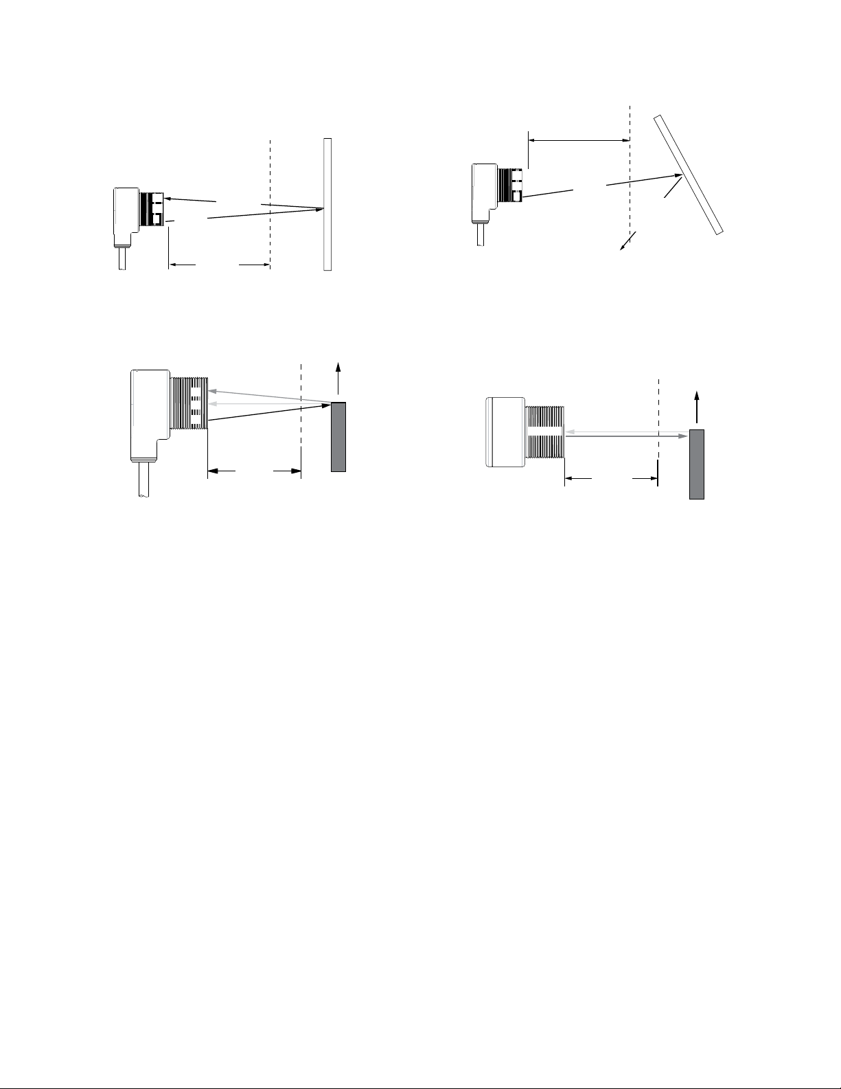
Background Reflectivity and Placement
Avoid mirror-like backgrounds that produce specular reflections. False sensor response will occur if a background surface reflects the
sensor’s light more to the near detector (R1) than to the far detector (R2). The result is a false ON condition (Figure 3. Reflective Back-
ground - Problem on page 3). To cure this problem, use a diffusely reflective (matte) background, or angle either the sensor or the
background (in any plane) so the background does not reflect light back to the sensor (Figure 4. Reflective Background - Solution on
page 3). Position the background as far beyond the cutoff distance as possible.
An object beyond the cutoff distance, either stationary (and when positioned as shown in Figure 5. Object Beyond Cutoff - Problem on
page 3), or moving past the face of the sensor in a direction perpendicular to the sensing axis, may cause unwanted triggering of the
sensor if more light is reflected to the near detector than to the far detector. The problem is easily remedied by rotating the sensor 90°
(Figure 6. Object Beyond Cutoff - Solution on page 3). The object then reflects the R1 and R2 fields equally, resulting in no false
triggering. A better solution, if possible, may be to reposition the object or the sensor.
2 www.bannerengineering.com - tel: 763-544-3164 P/N 121524 Rev. A
Page 3
E = Emitter
R1 = Near Detector
R2 = Far Detector
R2
R1
E
Fixed
Sensing
Field
Strong
Direct
Reflection
to R1
Core of
Emitted
Beam
Cutoff
Distance
Reflective
Background
T30FF
E = Emitter
R1 = Near Detector
R2 = Far Detector
R2
R1
E
Fixed Sensing Field
Strong Direct
Reflection
Away
From Sensor
Core of
Emitted
Beam
Cutoff
Distance
Reflective
Background
T30FF
Fixed
Sensing
Field
Cutoff
Distance
R1 = Near Detector
R2 = Far Detector
E = Emitter
T30FF
R1
E
R2
Reflective
Background
or
Moving Object
E = Emitter
R2 = Far Detector
R1 = Near Detector
T30FF
E, R2, R1
Fixed
Sensing
Field
Cutoff
Distance
Reflective
Background
or
Moving Object
T30 Sensors - DC-Voltage Series
Figure 3. Reflective Background - Problem
Figure 4. Reflective Background - Solution
A reflective background object in this position or moving across
the sensor face in this axis and direction may cause false sensor
response.
Figure 5. Object Beyond Cutoff - Problem
A reflective background object in this position or moving across
the sensor face in this axis will be ignored.
Figure 6. Object Beyond Cutoff - Solution
Color Sensitivity
The effects of object reflectivity on cutoff distance, though small, may be important for some applications. It is expected that at any given
cutoff setting, the actual cutoff distance for lower reflectance targets is slightly shorter than for higher reflectance targets. This behavior is
known as color sensitivity.
For example, an excess gain of 1 (see Performance Curves on page 5) for an object that reflects 1/10 as much light as the 90% white
card is represented by the horizontal graph line at excess gain = 10. An object of this reflectivity results in a far limit cutoff of approximately 190 mm (7.5 in) for the 200 mm (8 in) cutoff model, for example; thus 190 mm represents the cutoff for this sensor and target.
These excess gain curves were generated using a white test card of 90% reflectance. Objects with reflectivity of less than 90% reflect
less light back to the sensor, and thus require proportionately more excess gain in order to be sensed with the same reliability as more
reflective objects. When sensing an object of very low reflectivity, it may be especially important to sense it at or near the distance of
maximum excess gain.
P/N 121524 Rev. A www.bannerengineering.com - tel: 763-544-3164 3
Page 4
T30 Sensors - DC-Voltage Series
Specifications
Supply Voltage and Current
10 to 30V dc (10% max. ripple); supply current (exclusive of load current):
Emitters, Non-Polarized, Retro: 25 mA
Receivers: 20 mA
Polarized Retroreflective: 30 mA
Fixed-Field: 35 mA
Supply Protection Circuitry
Protected against reverse polarity and transient voltages
Output Configuration
SPDT solid-state dc switch; NPN (current sinking) or
PNP (current sourcing) outputs, depending on model
Light Operate: N.O. output conducts when sensor
sees its own (or the emitter’s) modulated light
Dark Operate: N.C. output conducts when the sensor
sees dark; the N.C. output may be wired as a normally
open marginal signal alarm output, depending upon
hookup to power supply
Output Rating
150 mA maximum (each) in standard hookup. When
wired for alarm output, the total load may not exceed
150 mA.
OFF-state leakage current: < 1 µA at 30V dc
ON-state saturation voltage: < 1V at 10 mA dc; <
1.5V at 150 mA dc
Output Protection Circuitry
Protected against false pulse on power-up and continuous overload or short circuit of outputs
Output Response Time
Opposed mode: 3 ms ON, 1.5 ms OFF
Retro, Fixed-Field and Diffuse: 3 ms ON and OFF
NOTE: 100 ms delay on power-up;
outputs do not conduct during this
time.
Repeatability
Opposed mode: 375 μs
Retro, Fixed-Field and Diffuse: 750 μs
Repeatability and response are independent of signal
strength.
Indicators
Two LEDs (Green and Yellow)
Green ON steady: power to sensor is ON
Green flashing: output is overloaded
Yellow ON steady: N.O. output is conducting
Yellow flashing: excess gain marginal (1 to 1.5x) in
light condition
Construction
PBT polyester housing; polycarbonate (opposed-mode)
or acrylic lens
Environmental Rating
Leakproof design rated NEMA 6P, DIN 40050 (IP69K)
Connections
2 m (6.5 ft) or 9 m (30 ft) attached cable or 4-pin Eurostyle quick-disconnect fitting
Operating Conditions
Temperature: −40° to +70° C (−40° to +158° F)
Humidity: 90% at +50° C maximum relative humidity
(non-condensing)
Vibration and Mechanical Shock
All models meet Mil. Std. 202F requirements. Method
201A (Vibration; frequency 10 to 60 Hz, max., double
amplitude 0.06 in acceleration 10G). Method 213B conditions H&I (Shock: 75G with unit operating; 100G for
non-operation)
Certifications
4 www.bannerengineering.com - tel: 763-544-3164 P/N 121524 Rev. A
Page 5

75 m
(250')
60 m
(200')
45 m
(150')
30 m
(100')
15 m
(50')
0
0
250 mm
500 mm
750 mm
250 mm
500 mm
750 mm
0
10"
20"
30"
10"
20"
30"
DISTANCE
T30 Series
Opposed Mode
7.5 m
(25')
6.0 m
(20')
4.5 m
(15')
3.0 m
(10')
1.5 m
(5')
0
0
50 mm
100 mm
150 mm
50 mm
100 mm
150 mm
0
2"
4"
6"
2"
4"
6"
DISTANCE
T30 Series
Polarized Retro
with BRT-3 Reflector
1
10
100
1 m
(3.3')
10 m
(33')
100 m
(330')
0.1 m
(0.33')
1000
E
X
C
E
S
S
G
A
I
N
DISTANCE
T30 Series
Opposed Mode
1
10
100
0.1 m
(0.33')
1 m
(3.3')
10 m
(33')
0.01 m
(0.033')
1000
E
X
C
E
S
S
G
A
I
N
DISTANCE
T30 Series
Polarized Retro
with BRT-3 Reflector
T30 Sensors - DC-Voltage Series
Performance Curves
Table 1: Beam Pattern
Table 2: Excess Gain
Opposed Polarized Retro
Opposed Polarized Retro
2
2
P/N 121524 Rev. A www.bannerengineering.com - tel: 763-544-3164 5
2
Performance based on use of a model BRT-3 retroreflector (3 in. diameter). Actual sensing range may be more or less than specified, depending on the efficiency and reflective area of the
retroreflector used.
Page 6

1
10
100
10 mm
(0.4")
100 mm
(4")
1000 mm
(40")
1 mm
(0.04")
E
X
C
E
S
S
G
A
I
N
DISTANCE
1000
T30 Series
Fixed-field mode
with 200 mm far
limit cutoff
1
10
100
10 mm
(0.4")
100 mm
(4")
1000 mm
(40")
1 mm
(0.04")
E
X
C
E
S
S
G
A
I
N
DISTANCE
1000
T30 Series
Fixed-field mode
with 400 mm far
limit cutoff
1
10
100
10 mm
(0.4")
100 mm
(4")
1000 mm
(40")
1 mm
(0.04")
E
X
C
E
S
S
G
A
I
N
DISTANCE
1000
T30 Series
Fixed-field mode
with 600 mm far
limit cutoff
Jam Nut
(Supplied)
M30 x 1.5
Thread
ø 15 mm
(0.59")
ø 40.0 mm
(1.57")
45.0 mm
(1.77")
51.5 mm
(2.03")
11.5 mm
(0.45")
66.5 mm
(2.62")
Green LED
Power Indicator
Yellow LED
Output Indicator
bn
bu
10-30V dc
+
–
bn
bu
wh
bk
+
10 - 30V dc
–
Load
Load
bu
bn
wh
bk
+
10 - 30V dc
–
Load
Load
T30 Sensors - DC-Voltage Series
Table 3: Excess Gain
Performance based on use of a 90% reflectance white test card. Focus and spot sizes are typical.
Fixed-Field – 200 mm Fixed-Field – 400 mm Fixed-Field – 600 mm
Ø 16 mm spot size at 35 mm focus
Ø 20 mm spot size at 200 mm cutoff
Using 18% gray test card: cutoff distance
will be 95% of value shown.
Using 6% black test card: cutoff distance
will be 90% of value shown.
Dimensions
Cabled Models
Ø 17 mm spot size at 35 mm focus
Ø 25 mm spot size at 400 mm cutoff
Using 18% gray test card: cutoff distance
will be 90% of value shown.
Using 6% black test card: cutoff distance
will be 85% of value shown.
Ø 17 mm spot size at 35 mm focus
Ø 30 mm spot size at 600 mm cutoff
Using 18% gray test card: cutoff distance
will be 85% of value shown.
Using 6% black test card: cutoff distance
will be 75% of value shown.
QD Models
Hookups
Cabled Emitters
6 www.bannerengineering.com - tel: 763-544-3164 P/N 121524 Rev. A
NPN (Sinking) Outputs Standard Hookup
PNP (Sourcing) Outputs Standard Hookup
Page 7
10 - 30V dc
no connection
bu
bk
bn
wh
+
–
bu
bn
wh
bk
10 - 30V dc
Load
Alarm
+
–
bu
bn
wh
bk
10 - 30V dc
Load
+
–
Alarm
44 Typ.
ø 14.5
M12 x 1
2
3
4
1
32 Typ.
[1.26"]
30 Typ.
[1.18"]
ø 14.5 [0.57"]
M12 x 1
T30 Sensors - DC-Voltage Series
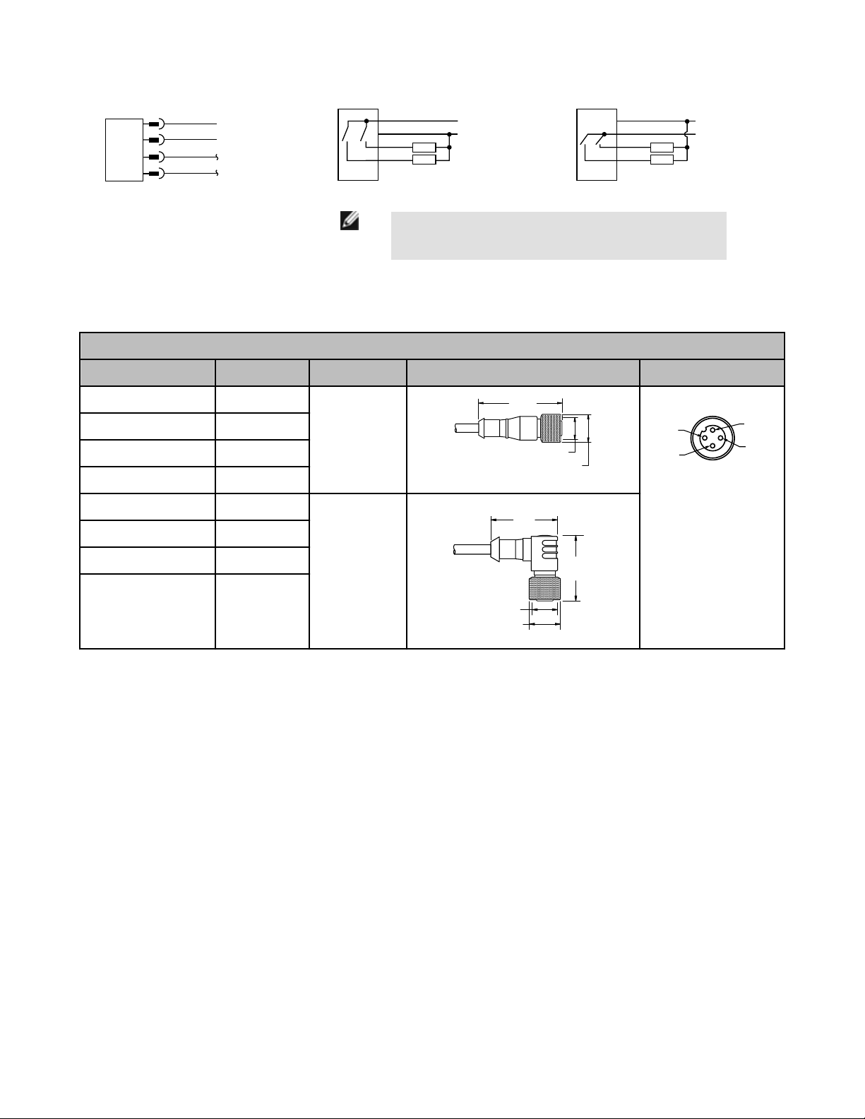
QD Emitters
Cables
4-Pin Threaded M12/Euro-Style Cordsets
Model Length Style Dimensions Pinout
MQDC-406 1.83 m (6 ft)
MQDC-415 4.57 m (15 ft)
MQDC-430 9.14 m (30 ft)
MQDC-450 15.2 m (50 ft)
MQDC-406RA 1.83 m (6 ft)
MQDC-415RA 4.57 m (15 ft)
MQDC-430RA 9.14 m (30 ft)
MQDC-450RA 15.2 m (50 ft)
NPN (Sinking) Outputs Alarm Hookup
NOTE: Cabled hookups are shown. QD hookups are function-
Straight
Right-Angle
PNP (Sourcing) Outputs Alarm Hookup
ally identical.
1 = Brown
2 = White
3 = Blue
4 = Black
Banner Engineering Corp Limited Warranty
Banner Engineering Corp. warrants its products to be free from defects in material and workmanship for one year following the date of
shipment. Banner Engineering Corp. will repair or replace, free of charge, any product of its manufacture which, at the time it is returned
to the factory, is found to have been defective during the warranty period. This warranty does not cover damage or liability for misuse,
abuse, or the improper application or installation of the Banner product.
THIS LIMITED WARRANTY IS EXCLUSIVE AND IN LIEU OF ALL OTHER WARRANTIES WHETHER EXPRESS OR IMPLIED (INCLUDING, WITHOUT LIMITATION, ANY WARRANTY OF MERCHANTABILITY OR FITNESS FOR A PARTICULAR PURPOSE), AND
WHETHER ARISING UNDER COURSE OF PERFORMANCE, COURSE OF DEALING OR TRADE USAGE.
This Warranty is exclusive and limited to repair or, at the discretion of Banner Engineering Corp., replacement. IN NO EVENT SHALL
BANNER ENGINEERING CORP. BE LIABLE TO BUYER OR ANY OTHER PERSON OR ENTITY FOR ANY EXTRA COSTS, EXPENSES, LOSSES, LOSS OF PROFITS, OR ANY INCIDENTAL, CONSEQUENTIAL OR SPECIAL DAMAGES RESULTING FROM ANY
PRODUCT DEFECT OR FROM THE USE OR INABILITY TO USE THE PRODUCT, WHETHER ARISING IN CONTRACT OR WARRANTY, STATUTE, TORT, STRICT LIABILITY, NEGLIGENCE, OR OTHERWISE.
Banner Engineering Corp. reserves the right to change, modify or improve the design of the product without assuming any obligations or
liabilities relating to any product previously manufactured by Banner Engineering Corp.
 Loading...