

Page 1
Sonic OMNI-BEAM
™
Switched or
Analog output
Piezoelectric Ultrasonic Proximity Sensors
Short-range ultrasonic proximity detection from 4 to 26 inches
•
True windowing, with reliable near-limit cutoff; both position and size
•
of the sensing window are quickly and easily adjusted
Exclusive moving-dot LED indicator for visual display of relative
•
target position within the sensing window
Relay output models are programmable for either ON/OFF presence
•
detection or HIGH/LOW level control
Analog output models source 0 to +10V dc, positive or negative slope,
•
between the limits of the sensing window
Relay output models allow adjustment of sensor response to specific
•
target characterisitics to reduce false signals and nuisance signal loss
Piezoelectric transducer is protected from hostile environments by
•
a KAPTON® polyimide film seal; sensors are fully-gasketed
OSBUSR
Sensor Block
OPB Series
Power Block
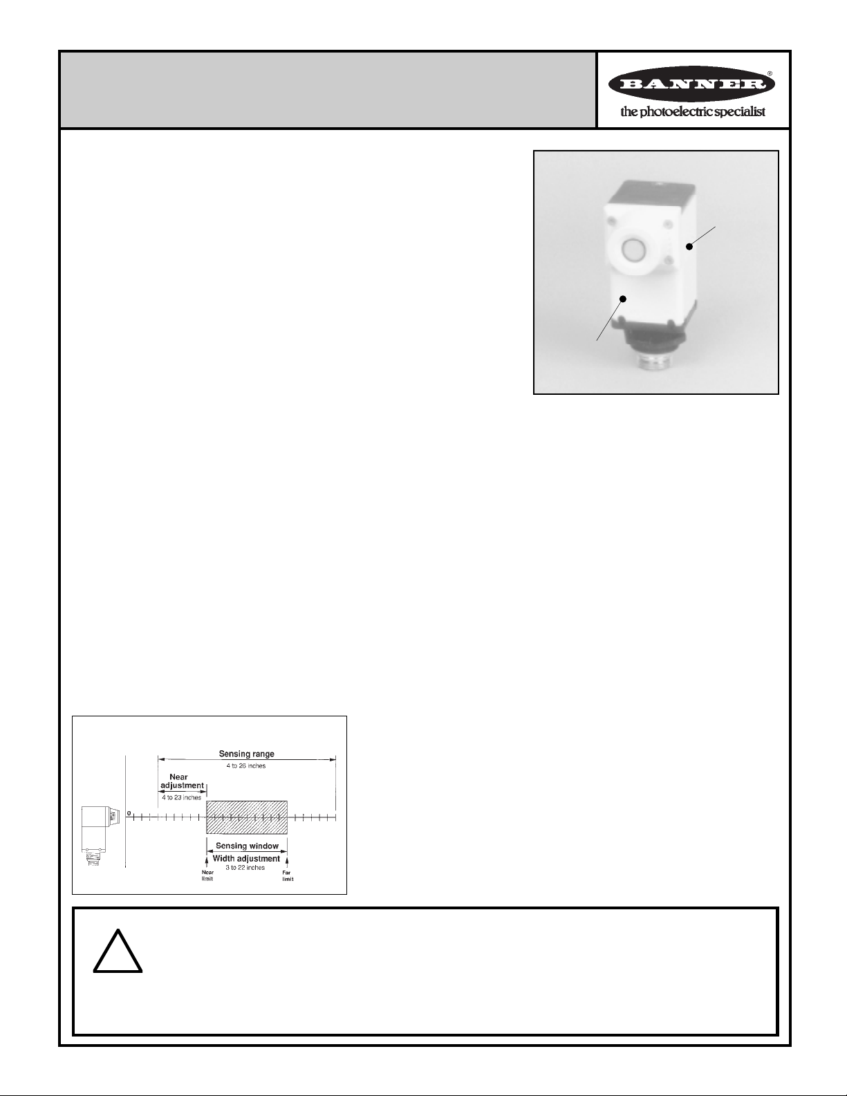
Banner's Sonic OMNI-BEAM™ piezoelectric ultrasonic proximity sensors detect targets
within an adjustable sensing "window" (see diagram, below). These sensors feature true
windowing, with reliable near-limit cutoff. Both the location and size of the window are
easily adjusted within the sensor's 4 to 26-inch range. A Sonic OMNI-BEAM sensor
consists of a sensor block module and a power block module. All models use the model
OSBUSR sensor block module. A compatible power block is chosen on the basis of
operating voltage and output type. Power block modules are available either with a form
"C" SPDT electromechanical output relay or with solid-state analog voltage sourcing
outputs. Models are listed on page 3.
A ten-element array of LED indicators, built into the top of the OSBUSR sensor block
module, visually displays the relative position of a target within the sensing window. This
moving-dot target position indicator makes initial setup fast and easy, and provides a
continuous visual display of sensor performance. Sensor operating status is fully displayed
by separate LED indicators for TARGET PRESENT (anywhere within the 4 to 26-inch
sensing range) and LOAD (electromechanical output relay) energized.
Relay output power block modules may be programmed for either of two control modes.
In the ON/OFF control mode, the output relay is energized whenever a target object is
detected within the sensing window. The second control mode, the HIGH/LOW mode,
provides the switching logic required for fill-level or web tensioning (loop) control. In the
HIGH/LOW mode, the output relay is energized when the target moves beyond the far limit
of the sensing window, but does
Sensing Window Concept
not de-energize until the target
reaches the near limit. The
relay energizes again when the
target passes the far limit. Operating mode selection is done
via a switch inside the model
OSBUSR sensor head. When a
relay-output power block is used,
the 10-element LED display indicates the relative position of
a target within the sensing window.
Analog voltage sourcing power block modules
have two separate voltage sourcing solid-state outputs: 0 to +10V dc and +10 to 0V dc. Maximum load
current is 10 mA per output. Outputs of dc-operated
models are useable simultaneously (see specs).
Output voltage is proportional to the distance from
the sensor face to a target object detected within the
sensing window. This relationship between target
distance and analog voltage output may be either
positive or negative, depending upon which of the
power block outputs is used. When using the "negatively sloped" output, power block output is +10V dc
at the near window limit and decreases to 0V dc at the
far limit. The "positively sloped" output increases
from 0V dc at the near limit to +10V dc at the far
window limit. When an analog power block is used,
the 10-element LED display indicates the relative
position of a target object within the sensing window
and the approximate power block output voltage.
When a relay output power block is used, sensor
response is programmable by selecting the number
of consecutive sensing cycles that are required to
verify the presence (or absence) of a target before the
sensor's output is allowed to change state. The
sensor may be programmed to "wait" 1, 3, 10, or 30
consecutive sensing cycles. This useful feature may
be used to "smooth" sensor response by preventing
false response to nuisance signals or to intermittent
signal loss. The sensor can also be adjusted for faster
response (shorter "wait") when required. Sensor
response programming is done via easily-accessible
DIP switches located inside the base of the sensor
head. The response time programming feature is not
operative when an analog power block is used.
WARNING These ultrasonic presence sensors do NOT include the self-checking redundant circuitry necessary to allow their use
in personnel safety applications. A sensor failure or malfunction can result in either an energized or a de-energized sensor output
!
Only MACHINE-GUARD and PERIMETER-GUARD Systems, and other systems so designated, are designed to meet OSHA and ANSI machine safety
standards for point-of-operation guarding devices. No other Banner sensors or controls are designed to meet these standards, and they must NOT be
used as sensing devices for personnel protection.
Printed in USA
condition.
Never use these products as sensing devices for personnel protection. Their use as safety devices may create an unsafe condition which
could lead to serious injury or death.
P/N 03536D4B
Page 2
Sonic OMNI-BEAM
The piezoelectric transducer must remain clean and dry for reliable
sensing. A KAPTON® film seal protects the transducer from
splash and vapor of water and most chemicals, solvents, lubricants, and fuels. Sensor block and power block housings are
molded from tough, corrosion-proof VALOX® thermoplastic
polyester. Indicator LEDs are viewed through a gasketed, transparent Lexan® top cover. Power block modules are totally epoxyencapsulated for maximum reliability. When assembled, all
components are fully gasketed.
Power blocks are available either with 6 feet of PVC-covered
cable attached or with an integral "QD" (Quick Disconnect)
connector. Mating industrial-duty 12-foot minifast™ quickdisconnect cables are sold separately. A stainless steel mounting bracket (model SMB30MM) is also available (below).
The model OSBUSR sensor block and the various power block
modules must be purchased individually. See the next page
to select a power block module appropriate to your needs.
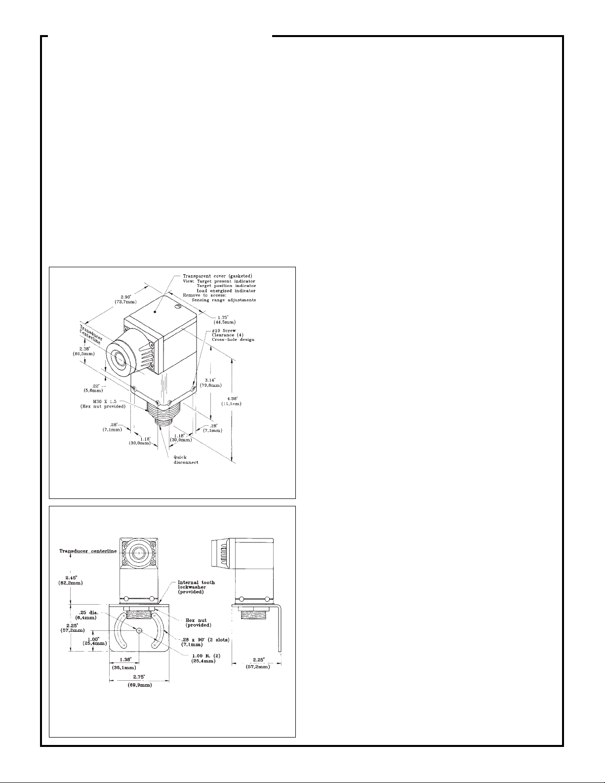
Dimensions
The model OSBUSR sensor head module and the power block
module are sold separately.
Model SMB30MM Mounting Bracket
Accessory mounting bracket model SMB30MM has curved mounting slots
for versatility in sensor mounting and orientation. OMNI-BEAM™ family
sensors mount to the bracket by their threaded base, using a jam nut and
lockwasher (both supplied). The curved mounting slots have clearance for
1/4-inch screws. Bracket material is 11-gauge stainless steel.
Specifications
SUPPLY VOLTAGE:
Relay output power blocks
+18 to 30V dc
105 to 130V ac (50/60Hz)
210 to 250V ac (50/60Hz)
Analog output power blocks
+15 to 30V dc
105 to 130V ac (50/60Hz)
210 to 250V ac (50/60Hz)
SENSING RANGE: 4 to 26 inches (10 to 66cm).
WINDOW SIZE: 3 to 22 inches (8 to 56cm) in depth, adjustable.
LIMIT ADJUSTMENTS (all models): near and far window limits
are independently adjustable using 15-turn clutched potentiometers
(with slotted brass elements), located beneath a gasketed cover on top
of the sensor. A small, flat-bladed screwdriver is required for adjustment. NOTE: Always set near limit first (by adjusting the NEAR
control); the far limit is set by adjusting the WIDTH control.
OPERATING MODES:
With relay output power block
1) ON/OFF mode. Output relay energizes when
target is within the sensing window.
2) HIGH/LOW mode. Output relay energizes when
target moves beyond the far limit, and de-energizes
when target moves inside the near limit.
With analog output power block
Power block analog voltage output is proportional to the position
of a target object detected within the sensing window. The relationship between the 0 to 10V dc analog voltage output and target
distance is selectable, and may be either positive or negative.
STATUS INDICATORS:
With relay output power block
LED indicators for TARGET PRESENT and LOAD (relay energized). Ten-element moving-dot display indicates relative
position of the target within the sensing window.
With analog output power block
LED indicators for TARGET PRESENT. Ten-element movingdot display indicates relative position of the target within the
sensing window and approximate analog voltage output.
RESPONSE TIME:
With relay output power block
programmable for 1, 3, 10 or 30 consecutive sensing cycles for target
presence/absence verification (25ms/cycle).
With analog output power block, 25 milliseconds
OUTPUT:
Relay output power blocks
One form "C" SPDT relay, silver nickel alloy contacts.
Maximum voltage: 250V ac or 30V dc (resistive load)
Maximum current: 7 amps (resistive load)
Minimum load: 5V dc at 10 milliamps
Mechanical life: 50,000,000 operations
Electrical life: 100,000 operations (at full-rated resistive load)
Analog output power blocks
Two solid-state outputs: 0 to +10V dc sourcing and +10 to 0V dc
sourcing. Outputs may be used simultaneously. Maximum load
for dc powered models is 10mA each output. Outputs of ac powered models may also be used simultaneously, but total load may
not exceed 10mA. Protected against short-circuit and overload.
OUTPUT CONNECTOR: 6-foot attached PVC-covered cable, or
integral threaded standard quick-disconnect connector. Twelve-foot
long mating quick-disconnect cables are sold separately (next page).
CONSTRUCTION: Housing: molded VALOX
ester. Top view window: transparent Lexan® polycarbonate.
Sensor seal: KAPTON® polyimide type HN film. Hardware: stainless
steel. When assembled, all components are fully gasketed and rated
NEMA 4.
OPERATING TEMP: 0 to 50°C (+32 to 122°F).
HUMIDITY: 90% maximum relative humidity (non-condensing).
KAPTON is a registered trademark of Dupont Co.
VALOX and Lexan are registered trademarks of General Electric Co.
®
thermoplastic poly-
2
Page 3

Sonic OMNI-BEAM
Selecting a Power Block Module
A power block module performs the dual functions of providing the proper operating voltage for the sensor block and of interfacing the sensor
block to the circuit to be controlled. See Specifications for information on power block output load capacity. Below is a list of power block
modules that may be used with the Sonic OMNI-BEAM OSBUSR sensor block module. Sensor block (OSBUSR) and power block must be
ordered separately.
Model Output(s) Required supply voltage Cable Type
OPBA5 form "C" SPDT electromechanical relay 105 to 130V ac (50/60 Hz) 6-ft. 5-conductor PVC-covered cable
OPBA5QD form "C" SPDT electromechanical relay 105 to 130V ac (50/60 Hz) MBCC-512 cable required (see below)
OPBB5 form "C" SPDT electromechanical relay 210 to 250V ac (50/60 Hz) 6-ft. 5-conductor PVC-covered cable
OPBB5QD form "C" SPDT electromechanical relay 210 to 250V ac (50/60 Hz) MBCC-512 cable required (see below)
OPBT5 form "C" SPDT electromechanical relay 18-30V dc, 100mA max. 6-ft. 5-conductor PVC-covered cable
OPBT5QD form "C" SPDT electromechanical relay 18-30V dc, 100mA max. MBCC-512 cable required (see below)
OPBA3 analog solid-state voltage sourcing (2) 105 to 130V ac (50/60 Hz) 6-ft. 5-conductor PVC-covered cable
OPBA3QD analog solid-state voltage sourcing (2) 105 to 130V ac (50/60 Hz) MBCC-512 cable required (see below)
OPBB3 analog solid-state voltage sourcing (2) 210 to 250V ac (50/60 Hz) 6-ft. 5-conductor PVC-covered cable
OPBB3QD analog solid-state voltage sourcing (2) 210 to 250V ac (50/60 Hz) MBCC-512 cable required (see below)
OPBT3 analog solid-state voltage sourcing (2) 15 to 30V dc, 100mA max.6-ft. 4-conductor PVC-covered cable
OPBT3QD analog solid-state voltage sourcing (2) 15 to 30V dc, 100mA max.MBCC-412 cable required (see below)
Hookup Information: OPBA5, OPBA5QD, OPBB5,
OPBB5QD, OPBT5, OPBT5QD
Electromechanical Relay Output Power Blocks
*Models OPBT5 and OPBT5QD: BROWN wire = +V dc; BLUE = dc common.
Functional Diagram: Sensors with Electromechanical
Relay Output
Hookup Information: OPBA3, OPBA3QD, OPBB3,
OPBB3QD Analog Output Power Blocks
Hookup Information: OPBT3 and OPBT3QD
Analog Output Power Blocks
External Power**
**External Power: 105-130V ac, 210-250V ac, or +18 to 30V dc, depending upon power block
model (table, above). Models OPBT5, OPBT5QD: BROWN wire = +V dc; BLUE = dc common.
Power Block Module
(electromechanical
relay output)
NOTE: If both outputs are used simultaneously, the maximum load per
output may not exceed 10 mA.
minifast™ QD Cables for QD model power blocks (purchase cables separately; see table above)
MBCC-512 Cable connector
Bottom view of power block
Side view of connector
(both models):
MBCC-412 Cable connector
Bottom view of power block
3
Page 4

Adjustment Information
Power Blocks with ELECTROMECHANICAL RELAY Output
Two operating parameters are programmable via a set of four DIP switches located at the base
of the sensor head (see photo, right). The four captive screws that fasten the sensor head to the
power block are loosened to gain access to the switches. The switches may be flipped up ("on")
or down ("off") using the tip of a ballpoint pen or a small screwdriver. See drawing below.
Switches #1, #2, and #3 select the number of consecutive sensing cycles required for target
presence or absence verification. This feature enables the sensor to be adjusted for smooth
response in any sensing application:
All switches "off" = 1 cycle (25ms response)
Switch #1 "on" = 3 cycles More than 1 switch "on" = (cycle count
Switch #2 "on" = 10 cycles is additive)
Switch #3 "on" = 30 cycles Factory setting is switch #1 "on" = 3 cycles
Switch #4 selects the output control mode. Switch #4 "on" = ON/OFF mode (factory setting).
Switch #4 "off" = HIGH/LOW mode.
Sensing Window Adjustment
The LOAD indicator LED is used to locate and "size" the sensing window. The NEAR limit and
window WIDTH adjustments are 15-turn potentiometers, clutched at both ends of travel. They
are adjusted using a small, flat-blade screwdriver. Clockwise rotation of the NEAR limit
adjustment moves the near window limit farther away from the sensor, and counterclockwise
rotation moves the near window limit closer to the sensor. Clockwise rotation of the window
WIDTH adjustment increases the size of the sensing window; counterclockwise rotation
decreases the size of the sensing window. The window adjustment procedure is slightly different
for each control mode. NOTE: the TARGET PRESENT indicator LED lights whenever a target
is sensed anywhere within the 4 to 26-inch sensing range, regardless of the window adjustments.
The factory settings are:
NOTE: With the NEAR limit control fully counterclockwise, the sensing window width is
referenced to the sensor face (zero inches). With these limit settings, and with switch #4 at its
factory setting for ON/OFF operation, the unit will function as a presence detector over its full
sensing range (i.e. the output relay will be energized whenever a target is sensed within the
sensor's 4 to 26-inch range). The window adjustment procedures discussed below begin with
these factory settings.
NEAR limit = control fully counterclockwise
window WIDTH = 26 inches
Window adjustment for the ON/OFF output control mode
(programming switch #4 "on"):
1) Position the target material at the desired near limit of the sensing window. Rotate the
NEAR limit control clockwise to find the point where the load indicator just turns "off".
2) Move the target material to the desired far limit of the sensing window and rotate the window WIDTH control counterclockwise to find
the point at which the LOAD indicator just turns "off".
3) Reposition the target at the near window limit and readjust the NEAR limit control (if necessary) to re-establish the switching point.
4) Check the far window limit if any adjustments where made in step #3. Readjust the window WIDTH control, if necessary.
5) The moving-dot LED display will confirm the window dimensions by indicating the relative position of the target within the
established window, in 10% increments.
Window adjustment for the HIGH/LOW output control mode (programming switch #4 "off"):
1) Remove all objects within the sensing range. The TARGET PRESENT indicator should be "off"; the LOAD indicator should be "on".
2) Position the target material at the desired near limit of the sensing window. Rotate the NEAR limit control clockwise to find the point
at which the LOAD indicator just turns "off".
3) While keeping the target within the sensing field (TARGET PRESENT indicator always "on"), carefully move the target to the desired
far window limit. Then rotate the window WIDTH control counterclockwise to find the point at which the LOAD indicator just turns "on".
4) Reposition the target at the near limit and readjust the NEAR limit control, if necessary, to re-establish the switching point.
5) Check the far limit if any adjustments where made in step #3. Readjust the window WIDTH control, if necessary.
APPLICATION NOTES (see also page 6)
1) The sensing pattern is narrow. Flat targets must be parallel to the face of the sensor to within +/-3 degrees (depending upon target reflectivity).
2) The transducer is protected by a KAPTON
3) Sensing at less than 4 inches from the face of the transducer is not reliable.
®
film. However, the transducer must be kept clean and dry during operation.
4
Page 5

Adjustment Information
e
e
Power Blocks with ANALOG Output
The programming DIP switches inside the OSBUSR sensor block have
no effect when using analog power blocks. The only adjustments are to
the NEAR and WIDTH potentiometers. Note: The status of the LOAD
indicator LED should be disregarded when a sensor with an analog
power block is being adjusted.
Sensing Window Adjustment
A dc voltmeter is used to locate and to "size" the sensing window. The
NEAR and FAR limit adjustments on top of the sensor head (see photo
on page 4) are 15-turn potentiometers, clutched at both ends of travel.
They are adjusted using a small, flat-blade screwdriver. Clockwise
rotation of either limit adjustment moves that window limit farther
away from the sensor. Counterclockwise rotation moves that limit
closer to the sensor.
Refer to the hookup drawings for ANALOG output power blocks on
page 3. If the positively-sloped power block output (black wire) is used,
the analog value of the output increases from 0 to +10 volts dc as the
sensor-to-target distance increases. If the negatively-sloped power
block output (white wire) is used, the analog value of the output
decreases from +10 to 0 volts as the sensor-to-target distance increases.
The window width may be set at from 3 inches to 22 inches. This
sensing window may be placed anywhere within the 4 to 26 inch sensing
range of the OSBUSR sensor block. NOTE: The NEAR limit may be
referenced as close as zero inches (i.e. zero inches equals zero volts or
+10 volts output); however, sensing is not reliable within the first 4
inches from the transducer face.
Sonic OMNI-BEAM Analog Outputs
The graphs below show the relationship between the target object
position within the sensing window, the number of LED array
indicators "on", and the analog dc voltage output for sonic
OMNI-BEAM sensor block module model OSBUSR used with
one of the following analog power block modules: OPBA3,
OPBA3QD; OPBB3, OPBB3QD; OPBT3, OPBT3QD. Graphs
for both positive slope and negative slope output are shown.
Positive slope:
output voltage increases with target distance
10
9
8
Position Indicator
7
LEDs
6
5
4
3
Output (V dc)
2
1
1
0
Positive slop
7
6
5
4
3
2
10
9
8
The factory settings are:
Near limit (NEAR control) = 0 inches
Far limit (WIDTH control) = 26 inches
With these settings, the voltage at the minimum sensing range (4 inches)
will be approximately 1.6V dc (positive slope selected) or 9.4V dc
(negative slope selected).
Window adjustment procedure:
1) Remove the transparent plastic top cover of the sensor head for
access to the NEAR and WIDTH adjustments. Connect a dc voltmeter
across either the black and yellow wires or the white and yellow wires
of the cable (depending upon the output to be used) with or without the
load connected. Connect the brown and blue power supply wires from
the cable to a suitable power source and apply power.
2) Position the target material at the desired near limit of the sensing
window. Rotate the NEAR limit control to the point where the output
voltage just equals 0.0 V dc (black and yellow output wires in use,
positive slope) or 10.0V dc (white and yellow output wires used,
negative slope). For positive slope adjustment, rotate the control
clockwise to decrease the voltage; rotate counterclockwise to increase
the voltage. For negative slope adjustment, rotate counterclockwise to
decrease and clockwise to increase.
3) Move the target material to the desired far limit of the sensing
window and rotate the WIDTH control to find the point at which the
output voltage just equals 10.0 V dc (positive slope) or 0.0V dc
(negative slope). For positive slope adjustment, rotate the control
clockwise to decrease the voltage; rotate counterclockwise to increase
the voltage. For negative slope adjustment, rotate counterclockwise to
decrease and clockwise to increase.
Sensing Window Width
Near Limit
Negative slope:
output voltage decreases with target distance
10
10
9
8
7
6
5
4
3
Output (V dc)
2
1
0
Near Limit
Negative slop
9
8
7
6
Position Indicator
LEDs
5
4
Sensing Window Width
3
2
Far Limit
1
Far Limit
4) Reposition the target material at the near limit and readjust the
NEAR limit control, if necessary, to re-establish the correct dc output
(repeat step #2).
5) If any adjustment was necessary in step #4, recheck the far limit and
readjust the WIDTH control (repeat step #3), if necessary.
6) The moving-dot LED display will confirm the window dimensions by indicating the relative position of the target within the
established window, in 10% increments.
5
Page 6

BASIC THEORY OF ULTRASONIC SENSING
Ultrasonics are sound waves of frequencies above the range of human
hearing. In sonic OMNI-BEAM™ sensors, ultrasonic waves are
produced by a vibrating object called a piezoelectric transducer. This
transducer is part of an electrical circuit, and "rings" when an ac voltage
"spike" is applied to it. This ringing compresses and expands the air
molecules in front of the sensor, sending "waves" of ultrasonic sound
outward from the transducer's face. The transducer is not constantly
transmitting ultrasonic sound, but is switched "on" and "off" at a regular
rate. During the "off" times, the transducer acts as a receiver and listens
for ultrasonic reflections from objects in its path.
A basic knowledge of how ultrasonic waves behave in air, which is
presented below, can be of help in using ultrasonic sensors successfully.
Behavior of Ultrasonic Waves
(1) The intensity of ultrasonic sound decreases at a rate equal to the
square of the distance from the sound source.
For example, if the intensity of ultrasonic sound at a distance of 1' in
front of the sensor is designated as "1", then the intensity at 3 times that
distance is (1/3)
sensor, the intensity of the waves decreases again by the square of the
distance. The stronger the generated ultrasonic waves, the stronger
will be the returned waves. And, the more efficient the object is as a
reflector of ultrasonic waves, the stronger will be the returned waves.
(2) Ultrasonic waves are affected by the size, density, orientation,
shape, surface, and location of the object being sensed.
a) Size of the object. At a given distance in front of the sensor, a large
object reflects more ultrasonic energy than does a smaller, otherwise
identical object at the same position, and so is more easily sensed. The
recommended object size for the sonic OMNI-BEAM sensor is 1 square
inch of reflective surface area presented to the sensor for each inch of
sensing distance. EXAMPLE: at a sensing distance of 25 inches, the
object should be 25 square inches (5 inches x 5 inches) in size. This is
an "average figure", and is influenced by other characteristics of the
object being sensed.
b) Density of the object. Density is the mass of an object per unit of
volume. The more dense the object being sensed, the stronger is the
sound reflection, and the more reliably the object can be sensed. For
example, a wall covered with hardboard paneling reflects sound more
efficiently than does a wall of foam insulation panels. The hardboard
paneling is denser than the foam. Note that water and other liquids
(although certainly not solid) are nonetheless denser (and better reflectors of ultrasound) than are materials like foam.
Basic Guidelines for Object Density and Surface:
1) The greater the density of the object, the stronger the reflection.
2) The smoother the surface of the object, the stronger the reflection.
c) Object orientation, shape, and surface characteristics. Ultrasonic
waves follow the same laws of reflection as do light waves. The angle
of incidence equals the angle of reflection. This means that ultrasonic
waves are reflected from a smooth, flat surface at an equal and opposite
angle to the incoming angle. A perfectly flat object that is exactly
perpendicular to the direction of travel (the "axis") of the ultrasonic
waves will reflect the waves back along the same path.
As the object's reflecting surface is tilted away from the axis of the
waves, however, less and less of the ultrasonic signal is reflected back
to the sensor. Eventually the point is reached beyond which the object
can no longer be sensed. When attempting to sense an object with a flat,
smooth surface, the angle of the reflecting surface to the sensing axis
should never be more than 3
Irregularly shaped objects and aggregate matter (coal, ore, sand, etc.)
have many reflecting faces of many different angles. Although these
faces scatter much of the ultrasonic energy away from the sensor,
enough sound energy may be reflected back to the sensor for reliable
sensing. In fact, due to the large number of reflecting surfaces, the
"perpendicularity requirement" described above may not be nearly as
critical for these materials. Sensor angles of up to several degrees away
2
, or 1/9th. If these waves are reflected back to the
°
off of perpendicular.
from perpendicular often produce adequate reflections. Some materials
may actually produce just as good reflections when sensed "at an angle"
as when sensed "straight on". This phenomenon allows a degree of
freedom in choosing a sensor mounting location for some applications.
Some trial-and-error experimentation may be required.
d) Location of the object within the sensor's response pattern. The
ultrasonic signal radiated from the sonic OMNI-BEAM is strongest
along the "sensing axis" and drops off with increasing angle away from
the axis. Objects are most reliably sensed when they are as close as
possible to the sensing axis.
e) Location of sidewalls with respect to the beam pattern. Sidewalls
located close to the sensing axis may sometimes cause unwanted signals
to be reflected back to the sensor. Unwanted reflections may also occur
from deposits of material adhering to the sidewalls of hoppers, bins, etc.
If possible, align the sensor so that its beam will not encounter sidewalls,
and try to keep sidewalls free of buildup.
(3) Extreme environmental conditions may affect ultrasonic sensing. Temperature, thermal air currents, wind, humidity, and atmos-
pheric pressure all exert some effect on ultrasonic waves.
a) The speed of sound increases and decreases slightly with increases and decreases in ambient temperature. A large temperature
increase will "move" the object slightly towards the sensor. A large
decrease will "move" the object slightly away from the sensor.
The amount of shift is 3.5% of the sensing distance and window limits
for every 20°C of temperature change. It is a good idea to set the
sensing window limits when the ambient temperature is midway in
the expected environmental operating temperature range of the
sensor. Whenever possible, adjust the sensing window so that the
object(s) to be sensed will pass through the midpoint of the window.
Fluctuations in the speed of sound and signal strength can occur when
hot objects are sensed or when the air temperature between the sensor
and the object fluctuates. A small fan blowing along the sensing axis
helps to thermally stabilize the sensing path.
b) Care should be taken to shield ultrasonic sensors from sustained,
loud sounds such as factory whistles and similar sources. Sound
sources produce harmonics (sounds at frequencies above the fundamental frequency of the source). Harmonics may fall in the ultrasonic
range and "confuse" ultrasonic sensors. High pressure air blasts are
especially good producers of harmonics in the ultrasonic range. Since
sound waves travel in a straight line from the harmonic source to the
sensor, the solution is simple: a wall or baffle placed between the
sensor and the harmonic source is nearly always sufficient. This tactic
can also help prevent possible interference between ultrasonic sensors.
c) Humidity: extreme changes in humidity influence ultrasonic sensing
by a maximum of 2% of the sensing distance or window limits. While
the speed of sound increases with increasing humidity, heavy fog
increases sound absorption and reduces sensing range.
d) Atmospheric pressure: a 5% increase in atmospheric pressure
increases the speed of sound by 0.6%. A 5% decrease in pressure slows
the speed of sound by 0.6%.
e) Condensation or other contamination on the transducer face can
seriously impede sensor performance, and should be avoided.
Condensation or particulates on the transducer dampen its movement.
Most contamination can be prevented by mounting the sensor in the
driest, cleanest location possible that still allows reliable sensing
performance in a given application. Never mount the sensor "face
up" in areas where contamination might be a problem.
WARRANTY: Banner Engineering Corporation warrants its products to be free
from defects for one year. Banner Engineering Corporation will repair or replace,
free of charge, any product of its manufacture found to be defective at the time it
is returned to the factory during the warranty period. This warranty does not cover
damage or liability for the improper application of Banner products. This warranty
is in lieu of any other warranty either expressed or implied.
Banner Engineering Corp., 9714 10th Ave. No., Minneapolis, MN 55441 Telephone: (612) 544-3164 FAX (applications): (612) 544-3573
 Loading...