

Page 1
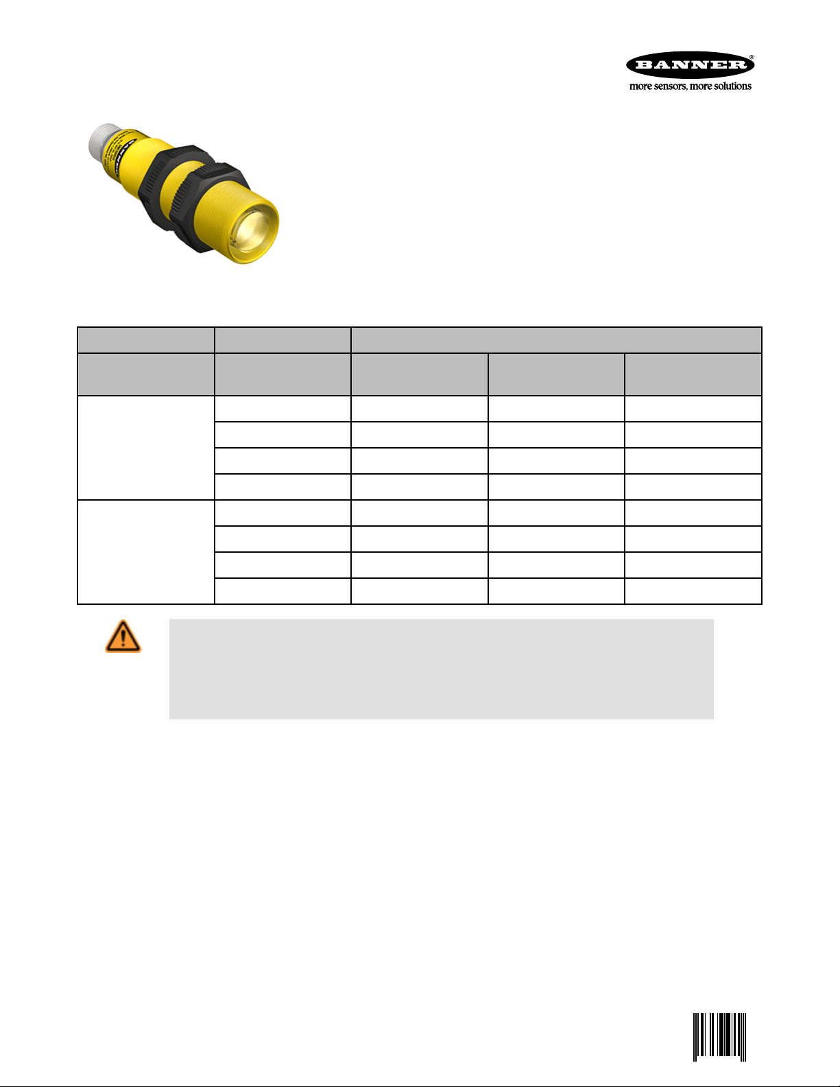
SMI30 Series Intrinsically Safe Sensors
0 035331 3
Rugged, NEMA 6P-plus sensors in 30 mm threaded PBT barrel housings
• Designed for use with approved amplifiers and intrinsically safe barriers in explosive
environments
• Very high excess gain; 350 foot range (standard 10 ms models)
• Fast 1 ms response models (152 foot range) available by special order
• Totally sealed, self-contained, intrinsically safe threaded-barrel opposed mode sensor
pairs in rugged 30 mm PBT housings
• Highly immune to noise: the best noise immunity of any self-contained emitter/receiver
pair
• Internal alignment indicator LED may be viewed either from the side or from the front
of the receiver through the lens
• Integral mini-type 3-pin "QD" (quick-disconnect) connector
Models
Response Time
Models with 10 ms response time
Models with 1 ms response time
WARNING: Not To Be Used for Personnel Protection
Never use this device as a sensing device for personnel protection. Doing so could lead to serious
injury or death. This device does NOT include the self-checking redundant circuitry necessary to allow its
use in personnel safety applications. A sensor failure or malfunction can cause either an energized or deenergized sensor output condition.
Frequency "A" (standard)
Repeatability: 1 ms Repeatability: 1.6 ms Repeatability: 2.3 ms
Emitters SMI306EQ SMI306EBQ SMI306ECQ
Receivers (light operate) SMI30AN6RQ SMI30AN6RBQ SMI30AN6RCQ
Receivers (dark operate) SMI30RN6RQ SMI30RN6RBQ SMI30RN6RCQ
Repeatability: 360 µs Repeatability: 210 µs
Emitters SMI306EYQ SMI306EYCQ
Receivers (light operate) SMI30AN6RYQ SMI30AN6RYCQ
Receivers (dark operate) SMI30RN6RYQ SMI30RN6RYCQ
Frequency "B" (special
order)
Frequency "C" (special
order)
Overview
Banner SMI30 Series intrinsically safe barrel sensors are extremely rugged and powerful opposed mode infrared sensor pairs designed
for the most demanding industrial applications. Their high excess gain (350 foot range) provides enough sensing power to penetrate the
heaviest contamination (see Excess Gain Curve). Electronics are fully epoxy-encapsulated for maximum resistance to mechanical shock
and vibration. Positive sealing at both ends, with no exposed epoxy interfaces, eliminates all leak paths (including capillary leakage).
Construction exceeds NEMA 6P (IEC IP 67) standards. Sensors are approximately 1.2 inches in diameter by 4 inches long.
SMI30 series dc receivers operate from 10 to 30V dc. These sensors carry entity approval from Factory Mutual Research and CSA for
intrinsically safe operation in hazardous atmospheres. SMI30 Series sensors are certified as being intrinsically safe when used with approved intrinsic safety barriers. SMI30 Series sensors are suitable for intrinsically safe use in hazardous locations as defined by Article
500 of the National Electrical Code (see classifications, above right). SMI30 Series sensors are also certified by Factory Mutual and CSA
as non-incendive devices when used in Division 2 locations (except Groups E and F) without intrinsic safety barriers.
SMI30 Series sensors may be wired for either two- or three-wire current-sinking operation. In the three-wire hookup, which requires two
intrinsic-safety barriers (or one dual barrier), the sink current is 15 mA. The two-wire hookup, which requires one barrier, sinks ≤ 10 mA
(OFF state) and ≥ 20 mA (ON state).
P/N 035331 Rev. E 4/4/2013
Page 2

SMI30 Series Intrinsically Safe Sensors
Intrinsic safety barriers are available from Banner. Current trip point amplifier CI3RC2 is also offered. Several mounting brackets are
available.
SMI30 Series receivers have a red LED alignment indicator that lights whenever the receiver "sees" its modulated light source. Emitters
have a red LED to indicate "power on". All LED indicators are mounted internally to preserve the waterproof integrity of the sensor housing, and are visible from both the side and front of the sensor through the sensor's quad-ring sealed acrylic lens.
The innovative circuitry used in SMI30 Series emitters and receivers provides the best noise immunity of any self-contained opposed
mode sensor pair. For applications where optical crosstalk between sensors might be a problem, SMI30 Series emitters and receivers
are available with a choice of three modulation frequencies (frequency "A", frequency "B", or frequency "C"). This makes it possible to
use high-powered sensor pairs of different frequencies in close proximity to each other without crosstalk. (NOTE: frequency "A" is standard; frequencies "B" and "C" are available by special order. An emitter and its receiver must be of the same modulation frequency.) See
the models table for a summary of models.
Each unit is supplied with two hexagonal jam nuts. A 30 mm clearance hole is required for mounting, and mounting bracket models
SMB30MM, SMB30S, and SMB30C are available. All models have a built-in standard quick-disconnect ("QD") connector. "QD" models
mate with 12-foot long model SMICC-312 or 30-foot long model SMICC-330 mini-type QD cable (sold separately from sensor).
Design Standards
ATEX (European) EN 60079-0, EN 60079-11, EN 60079-26
Canadian CAN/CSA C22.2 No. 0-M91, No. 142-M1987, No.157-92, No. 1010.1, E60079-0, E60079-11
United States FM Class 3600, 3610, and 3810, ANSI/ISA 61010-1 (82.02.01), ANSI/ISA 60079-0, 60079-11, and 60079-26
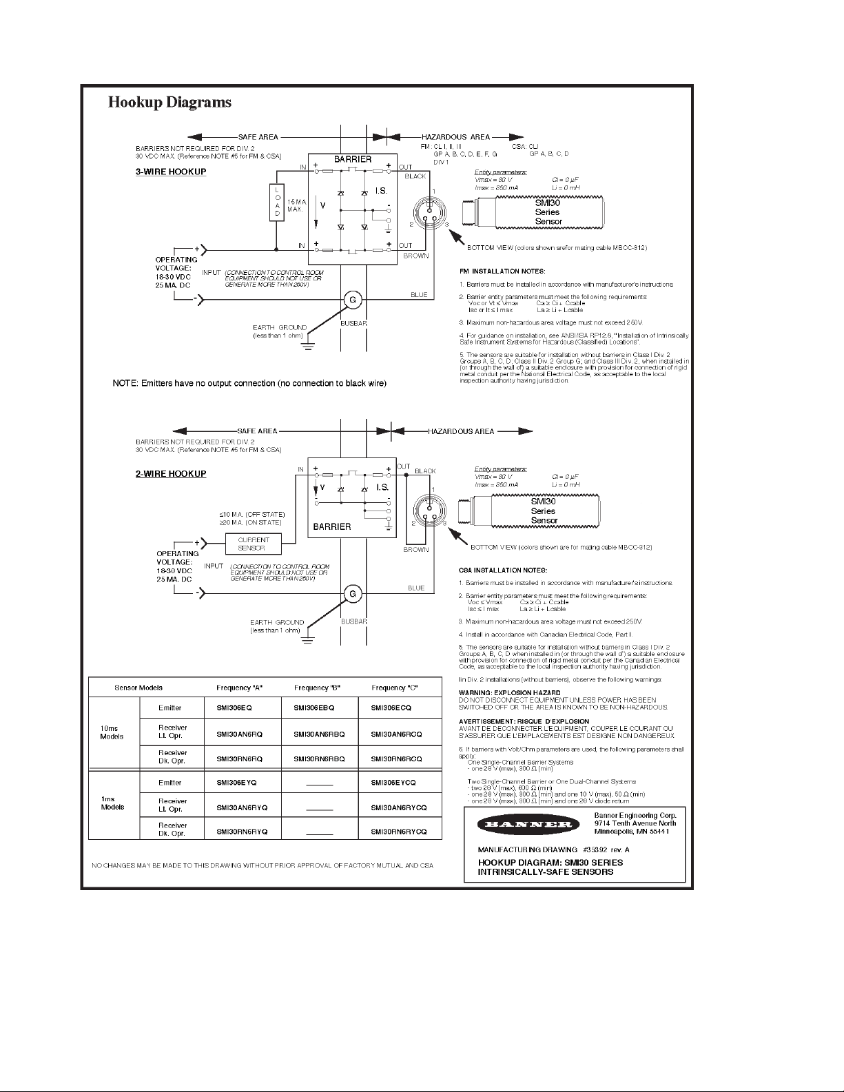
Wiring Information
SMI30 Series sensors are certified intrinsically safe ONLY when used with certified energy-limiting intrinsically safe barriers. Emitter units
use a two-wire hookup (there is no output connection). Note from the wiring/hookup diagram that the receiver installation may be made
using either a single barrier (2-wire hookup) or with a dual channel barrier (3-wire hookup). In the 2-wire configuration, the sensor acts as
a current sink, drawing less than 10 mA in the OFF state and more than 20 mA in the ON state. The customer must provide a current
sensing device ("current sensor" in the diagram) to convert the current to a logic level. SMI30 Series sensors may be used with Banner
Current Amplifier Control Module CI3RC2.
The CI3RC2 module may be purchased (with model RS-11 module socket, one dual-channel barrier, and DIN rail barrier mounts included) by specifying kit model CI2BK-2. One dual-channel intrinsic barrier (alone) may be ordered by specifying model CI2B-1. See Acces-
sories on page 6.
In the 3-wire configuration, the output may be used directly to control loads of less than 15 mA.
In selecting the barrier, it is important to consider the barrier's resistance. The sensors must have at least 10 volts across the brown and
blue power leads for proper operation, and the barrier will cause a voltage drop due to its resistance. The formula that determines how
much resistance is allowed is: R = 40 (supply voltage – 10 volts).
If the supply voltage is 24V dc, then the maximum resistance is 560 ohms. If the supply voltage is 18V dc, then the maximum resistance
is 320 ohms. This includes the resistance of any current sensing device used (in the 2-wire configuration), so the barrier resistance must
be further reduced by the current sensor resistance.
Note that, in the 3-wire hookup, the barrier is in series with the load. This results in an apparent saturation voltage of the output that is
higher than the sensor output by the amount of IxR (current times voltage) drop through the barrier.
Emitters use the 2-wire hookup; receivers use either 2- or 3-wire hookup. Review to the models table for a summary of models.
Barriers are generally classified as either "positive input" or "negative input". SMI30 Series intrinsically safe sensors require "positive
input" barriers for both supply and load. The blue (negative supply) lead of the sensor is normally connected to the ground terminal of the
barrier.
The user of this equipment is responsible for proper installation and maintenance of the equipment, and must conform with the certification requirements relating to barriers and to maximum allowable capacitance and inductance of the field wiring. If you are in doubt about
these requirements, our applications engineers can refer you to the appropriate authority.
2 www.bannerengineering.com - tel: 763-544-3164 P/N 035331 Rev. E
Page 3
SMI30 Series Intrinsically Safe Sensors
MAXI-AMP CI3RC2 Current Amplifier Module
Banner MAXI-AMP module model CI3RC2 (part number 36606) is a self-contained module that converts the current output signal of an
SMI30 Series sensor to a trip point switch.
Hookup Using Two Single-Channel Barriers
P/N 035331 Rev. E www.bannerengineering.com - tel: 763-544-3164 3
Page 4

3
4 5 6 7 8
2111109
105 to 130V ac
In
I.S.
+ +
– –
I.S. Barrier
Out
CI3RC2
210 to 250V ac
AC
Supply
Relay Output
5 Amp Contacts
Input:
10mA (OFF State)
20mA (ON State)
Aux.
Blue
Brown
32
1
Input
Common
Opto-Coupler
Output: 20mA max.
Earth Ground
(less than 1)
Non-Hazardous Area Hazardous Area
SMI Series
Emitter
G
Busbar
In
I.S.
+ +
– –
I.S. Barrier
Out
Bottom View of Cable
Connector on Sensor
(colors shown are for mating
cable model SMICC-3xx)
Blue
Brown
32
1
SMI Series
Receiver
Black
3
4 5 6 7 8
2111109
105 to 130V ac
In
+ +
+ +
– –
Dual Barrier
I.S.
In
Out
Out
CI3RC2
210 to 250V ac
AC
Supply
Relay Output
5 Amp Contacts
Bottom View of Cable
Connector on Sensor
(colors shown are for mating
cable model SMICC-3xx)
Input:
10mA (OFF State)
20mA (ON State)
Aux.
Blue
Blue
Brown
Brown
Black
32
1
1
32
Input
Common
Opto-Coupler
Output: 20mA max.
Earth Ground
(less than 1)
Non-Hazardous Area Hazardous Area
SMI Series
Emitter
SMI Series
Receiver
G
Busbar
SMI30 Series Intrinsically Safe Sensors
Hookup Using One Dual-Channel Barrier
Both sensors of the opposed mode pair are wired to model CI3RC2 using the two-wire hookup, which requires the use of two single channel
or one dual channel intrinsic safety barrier(s). In this mode, the SMI30
receiver sinks less than or equal to 10 milliamps in the "OFF" state and
greater than or equal to 20 milliamps in the "ON" state. The CI3RC2
senses this current change and switches internal relays that are easily
wired to most loads and/or additional control circuitry.
Model CI3RC2 is powered by either 105 to 130 or 210 to 250V ac. The
CI3RC2 supplies power to operate both the emitter and receiver.
Inputs are protected against short circuits. Built-in circuit diagnostics indicate an overload of either input by pulsing an LED status light.
The CI3RC2 module has two isolated output switches. There is a 5
amp rated SPDT electromechanical relay, and a solid-state transistor
switch which may be used for logic-level interfaces.
For more information, refer to the datasheet packed with the CI3RC2.
CI3RC2 Specifications
General Output Configuration
Supply Voltage
105 to 130 or 210 to 250V ac, 50/60 Hz (8VA)
Indicator LEDs
4 www.bannerengineering.com - tel: 763-544-3164 P/N 035331 Rev. E
SPDT Electromechanical Relay
Contact rating: 250V ac max., 24V dc max., 5 amps
max. (resistive load), 1/10 HP at 240V ac. Install transi-
Page 5

SMI30 Series Intrinsically Safe Sensors
General Output Configuration
Status indicator for OUTPUT "ON" and INPUT overload/short.
Operating Temperature
0 to 50 °C (32 to 122 °F)
Inputs
Trip point for output "OFF": ≤ 10 milliamps
Trip point for output "ON": ≥ 20 milliamps
Trip point range for input overload indication: 30mA ≤ I
≤ 80mA
Construction
Rugged NORYL® polyphenylene oxide (PPO™)
housing, 1.6" x 2.3" x 4". Standard round-pin 11-pole
base. Use RS-11 socket or equivalent.
SMI30 Specifications
Supply Voltage
Emitters: 10 to 30V dc at 25 mA
Receivers: 10 to 30V dc at 15 mA max. Division 1 use,
with barriers, requires minimum system supply voltage
of 10V. See Wiring Information on page 2.
Sensing Beam
880 nanometers, infrared; effective beam size 0.75
inch diameter.
Indicator
Internal red LED lights whenever the receiver sees its
modulated light source. Emitters have red "power on"
indicator LED. All indicators are visible through the lens
or from side of the sensor.
Construction
NEMA 6P, IEC IP67.
30 mm diameter tubular threaded PBT housing, posi-
tive sealing at both ends; quad-ring sealed acrylic lens.
Electronics are fully epoxy encapsulated. Two PBT jam
nuts are provided.
Mounting Alternatives
30 mm clearance hole
SMB30C split clamp mounting bracket; SMB30MM
two-axis mounting bracket; SMB30S swivel mounting
bracket. See Accessories on page 6
ent suppressor (MOV) across contacts that switch inductive loads.
Closure time: 10 milliseconds max.
Release time: 10 milliseconds max.
Maximum switching speed: 20 operations/second
Mechanical life: 20,000,000 operations
Solid-State DC Relay
SPST optically-coupled transistor
30V dc max., 20mA max
Output
Receivers only: Current sinking NPN open-collector
transistor. Three-wire hookup sinks 15 mA maximum
continuous, 10-30V dc. Two-wire hookup sinks ≤10 mA
(OFF state) and ≥20 mA (ON state), 10-30V dc. Outputs are short-circuit protected.
Response Time
10 milliseconds on/off (models with 1 ms response are
available by special order)
Repeatability
See excess gain curve. Response Time and Repeatability specifications are independent of signal strength.
Operating Temperature
–40 to +70 °C (–40 to +18 °F).
Cable
Three-wire mini-type QD cable (12 ft. long model
SMICC-312 or 30 ft. long model SMICC-330).
Cable electrical properties: 40 pf/ft.; 0.20 μH/ft.
Order cable separately from sensor.
Certifications
ATEX (European)
II 2 G Ex ib IIC T5 Ta = -40°C to 70°C - 35331; Entity FM12ATEX094X
Entity Parameters: V
= 30 V, I
Max
= 350 mA, Ci = 0, Li = 0.
Max
I / 1 / Ex ib / IIC / T5 Ta = 70°C - 35331; Entity
Non-incendive for Class I, Division 2, Groups A, B, C and D, T5 Ta = -40°C to 70°C
Canada
Entity Parameters: V
= 30 V, I
Max
= 350 mA, Ci =0.3 μF, Li = 0 mH.
Max
a = 6EQ, 6EBQ, 6ECQ, 6EYCQ, AN6RQ, AN6RBQ, AN6RCQ, RN6RQ, RN6RBQ, RN6RCQ, 6EYQ,
N6RYQ, AN6RYCQ, RN6RYQ, RN6RYCQ.
P/N 035331 Rev. E www.bannerengineering.com - tel: 763-544-3164 5
Page 6

LR41887
NRTL/C Exia
INTRINSICALLY SAFE/
SECURITE INTRINSEQUE
Jam Nuts
(2 Provided)
Alignment
Indicator (Receivers)
M30 x 1.5
Thread
157.48 mm
(6.2")
PVC-covered
mini-type QD cable
(25 mm (1”) radius
mininum bend)
150 m
(500')
120 m
(400')
90 m
(300')
60 m
(200')
30 m
(100')
0
0
500 mm
1000 mm
1500 mm
500 mm
1000 mm
1500 mm
0
20"
40"
60"
20"
40"
60"
DISTANCE
SMI30 Series
Opposed Mode
10 ms Response
75 m
(250')
60 m
(200')
45 m
(150')
30 m
(100')
15 m
(50')
0
0
500 mm
1000 mm
1500 mm
500 mm
1000 mm
1500 mm
0
20.0"
40.0"
60.0"
20.0"
40.0"
60.0"
DISTANCE
SMI30 Series
Opposed Mode
1 ms Response
1
10
100
1 m
(3.3')
10 m
(33')
100 m
(330')
1000 m
(3300')
0.1 m
(0.33')
1000
10000
100000
E
X
C
E
S
S
G
A
I
N
DISTANCE
SMI30 Series
Opposed Mode
1 ms Response models
10 ms Response models
Certifications
United States
Dimensions
SMI30 Series Intrinsically Safe Sensors
Intrinsically safe for Class I, Zone 1 AEx ib Group IIC T5 Ta = -40°C to 70°C - 35331; Entity
Non-incendive for Class I, Division 2, Groups A, B, C and D, T5 Ta = -40°C to 70°C
Entity Parameters: V
= 30 V, I
Max
= 350 mA, Ci =0, Li = 0.
Max
a = 6EQ, 6EBQ, 6ECQ, 6EYCQ, AN6RQ, AN6RBQ, AN6RCQ, RN6RQ, RN6RBQ, RN6RCQ, 6EYQ,
N6RYQ, AN6RYCQ, RN6RYQ, RN6RYCQ.
FM12ATEXD094X
Performance Curves
Beam Pattern (10 ms Response Time) Beam Pattern (1 ms Response Time) Excess Gain Curve
Accessories
APG30S Aperture Kit
These new water-tight apertures for SM30 Series sensors may be used to size and shape the effective beam or to limit excess gain for
avoiding "burn-through" effects. Apertures are sold as a kit, which includes a thread-on stainless steel housing, a flat glass lens, two
quad-ring seals, and 3 round and 3 slotted aperture disks.
6 www.bannerengineering.com - tel: 763-544-3164 P/N 035331 Rev. E
Page 7

66
56
13
A
B
70
57
A
B
C
57
SMI30 Series Intrinsically Safe Sensors
The stainless steel aperture housing functions equally well with VALOX® and stainless steel sensor models. The glass lens is useful for
protecting the SM30's acrylic lens against substances that are hostile to acrylics, such as concentrated acids and alkalis and industrial
solvents.
Aperture sizes include the following:
• Round: .06", .12", and .70" diameter
• Slotted: .04", .10", and .20" wide
APG30S
Kit includes round apertures of 0.05 in, 0.12", and 0.70" diameter; slotted widths of 0.04",
0.10" and 0.20".
Used with SM30 and SMI30 models.
Intrinsic Safety Kits for use with Intrinsic Safe Sensors
Kit CI2BK-1 (36860) includes a CI3RC2 current amplifier, one RS- 11 socket, one DIN-rail mount, and one single-channel intrinsically
safe barrier.
Kit CI2BK-2 (36605) includes a CI3RC2 current amplifier, one RS- 11 socket, one DIN-rail mount, and one dual-channel intrinsically safe
barrier.
Barriers are available separately:
• Single channel barrier (model CIB-1, p/n 27030)
• Dual channel barrier (model CI2B-1, p/n 36865)
Mounting Brackets
SMB30C
• 30 mm split clamp, black
PBT bracket
• Stainless steel mounting
hardware included
• Mounting hole for 30 mm
sensor
SMB30MM
• 12-ga. stainless steel
bracket with curved
mounting slots for versatile
orientation
• Clearance for M6 (¼ in)
hardware
• Mounting hole for 30 mm
Hole center spacing: A=ø 45
sensor
Hole size: B=ø 27.2
Hole center spacing: A = 51, A to B = 25.4
Hole size: A = 42.6 x 7, B = ø 6.4, C = ø 30.1
SMB30S
• Swivel bracket with 30 mm
mounting hole for sensor
Special Conditions for Safe Use. Parts of the enclosure are nonconducting and may generate an ignition-capable level of ESD.
Clean the equipment with a damp cloth only.
• Adjustable captive swivel
ball
• Black reinforced thermoplastic polyester
• Stainless steel mounting
and swivel locking hardware included
P/N 035331 Rev. E www.bannerengineering.com - tel: 763-544-3164 7
Page 8

52 Typ.
7/8-16UN-2B
ø 25.5
2
3
1
SMI30 Series Intrinsically Safe Sensors
Hole center spacing: A=ø ##.#
Hole size: A=ø #.#, B=ø ##.#
Cables
3-Pin Mini-Style Cordsets for Intrinsically Safe Sensors
Model Length Style Dimensions (mm) Pinout (Female)
SMICC-306 1.83 m Threaded,
SMICC-312 3.66 m
straight
SMICC-330 9.14 m
1 = Black
2 = Brown
3 = Blue
Banner Engineering Corp Limited Warranty
Banner Engineering Corp. warrants its products to be free from defects in material and workmanship for one year following the date of
shipment. Banner Engineering Corp. will repair or replace, free of charge, any product of its manufacture which, at the time it is returned
to the factory, is found to have been defective during the warranty period. This warranty does not cover damage or liability for misuse,
abuse, or the improper application or installation of the Banner product.
THIS LIMITED WARRANTY IS EXCLUSIVE AND IN LIEU OF ALL OTHER WARRANTIES WHETHER EXPRESS OR IMPLIED (INCLUDING, WITHOUT LIMITATION, ANY WARRANTY OF MERCHANTABILITY OR FITNESS FOR A PARTICULAR PURPOSE), AND
WHETHER ARISING UNDER COURSE OF PERFORMANCE, COURSE OF DEALING OR TRADE USAGE.
This Warranty is exclusive and limited to repair or, at the discretion of Banner Engineering Corp., replacement. IN NO EVENT SHALL
BANNER ENGINEERING CORP. BE LIABLE TO BUYER OR ANY OTHER PERSON OR ENTITY FOR ANY EXTRA COSTS, EXPENSES, LOSSES, LOSS OF PROFITS, OR ANY INCIDENTAL, CONSEQUENTIAL OR SPECIAL DAMAGES RESULTING FROM ANY
PRODUCT DEFECT OR FROM THE USE OR INABILITY TO USE THE PRODUCT, WHETHER ARISING IN CONTRACT OR WARRANTY, STATUTE, TORT, STRICT LIABILITY, NEGLIGENCE, OR OTHERWISE.
Banner Engineering Corp. reserves the right to change, modify or improve the design of the product without assuming any obligations or
liabilities relating to any product previously manufactured by Banner Engineering Corp.
www.bannerengineering.com - tel: 763-544-3164
 Loading...