

Page 1
SL Series Slot Sensor
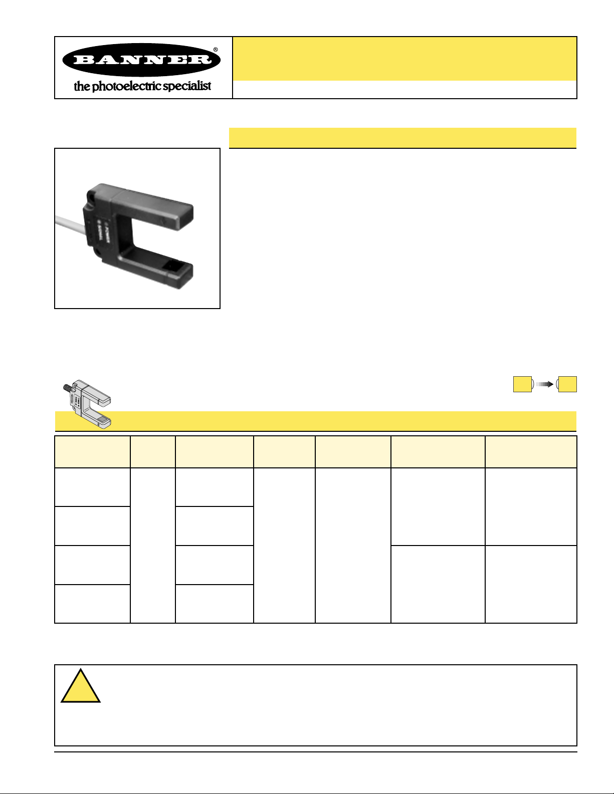
SL0 Series Slot Sensor
Self-contained opposed-mode sensor pair
Printed in USA P/N 60073
SL0 Series Slot Sensor Features
• An easy-to-use self-contained opposed-mode sensor pair in a rugged U-shaped housing
• Easy and economical to mount
• Molded-in beam guides simplify mounting and beam placement
• 30 mm slot width for a wide variety of sensing applications
• Applications include hole detection, gear tooth detection, edge guiding and counting
of opaque materials
• 10 to 30V dc operation
• Bipolar PNP/NPN outputs
• Choose 1 millisecond or 300 microsecond response
• 2 mm effective beam
• Dark or light operate
• Choose integral, unterminated cable or QD models
Models
Slot
Width Cable*
Supply
Voltage
Output
Type Response Repeatability
SL030VB6
SL0 Series Slot Sensor Models
Infrared, 890 nm
1 millisecond 250 microseconds
30 mm
(1.2")
2 m (6.5')
5-wire cable
10-30V dc
Bipolar
NPN (sinking)
and
PNP (sourcing)
5-Pin
Euro-style QD
SL030VB6Q
2 m (6.5')
5-wire cable
5-Pin
Euro-style QD
SL030VB6YQ
SL030VB6Y
300 microseconds 75 microseconds
*NOTES: 1) 9 m (30') cables are available by adding suffix “W/30” to the model number of the cabled version (e.g., SL030VB6 W/30).
2) A model with a QD connector requires an accessory mating cable. See page 4.
WARNING . . .
Not To Be Used for Personnel Protection
Never use these products as sensing devices for personnel protection. Doing so could lead to serious injury or death.
These sensors do NOT include the self-checking redundant circuitry necessary to allow their use in personnel safety applications.
A sensor failure or malfunction can cause either an energized or de-energized sensor output condition. Consult your current Banner Safety
Products catalog for safety products which meet OSHA, ANSI and IEC standards for personnel protection.
!
Page 2
SL0 Series Slot Sensor
page 2
Banner Engineering Corp. • Minneapolis, U.S.A.
Website: http://www.baneng.com • Tel: 888.373.6767
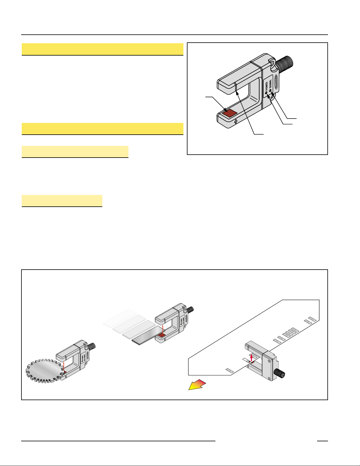
Figure 2. SL0 Series typical applications
Gear Tooth Detection Edge Detection
Code Reading
(Holes in Opaque Materials)
SL0 Series Slot Sensor Overview
The SL0 Series Slot Sensor (sometimes called a “Fork Sensor”) comprises an opposed-mode emitter and its receiver inside a single convenient housing. Opposed-mode sensing is very reliable, and the single self-contained housing provides easy installation, with no sensor
alignment required. In addition, the molded-in arrow on the emitter
portion of the housing and the slotted design on the receiver portion
of the housing show at a glance the position of the beam, simplifying
installation placement.
Using the SL0 Series Slot Sensor
Light/Dark Operate Select
Selecting Light or Dark Operate is a simple procedure: connect the
gray wire (see hookups, page 3), to +V (10-30V dc) for Dark Operate, and to dc common (or open) for Light Operate.
LED Indicators
The Slot Sensor features two LED Indicators: Power (green) and Signal (yellow). They
indicate the following:
Green ON steady: Power ON
Yellow ON steady: Sensor sees light
Yellow flashing: Excess gain is marginal (1 to 1.5x) in light condition
Figure 1. SL0 Series features
Emitter
Signal LED
Power ON LED
Receiver (Beam Aligns at Groove)
Page 3

SL0 Series Slot Sensor
page 3
Banner Engineering Corp. • Minneapolis, U.S.A.
Website: http://www.baneng.com • Tel: 888.373.6767
Figure 3. SL0 Series Slot Sensor dimensions
10.0 mm
SL0 Series Slot Sensor Specifications
Slot Opening 30 mm (1.2") wide x 45 mm (1.8") deep overall; beam set in 10 mm (0.4") from outer edge
Supply Protection Circuitry Protected against reverse polarity and transient voltages
Output Configuration Bipolar: NPN (current sinking) and PNP (current sourcing)
Output Rating 150mA, each output
Output Protection Circuitry Protected against false pulse on power-up and short-circuit of outputs
Output Response Time 1 millisecond or 300 microseconds, depending on model
Repeatability 250 microseconds or 75 microseconds, depending on model
Adjustments None
Indicators Green: Power ON/OFF indicator
Yellow: Signal Condition indicator
Construction Housing: ABS/polycarbonate
Lenses: Acrylic
Environmental Rating IP67, NEMA 6
Connections 2 m (6.5') or 9 m (30') 5-conductor PVC-jacketed attached cable or 5-pin Euro-style quick-disconnect
(QD) connector. QD cables are ordered separately; see page 4.
Operating Conditions Operating Temperature: -40° to +70°C (-40° to +158°F)
Maximum relative humidity: 90% @ 50°C (non-condensing)
Supply Voltage and Current 10 to 30V dc, 30 mA
SL0 Series Slot Sensor Hookups
Cabled models
Quick-Disconnect models
*For Dark Operate, connect gray wire
to + (brown).
For Light Operate, connect gray wire
to – (blue) or leave circuit open.
Power LED
(Green)
Signal LED
(Yellow)
(0.39)
30.2 mm
(1.19")
10.9 mm
(0.43")
45.0 mm
(1.77")
72.0 mm
(2.84")
6.0 mm
(0.24")
2x ø5.6 mm
(0.22")
18.8 mm
(0.74")
M12 x 1
6.0 mm
(0.24")
40.0 mm
52.0 mm
(2.05")
(1.58")
20.2 mm (0.80")
bn
bu
wh
bk
gy
Load
Load
+
–
(See right*)
10 - 30V dc
bn
bu
wh
bk
gy
Load
Load
(See left*)
+
10 - 30V dc
–
Page 4

SL0 Series Slot Sensor
WARRANTY: Banner Engineering Corp. warrants its products to be free from defects for one year. Banner Engineering Corp. will repair or
replace, free of charge, any product of its manufacture found to be defective at the time it is returned to the factory during the warranty period. This warranty does not cover damage or liability for the improper application of Banner products. This warranty is in lieu of any other warranty either expressed or implied.
Banner Engineering Corp., 9714 Tenth Ave. No., Minneapolis, MN 55441 • Phone: 888.373.6767 • http://www.baneng.com • E-mail: sensors@baneng.com
Accessories
Quick-Disconnect Cables
The following cables are available for SL0 Series Slot Sensor QD models
Style Model Length Dimensions
5-pin
Euro-style
straight
MQDC1-506
MQDC1-515
MQDC1-530
2 m (6.5')
5 m (15')
9 m (30')
Pin-out
5-pin
Euro-style
right-angle
MQDC1-506RA
MQDC1-515RA
MQDC1-530RA
2 m (6.5')
5 m (15')
9 m (30')
Mounting Brackets
SMBSL
• Angled bracket
• 304 stainless steel
44 mm max.
(1.7")
38 mm max.
(1.5")
M12 x 1
ø 15 mm
(0.6")
12x R2.5mm
(0.10")
8.9 mm
(0.35")
6x ø5.5mm
(0.22")
ø 15 mm
(0.6")
M12 x 1
38 mm max.
(1.5")
Brown Wire
Black Wire
White Wire
Blue Wire
Gray Wire
30.4 mm
(1.20")
10.9 mm
(0.43")
7.6 mm
(0.30")
21.6 mm
(0.85")
41.3 mm
(1.62")
39.9 mm
(1.58")
19.1 mm
(0.75")
51.9 mm
(2.05")
6.0 mm
(0.24")
30.1 mm
(1.19")
10.9 mm
(0.43")
6.4 mm
(0.25")
40.0 mm
(1.58")
10.2 mm
(0.40")
6.0 mm
(0.24")
 Loading...