

Page 1
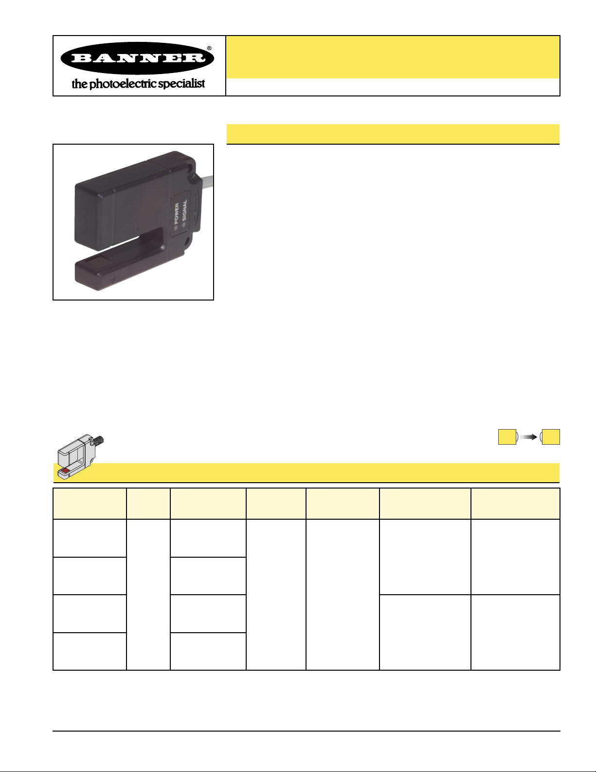
SLE10 Expert™Series Teach-Mode Slot Sensor
Self-contained opposed-mode sensor pair with Teach Mode
Printed in USA P/N 60378
SLE10 Expert Series Slot Sensor Features
• An easy-to-use, self-contained opposed-mode sensor pair in a rugged U-shaped
housing
• Easy push-button programming automatically adjusts sensitivity to optimal setting
• Dynamic TEACH programming option provides on-the-fly convenience and
minimizes the effects of web flutter
• Separate TEACH input allows remote programming by an external device, such as
a switch or a process controller
• Easy output programming eliminates the need for Light or Dark Operate selection
• Choose fast 500 microsecond or 150 microsecond output response
• 1 mm effective beam
• Visible red beam
• Molded-in beam guides simplify mounting and beam placement
• 10 mm slot width for a wide variety of sensing applications
• Applications include label detection, hole detection, edge guiding and counting,
small parts detection
• 10 to 30V dc operation
• Bipolar PNP/NPN outputs
• Choose integral, unterminated cable or QD models
Models
Slot
Width Cable*
Supply
Voltage
Output
Type Response Repeatability
SLE10B6V
SLE10 Expert Series Slot Sensor Models
Visible red, 680 nm
500 microseconds 100 microseconds
10.0 mm
(0.39")
2 m (6.5')
5-wire cable
10-30V dc
Bipolar
NPN (sinking)
and
PNP (sourcing)
5-Pin
Euro-style QD
SLE10B6VQ
2 m (6.5')
5-wire cable
5-Pin
Euro-style QD
SLE10B6VYQ
SLE10B6VY
150 microseconds 75 microseconds
*NOTES: 1) 9 m (30') cables are available by adding suffix “W/30” to the model number of the cabled version (e.g., SLE10B6V W/30).
2) A model with a QD connector requires an accessory mating cable. See page 5.
Page 2

SLE10 Expert™Series Slot Sensor
2
Banner Engineering Corp. • Minneapolis, U.S.A.
Website: http://www.baneng.com • Tel: 888.373.6767
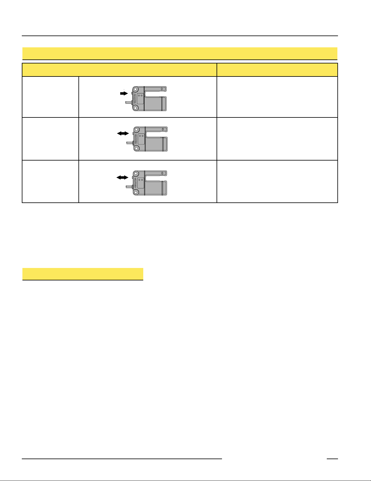
Figure 2. SLE10 Expert Series typical applications
Figure 1. SLE10 Expert Series features
SLE10 Expert Series Slot Sensor Overview
The SLE10 Series Slot Sensor (sometimes called a “Fork Sensor”)
comprises an opposed-mode emitter and its receiver inside a single
convenient housing. Opposed-mode sensing is very reliable, and the
single self-contained housing provides easy installation, with no
sensor alignment required. In addition, the molded-in arrow on the
emitter portion of the housing and the slotted design on the receiver
portion of the housing show at a glance the position of the beam,
simplifying installation placement.
Expert series sensors feature easy-to-use push-button programming,
performed in TEACH mode. TEACH-mode programming may be
performed using either the push button, or remotely, using a remote
switch or process controller. The programming determines whether
the sensor outputs will conduct in light or dark conditions, and defines
the light and dark conditions for the sensor in each application. The
remote switch also may be used to disable the programming push
button for security.
The Dynamic TEACH option provides a means for teaching a series of
conditions; the SLE10 monitors the sensing events and automatically
sets the threshold between light and dark conditions.
Register Mark Detection
on Clear Film
Label Detection
Emitter
Signal LED
Power ON LED
Receiver (Beam Aligns at Groove)
TEACH
Pushbutton
Packaging Film
Register Marks
Page 3
SLE10 Expert™Series Slot Sensor
3
Banner Engineering Corp. • Minneapolis, U.S.A.
Website: http://www.baneng.com • Tel: 888.373.6767
Using the SLE10 Expert Series Slot Sensor
RUN Mode
Normal operation of the SLE10 Expert is called RUN mode. The two LED indicators
(bi-color Green/Red and Yellow) operate as follows in RUN Mode:
Green (RUN Mode): ON steady whenever power is applied
Flashes as received light level approaches the switching threshold
(stability indicator. The stability indicator signals when
maintenance or reprogramming is needed during RUN mode.)
Yellow (Output): ON when the outputs are energized (conducting)
OFF when the outputs are de-energized (not conducting)
If contrast is marginal, the bi-color indicator will flash green (to indicate instability).
Reprogramming the sensor, or cleaning the sensor lenses may solve a problem with
stability.
TEACH Mode
Programming of the SLE10 Expert – setting the sensitivity and selecting output ON and
OFF conditions – is performed in TEACH Mode. The SLE10 provides two methods for
programming: Static TEACH and Dynamic TEACH. Static TEACH is used in all
programming situations to set up the sensor’s output ON and output OFF conditions.
Sensitivity is then set using either the Static method described below or the Dynamic
method on page 4.
Both Static TEACH and Dynamic TEACH may be performed using either the sensor’s
TEACH push button or the Remote TEACH line (see page 6).
Static TEACH
Determining the Output ON and OFF Conditions
The two sensing conditions may be presented in either order. The condition presented
first is the condition for which the outputs will energize (the “Output ON” target).
Setting Sensitivity
Sensitivity is automatically set (and optimized) when teaching the sensor the ON and
OFF conditions. When the push button is clicked, the sensor samples each sensing
condition and registers it into memory. After the second sensing condition is
registered, the SLE10 Expert automatically sets the sensitivity to the optimum value
for the application, and then returns to RUN mode.
The two LED indicators (bi-color Green/Red and Yellow) operate as follows in
TEACH Mode:
Red (TEACH Mode): Lights when the sensor “sees” its modulated light source;
pulse rate is proportional to the received light signal strength
during TEACH programming
Yellow (Output): ON to indicate TEACH output ON condition
OFF to indicate TEACH output OFF condition
The Signal Strength indicator is Banner’s exclusive AID™(Alignment Indicating
Device). Its pulse rate increases as the received light signal strength increases (during
programming). This feature simplifies accurate alignment during TEACH mode, and
gives a relative indication of sensing contrast between the light and dark conditions.
Page 4
SLE10 Expert™Series Slot Sensor
4
Banner Engineering Corp. • Minneapolis, U.S.A.
Website: http://www.baneng.com • Tel: 888.373.6767
A Note About the “Clicks”: Clicks are meant to be pressed firmly, then quickly
released. Indicators go ON or OFF after a brief delay; do not wait until LEDs change
status before releasing push button. (If push button is pressed for 2 seconds or
longer, sensor will automatically return to RUN mode.)
Dynamic TEACH
Dynamic TEACH is a method of setting the sensor’s sensitivity while the object to be
sensed is in motion. Typical applications are label sensing and small parts detection. In
a label application, web flutter may change the amount of light passing through the
label and its backing material. Dynamic TEACH will sense this variation and adjust the
sensitivity to account for it.
In a small parts detection application, alignment of the object to the sensor’s effective
beam may make Static TEACH difficult. In this case, Dynamic TEACH will allow you to
pass individual or multiple parts through the beam; the sensor then will detect them and
set the sensitivity automatically.
Determining the Output ON and OFF Conditions
Dynamic TEACH is used for optimizing the sensor’s sensitivity and will not configure the
output ON and OFF conditions. A Static TEACH must be used first to change the output
ON and OFF conditions, if needed. If the outputs are configured properly for your
installation, Dynamic TEACH may be performed as needed without reverting back to
Static TEACH.
Setting Sensitivity
Sensitivity is automatically set and optimized when the sensor is taught dynamically.
When the push button is depressed and held, the sensor continues to sample events
and registers them into memory. Upon release of the button, the sensor chooses the
optimum setting for the application and then returns to RUN mode.
Push Button Resulting Indicator Status
TEACH Condition #1
(Output ON state)
Present the first
sensing condition to
the sensor and singleclick.
†
Press and hold until
the bi-color (green/red)
indicator begins to
flash red, or turns OFF.
Yellow: ON
Red: Pulses to indicate relative received signal
strength.
Yellow: OFF
Red: Pulses to indicate relative received signal
strength.
TEACH Condition #2
(Output OFF state)
Present the second
sensing condition to
the sensor and singleclick.
If contrast is acceptable, the sensor returns to
RUN mode; other wise it will return to TEACH
Condition #1.
Green: ON (or flashes if signal is close to the
switching threshold).
Yellow: OFF, until the sensing condition changes.
†
NOTE: The sensor will return to RUN mode if the first TEACH condition is not registered within 90 seconds. TEACH mode may be cancelled
before either condition #1 or #2 by holding the push button depressed for ≥ 2 seconds.
Static TEACH Sequence
Push and Hold
≥ 2 Seconds
Single-Click
Single-Click
Sensing
Condition #1
(Output ON State)
Sensing
Condition #2
(Output OFF State)
Page 5

SLE10 Expert™Series Slot Sensor
5
Banner Engineering Corp. • Minneapolis, U.S.A.
Website: http://www.baneng.com • Tel: 888.373.6767
Dynamic Sampling Rate
When using Dynamic TEACH to sample an application for programming, it is important
to consider the speed of the object being sensed. The sensor’s sampling rate during this
set-up process is much slower than its response time in RUN mode. Once sampling is
complete and the sensor returns to RUN mode, sensor response time returns to its
original value.
Use the following formula to calculate the target object speed for Dynamic TEACH
sampling:
Max. speed of object =
as it passes the sensor
For example, for an object 0.125" wide: Or for an object 2 mm wide:
(0.125" - 0.04") (2 - 1 mm)
Max. object speed = = 9.4" /second Max. object speed = = 111 mm/second
0.009 seconds 0.009 seconds
*NOTE: The Dynamic Sampling Rate for high-speed models (“Y” model suffix) is
8 milliseconds (0.008 seconds)
†
NOTE: The sensor will return to RUN mode if the first TEACH condition is not registered within 90 seconds. Dynamic TEACH mode may be
cancelled by waiting 90 seconds or by cycling sensor power.
Dynamic TEACH Sequence
Push Button Resulting Indicator Status
Initiates Dynamic
TEACH Mode
Press and hold until
the bi-color (green/red)
indicator begins to
flash red, or turns OFF.
Yellow: ON
Red: Pulses to indicate relative received signal
strength.
Yellow: Pulses at 0.5 Hz.
Red: ON
Ends TEACH Process
If contrast is acceptable, the sensor returns to RUN
mode. Otherwise, it will return to Static TEACH
mode; double-click to initiate Dynamic TEACH.
Green: ON (or flashes if signal is close to the
switching threshold).
Yellow: ON or OFF, depending on condition
Starts TEACH Process
Present the sensing
condition while holding
the button
Yellow: ON Solid
Red: ON Solid
Width of object (in inches) — effective beam (0.04")
Dynamic Sampling Rate (0.009 seconds)*
Sensing
Condition
Push and Hold
≥ 2 Seconds
Double-Click
Push and Hold
≥ 2 Seconds
Release
Page 6

SLE10 Expert™Series Slot Sensor
6
Banner Engineering Corp. • Minneapolis, U.S.A.
Website: http://www.baneng.com • Tel: 888.373.6767
Remote Programming
The gray wire of the SLE10 Expert may be connected to a remote
switch or process controller to disable or enable the push button
(four-pulse) or to program the sensor (single-pulse) through
TEACH mode. Remote programming may be done for both the
Static and Dynamic TEACH procedures.
A remote programming switch is connected between the gray wire
and dc common (see hookup diagrams on page 9). The switch may
be either a normally-open contact, or an open-collector NPN
transistor with its emitter connected to dc common.
Programming is accomplished using a specified sequence of
input pulses. The duration of each pulse is defined as:
0.04 seconds<T<0.8 seconds.
The required spacing between adjacent pulses in a sequence
(a “four-pulse”) is also: 0.04<T<0.8 seconds. The timing diagrams
(Figure 3, right) illustrate the input requirements.
Locking Out (Disabling) the Push Button
When remote programming is used exclusively, it may be beneficial to disable the
push button on the SLE10 Expert to increase the security of the settings. The push
button can be enabled and/or disabled via the remote line only. If the push button is
disabled, TEACH mode cannot be accessed from the push button.
Pulse the Remote TEACH line 4 times (four-pulse) to enable or disable the push
button (see timing diagram, Figure 3).
Static TEACH Programming Using the Remote TEACH Line
To pulse the TEACH line, momentarily connect the remote wire to dc common (no
press-and-hold procedure is required to enter TEACH mode). This is the equivalent of
a “click” when using the sensor TEACH push button.
1. Position the “Output ON” condition and pulse the Remote TEACH line once. The
bi-color (green/red) indicator begins to flash red or turn OFF (the AID
™
function is
indicating signal strength) and the yellow Output indicator will flash briefly and then
go OFF.
2. Position the “Output OFF” condition and pulse the Remote TEACH line again. The
green indicator will turn ON and the sensor will return to RUN mode with the new
settings, if the contrast is adequate. If the contrast is not adequate, the yellow
indicator will turn ON and the red AID indicator will remain active, indicating that
the sensor is waiting for the first TEACH condition to be retaught. (RUN mode
begins a few seconds after the end of TEACH mode.)
NOTE: To exit Static TEACH without updating, hold the Remote TEACH line low
(longer than 2 seconds) until the green indicator goes ON, before teaching the
second target.
Figure 3. Timing programs for remote programming
Single-
Pulse
Input
FourPulse
Input
T
T
0.04 sec
Wait > 0.8 seconds
before next input
T T T
T T T
< T < 0.8 sec
> 0.8 seconds
Wait
before next input
Page 7

SLE10 Expert™Series Slot Sensor
7
Banner Engineering Corp. • Minneapolis, U.S.A.
Website: http://www.baneng.com • Tel: 888.373.6767
Dynamic TEACH Programming Using the Remote TEACH Line
To pulse the TEACH line, momentarily connect the Remote (gray) wire to dc common; no
press-and-hold procedure is required to enter TEACH mode. (This is the equivalent of a
“click” when using the sensor TEACH push button.)
1. Using the Static TEACH procedure, set up the application’s Output ON and OFF
conditions. (This step is not necessary if the Output ON and OFF conditions already
are configured properly for your application.)
2. Double-pulse the Remote TEACH line (see Figure 3). The sensor is now ready for
Dynamic TEACH. The bi-color (green/red) indicator will be ON solid red and the
yellow indicator will flash.
3. Hold the Remote line low. Sample sensing events while continuing to hold the
Remote line low.
4. Release the Remote line when event sampling is complete. The green indicator will
turn ON and the sensor will return to RUN mode with the new settings, if the
contrast is adequate.
If the contrast is not adequate, the red indicator will flash at a rate proportional to the
received light signal strength and the yellow indicator will be ON solid, indicating that the
sensor needs to be retaught. In this case, return to step 2.
NOTE: To exit Dynamic TEACH without updating, wait 90 seconds or cycle sensor power.
Troubleshooting
The SLE10 Expert’s Power LED may begin to alternate flashing red/green; this
indicates a microprocessor memory error. If it occurs, try reteaching the sensor, or
try cycling power ON and OFF, then reteaching the sensor. If this does not solve the
problem, or if it occurs frequently, replace the sensor.
Page 8

SLE10 Expert™Series Slot Sensor
8
Banner Engineering Corp. • Minneapolis, U.S.A.
Website: http://www.baneng.com • Tel: 888.373.6767
SLE10 Expert Series Slot Sensor Specifications
Supply Voltage and Current 10 to 30V dc (10% maximum ripple) at less than 45 mA, exclusive of load
Supply Protection Circuitry Protected against reverse polarity and transient voltages
Output Configuration Bipolar: One current sourcing (PNP) and one current sinking (NPN) open-collector transistor
Output Rating 150mA maximum each output at 25°C, derated to 100 mA at 70°C (derate ≈1 mA per °C)
OFF-state leakage current: less than 5µA @ 30V dc
ON-state saturation current: less than 1V @ 10 mA; less than 1.5V @ 150 mA
Output Protection Circuitry Protected against false pulse on power-up and continuous overload or short-circuit of outputs
Output Response Time Sensors will respond to either a “light” or a “dark” signal of 500 microseconds (or 150 microseconds,
depending on model) or longer duration, 1 kHz max.
NOTE: 1 second delay on power-up; outputs are non-conducting during this time.
Repeatability 100 microseconds or 75 microseconds, depending on model
Adjustments Push-button TEACH mode sensitivity setting (see TEACH mode, page 3); remote TEACH mode input is
provided (gray wire)
Indicators Two LEDs:Yellow and Bi-color Green/Red
Green (RUN Mode): ON when power is applied
Flashes when received light level approaches the switching threshold
Red (TEACH Mode): OFF when no signal is received.
Pulses to indicate signal strength (received light level). Rate is proportional to
signal strength (the stronger the signal, the faster the pulse rate). This is a
function of Banner’s patented Alignment Indicating Device (AID™, USpatent
4356393).
Alternating Red/Green: Microprocessor memory error (see Troubleshooting, page 7)
Flashing
Yellow (Static TEACH): ON to indicate sensor is ready to learn output ON condition
OFF to indicate sensor is ready to learn output OFF condition
Yellow (Dynamic TEACH): Pulses at 0.5 Hz when ready to sample
ON to indicate Dynamic TEACH sampling
OFF to indicate sampling was accepted
Yellow (RUN Mode): ON when outputs are conducting
Construction ABS/polycarbonate housing, acr ylic lenses
Environmental Rating Meets NEMA 6; IEC IP67
Connections PVC-jacketed 5-conductor 2 m (6.5') or 9 m (30') unterminated cable, or 5-pin Euro-style
quick-disconnect (QD) fitting are available. QD cables are ordered separately; see page 10.
Operating Conditions Temperature: -20° to +70°C (-4° to +158°F)
Maximum relative humidity: 90% at 50°C (non-condensing)
Application Notes The first condition presented during TEACH mode becomes the output ON condition.
Effective Beam 1.0 mm (0.04")
Page 9

SLE10 Expert™Series Slot Sensor
9
Banner Engineering Corp. • Minneapolis, U.S.A.
Website: http://www.baneng.com • Tel: 888.373.6767
SLE10 Expert Series Slot Sensor Hookups
SLE10 Expert Series Slot Sensor Dimensions
Cabled Models
Quick-Disconnect Models
10.0 mm
(0.39)
Power LED
(Green)
Signal LED
(Yellow)
10.0 mm
(0.39)
45.0 mm
(1.77")
72.0 mm
(2.84")
6.0 mm
(0.24")
bn
bu
wh
bk
gy
52.0 mm
(2.05")
Load
Load
6.0 mm
(0.24")
40.0 mm
(1.58")
17.5 mm
(0.69")
11.5 mm
(0.45")
2x ø5.6 mm
(0.22")
18.8 mm
(0.74")
+
10 - 30V dc
–
Remote
Teach
M12 x 1
bn
bu
wh
bk
gy
Load
Load
+
10 - 30V dc
–
Remote
Teach
20.2 mm (0.80")
Page 10

SLE10 Expert™Series Slot Sensor
10
Banner Engineering Corp. • Minneapolis, U.S.A.
Website: http://www.baneng.com • Tel: 888.373.6767
Accessories
Quick-Disconnect Cables
The following cables are available for SLE10 Expert Series Slot Sensor QD models
Style Model Length Dimensions
5-pin
Euro-style
straight
MQDC1-506
MQDC1-515
MQDC1-530
2 m (6.5')
5 m (15')
9 m (30')
Pin-out
5-pin
Euro-style
right-angle
MQDC1-506RA
MQDC1-515RA
MQDC1-530RA
2 m (6.5')
5 m (15')
9 m (30')
Mounting Brackets
SMBSL
• Angled bracket
• 304 stainless steel; hardware included
44 mm max.
(1.7")
38 mm max.
M12 x 1
ø 15 mm
(0.6")
12x R2.5mm
(0.10")
8.9 mm
(0.35")
6x ø5.5mm
(0.22")
(1.5")
ø 15 mm
(0.6")
M12 x 1
38 mm max.
(1.5")
Brown Wire
Black Wire
White Wire
Blue Wire
Gray Wire
30.4 mm
(1.20")
10.9 mm
(0.43")
7.6 mm
(0.30")
21.6 mm
(0.85")
41.3 mm
(1.62")
39.9 mm
(1.58")
19.1 mm
(0.75")
51.9 mm
(2.05")
6.0 mm
(0.24")
30.1 mm
(1.19")
10.9 mm
(0.43")
6.4 mm
(0.25")
40.0 mm
(1.58")
10.2 mm
(0.40")
6.0 mm
(0.24")
Page 11

SLE10 Expert™Series Slot Sensor
11
Banner Engineering Corp. • Minneapolis, U.S.A.
Website: http://www.baneng.com • Tel: 888.373.6767
Page 12

SLE10 Expert™Series Slot Sensor
WARRANTY: Banner Engineering Corp. warrants its products to be free from defects for one year. Banner Engineering Corp. will repair or
replace, free of charge, any product of its manufacture found to be defective at the time it is returned to the factory during the warranty
period. This warranty does not cover damage or liability for the improper application of Banner products. This warranty is in lieu of any
other warranty either expressed or implied.
Banner Engineering Corp., 9714 Tenth Ave. No., Minneapolis, MN 55441 • Phone: 888.373.6767 • www.baneng.com • E-mail: sensors@baneng.com
Banner Engineering Corp., 9714 Tenth Ave. No., Minneapolis, MN 55441 • Phone: 888.
 Loading...