

Page 1
®
WARNING . . .
Spare actuators must
NEVER be used to bypass or
otherwise defeat the protective function
of a safety switch. To do so may create
an unsafe situation which could lead to
serious injury or death.
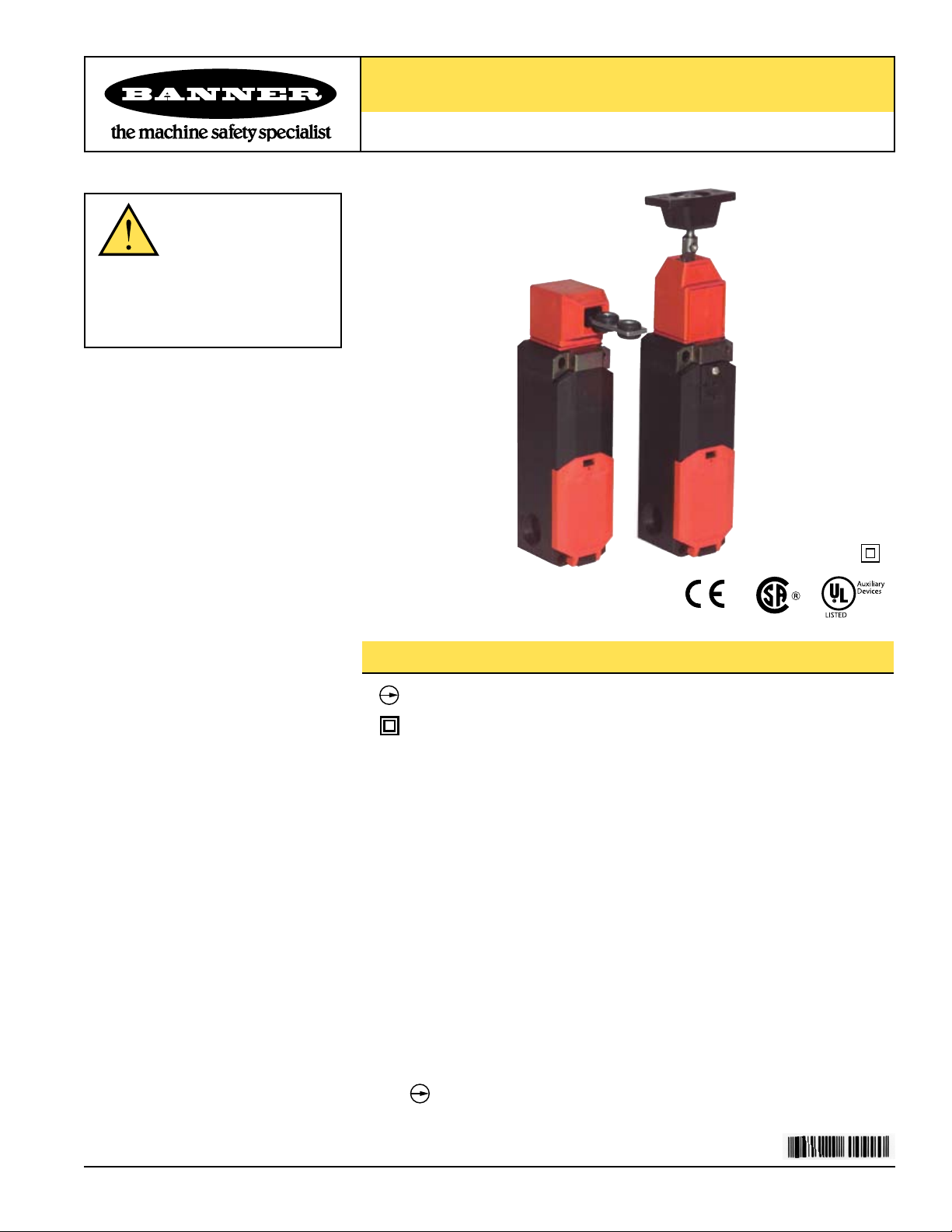
Machine Safety Switches
SI-LS42 Series Locking Style Switch
Features
• Positive opening safety contacts (IEC 60947-5-1) (not dependent upon springs)
•
Insulated device (IEC 60947-5-1)
• Choice of two locking mechanism types:
- Spring lock with energized solenoid release
- Energized solenoid lock with spring unlock
• Two solenoid voltages available:
- 24V ac/dc
- 24 to 48V dc or 24 to 230V ac
• Choose either of two stainless steel actuator types:
- Rigid in-line
- Flexible in-line
• Actuator head rotatable in 90° increments and can be positioned for either horizontal
or vertical actuation
• Choice of four switching contact configurations (with actuator engaged):
- 1 normally-open plus 1 normally-closed
- 2 normally-closed
- 2 normally-closed plus 1 normally-open
- 3 normally-closed
NOTE:
This symbol is used in the switching diagrams to identify the point in
actuator travel where the normally closed safety contact is fully open.
Printed in USA 07/06 P/N 60099 rev. D
Page 2
Machine Safety Switches –
SI-LS42 Series Locking Style Switch
Important Information Regarding the Use of Safety Switches
In the United States, the functions that Banner safety switches are intended to perform are regulated by the Occupational Safety
and Health Administration (OSHA). Whether or not any particular safety switch installation meets all applicable OSHA requirements
depends upon factors that are beyond the control of Banner Engineering Corp. These factors include the details of how the safety
switches are applied, installed, wired, operated, and maintained.
Banner Engineering Corp. has attempted to provide complete application, installation, operation, and maintenance instructions. This
information is found in the instruction manual packaged with each safety switch. In addition, we suggest that any questions regarding
the use or installation of safety switches be directed to the factory applications department at the telephone numbers or address
shown below.
Banner Engineering Corp. recommends that safety switches be applied according to the guidelines set forth in international
(ISO/IEC) standards listed below. Specifically, Banner Engineering Corp. recommends application of these safety switches in a
configuration which meets safety category 4, per ISO 13849 (EN954-1).
In addition, the user of Banner safety switches has the responsibility to ensure that all local, state, and national laws, rules, codes,
and regulations relating to the use of Banner safety switches in any particular application are satisfied. Extreme care is urged that all
legal requirements have been met and that all installations and maintenance instructions are followed.
Application Assistance
Toll Free: 1-888-3-SENSOR (1-888-373-6767)
Email: sensors@bannerengineering.com
Address: 9714 Tenth Avenue North
Minneapolis, MN 55441
U.S. Regulations Applicable to Use of Banner Safety Switches
OSHA Code of Federal Regulations: Title 29, Parts 1900 to 1910
Available from: Superintendent of Documents
Government Printing Office
P.O. Box 371954
Pittsburgh, PA 15250-7954
Tel: 202-512-1800
U.S. Standards Applicable to Use of Banner Safety Switches
ANSI B11 Standards for Construction, Care, and Use of Machine Tools”
Available from: Safety Director
AMT—The Association for Manufacturing Technology
7901 Westpark Drive
McLean, VA 22102
Tel: 703-893-2900
Applicable European and International Standards
ISO/TR 12100-1/-2 “Safety of Machinery
(EN292-1/-2)
ISO 13852 (EN 294) “Safety of Machinery
ISO 13853 (EN 811) “Safety of Machinery
ISO 13849-1 (EN 954-1) “Safety of Machinery
ISO 13855 (EN 999) “Safety of Machinery
ISO 14119 (EN 1088) “Safety of Machinery
IEC/EN 60204-1 “Safety of Machinery
IEC/EN 60947-5-1 “Low Voltage Switchgear
Available from:
15 Inverness Way East
Englewood, CO 80112-5704
Phone: 1-800-854-7179
Fax: 303-397-274
Global Engineering Documents
—Basic Concepts, General Principles for Design”
—Safety Distances to Prevent Danger Zones Being Reached by the Upper Limbs”
—Safety Distances to Prevent Danger Zones Being Reached by the Lower Limbs”
—Safety Related Parts of Control Systems”
—The Positioning of Protective Equipment in Respect to Approach Speeds of Parts of the Human Body”
—Interlocking Devices Associated with Guards—Principles for Design and Selection”
—Electrical Equipment of Machines”
—Electromechanical Control Circuit Devices”
0
2 P/N 60099 rev. D
Banner Engineering Corp. • Minneapolis, MN U.S.A.
www.bannerengineering.com • Tel: 763.544.3164
Page 3
Machine Safety Switches –
0 (0)
7.0 (0.28)
8.0 (0.31)
9.0 (0.35)
41 (1.61)
mm (in)
Engaged
Disengaged
21-22
13-14
Safety
Monitor
0 (0)
41 (1.61)
mm (in)
Engaged
Disengaged
11-12
21-22
Safety
Safety
7.0 (0.28)
9.0 (0.35)
0 (0)
41 (1.61)
mm (in)
Engaged
Disengaged
31-32
13-14
Safety
Monitor
21-22
Safety
7.0 (0.28)
8.0 (0.31)
9.0 (0.35)
0 (0)
41 (1.61)
mm (in)
Engaged
Disengaged
11-12
31-32
Safety
Safety
21-22
Safety
7.0 (0.28)
9.0 (0.35)
13 14
21 22
13 14
21 22
21 22
11 12
43 44
31 32
E1
+
E2
-
43 44
31 32
E1
+
E2
-
21 22
31 32
13 14
41 42
E1
+
E2
-
41 42
E1
+
E2
-
21 22
31 32
11 12
21
22
11 12
31 32
21 22
11 12
21
22
31 32
13 14
43 44
31 32
E1
+
E2
-
43 44
31 32
E1
+
E2
-
41 42
E1
+
E2
-
41 42
E1
+
E2
-
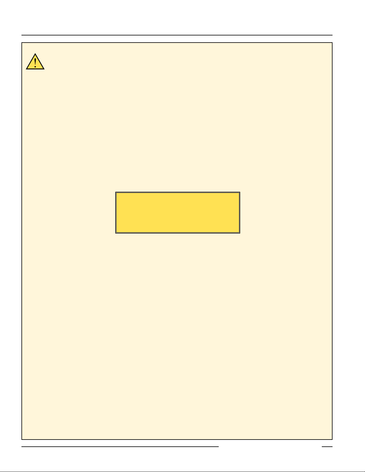
SI-LS42 Series Locking Style Switch
Models
For the following models, the actuator is mechanically locked when it is fully inserted into the actuator head. The actuator is unlocked by
applying voltage to the solenoid.
Kit
Model
†
Solenoid
Voltage
SI-LS42DMSG 24V ac/dc
SI-LS42UMSG
24-48V dc
24-230V ac
SI-LS42DMSGF 24V ac/dc
SI-LS42UMSGF
24-48V dc
24-230V ac
SI-LS42DMSH 24V ac/dc
SI-LS42UMSH
24-48V dc
24-230V ac
SI-LS42DMSHF 24V ac/dc
SI-LS42UMSHF
24-48V dc
24-230V ac
Actuator
†
Type
SI-QM-SSA
Rigid
In-Line
SI-QM-SMFA
Flexible
In-Line
SI-QM-SSA
Rigid
In-Line
SI-QM-SMFA
Flexible
In-Line
Interlock
†
Body
SI-LS42DSG
SI-LS42USG
SI-LS42DSG
SI-LS42USG
SI-LS42DSH
SI-LS42USH
SI-LS42DSH
SI-LS42USH
Contact
Configuration
(Actuator Engaged
and Locked)
Contact
Configuration
(Actuator Unlocked
and Removed)
Actuator Contacts Actuator Contacts
Solenoid Monitor
Contacts
Solenoid Monitor
Contacts
Actuator Contacts Actuator Contacts
Solenoid Monitor
Contacts
Solenoid Monitor
Contacts
Switching
Diagram*
SI-LS42DMSI 24V ac/dc
SI-LS42UMSI
24-48V dc
24-230V ac
SI-LS42DMSIF 24V ac/dc
SI-LS42UMSIF
24-48V dc
24-230V ac
SI-QM-SSA
Rigid
In-Line
SI-QM-SMFA
Flexible
In-Line
SI-LS42DSI
SI-LS42USI
SI-LS42DSI
SI-LS42USI
Actuator Contacts Actuator Contacts
Solenoid Monitor
Contacts
Solenoid Monitor
Contacts
Actuator Contacts Actuator Contacts
SI-QM-SSA
SI-LS42DMSJ
Rigid
In-Line
24V ac/dc
SI-QM-SMFA
SI-LS42DMSJF
†
A kit contains an interlock and actuator. Individual interlock bodies and actuators
are for replacement purposes only. See Warning on page 12.
Banner Engineering Corp. • Minneapolis, MN U.S.A.
P/N 60099 rev. D 3
www.bannerengineering.com • Tel: 763.544.3164
Flexible
In-Line
SI-LS42DSJ
Solenoid Monitor
Contacts
Solenoid Monitor
Contacts
*Contacts: Open Closed Transition
Page 4
Machine Safety Switches –
0 (0)
7.0 (0.28)
8.0 (0.31)
9.0 (0.35)
41 (1.61)
mm (in)
Engaged
Disengaged
21-22
13-14
Safety
Monitor
0 (0)
41 (1.61)
mm (in)
Engaged
Disengaged
11-12
21-22
Safety
Safety
7.0 (0.28)
9.0 (0.35)
0 (0)
41 (1.61)
mm (in)
Engaged
Disengaged
31-32
13-14
Safety
Monitor
21-22
Safety
7.0 (0.28)
8.0 (0.31)
9.0 (0.35)
0 (0)
41 (1.61)
mm (in)
Engaged
Disengaged
11-12
31-32
Safety
Safety
21-22
Safety
7.0 (0.28)
9.0 (0.35)
13 14
21 22
13 14
21 22
21 22
11 12
43 44
31 32
E1
+
E2
-
43 44
31 32
E1
+
E2
-
21 22
31 32
13 14
41 42
E1
+
E2
-
41 42
E1
+
E2
-
21 22
31 32
11 12
21
22
11 12
31 32
21 22
11 12
21
22
31 32
13 14
43 44
31 32
E1
+
E2
-
43 44
31 32
E1
+
E2
-
41 42
E1
+
E2
-
41 42
E1
+
E2
-
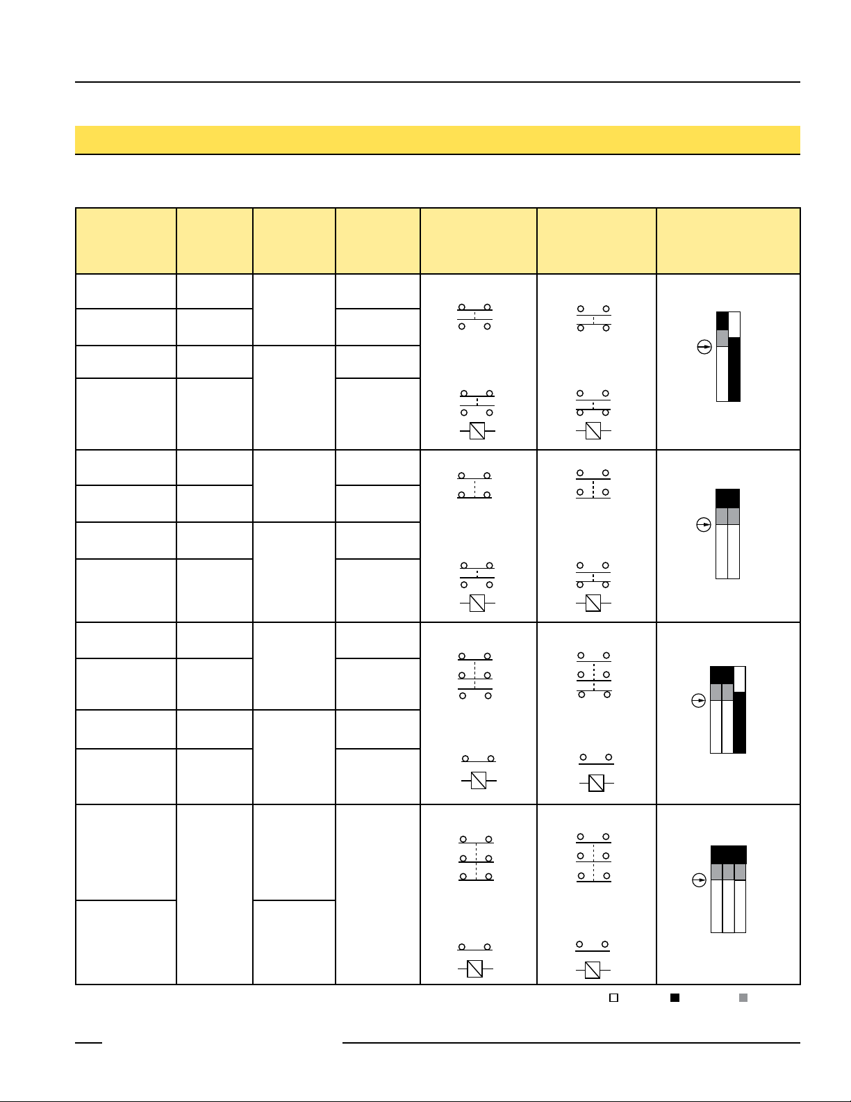
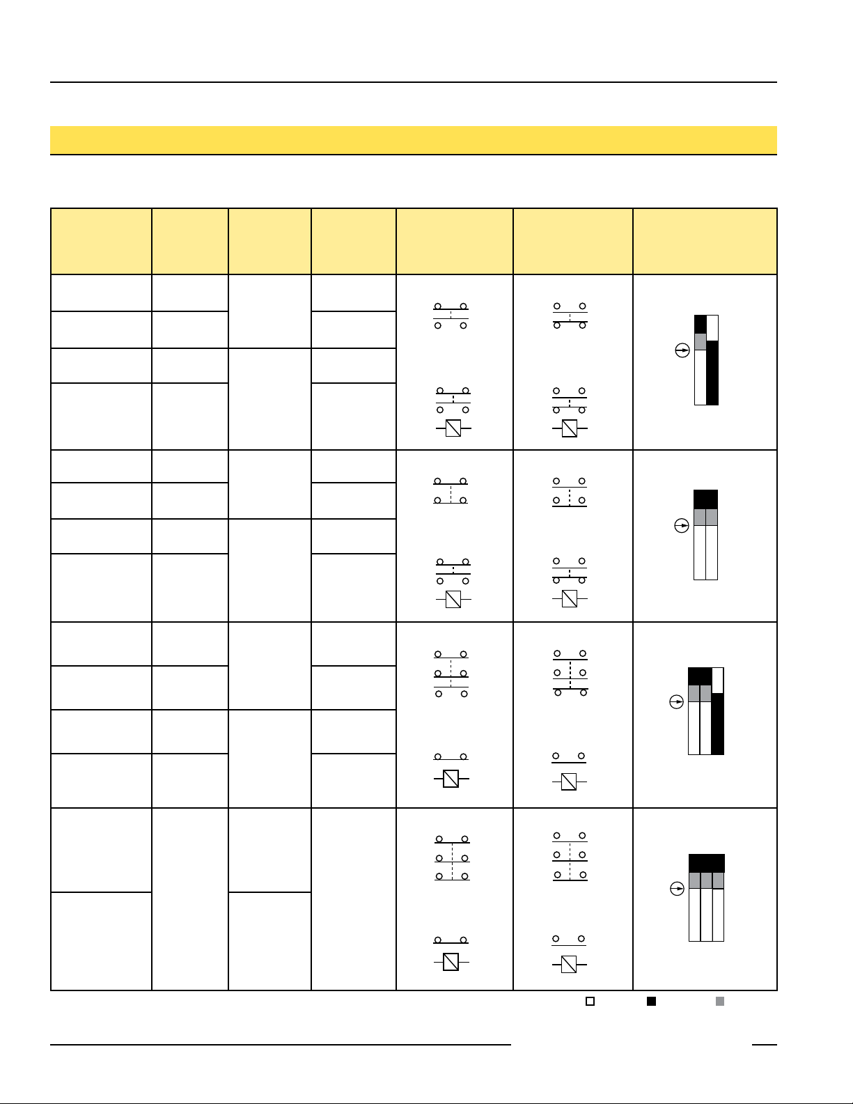
SI-LS42 Series Locking Style Switch
Models
For the following models, the fully inserted actuator is locked when voltage is applied to the solenoid. The actuator is unlocked when
voltage is removed from the solenoid.
Kit
Model
†
Solenoid
Voltage
SI-LS42DMMG 24V ac/dc
SI-LS42UMMG
24-48V dc
24-230V ac
SI-LS42DMMGF 24V ac/dc
SI-LS42UMMGF
24-48V dc
24-230V ac
SI-LS42DMMH 24V ac/dc
SI-LS42UMMH
24-48V dc
24-230V ac
SI-LS42DMMHF 24V ac/dc
SI-LS42UMMHF
24-48V dc
24-230V ac
Actuator
†
Type
SI-QM-SSA
Rigid
In-Line
SI-QM-SMFA
Flexible
In-Line
SI-QM-SSA
Rigid
In-Line
SI-QM-SMFA
Flexible
In-Line
Interlock
†
Body
SI-LS42DMG
SI-LS42UMG
SI-LS42DMG
SI-LS42UMG
SI-LS42DMH
SI-LS42UMH
SI-LS42DMH
SI-LS42UMH
Contact
Configuration
(Actuator Engaged
and Locked)
Contact
Configuration
(Actuator Unlocked
and Removed)
Actuator Contacts Actuator Contacts
Solenoid Monitor
Contacts
Solenoid Monitor
Contacts
Actuator Contacts Actuator Contacts
Solenoid Monitor
Contacts
Solenoid Monitor
Contacts
Switching
Diagram*
SI-LS42DMMI 24V ac/dc
SI-QM-SSA
SI-LS42DMI
Rigid
Actuator Contacts Actuator Contacts
SI-LS42UMMI
24-48V dc
24-230V ac
SI-LS42DMMIF 24V ac/dc
In-Line
SI-QM-SMFA
SI-LS42UMI
Solenoid Monitor
SI-LS42DMI
Flexible
SI-LS42UMMIF
24-48V dc
24-230V ac
In-Line
SI-LS42UMI
Actuator Contacts Actuator Contacts
SI-QM-SSA
SI-LS42DMMJ
Rigid
In-Line
24V ac/dc
SI-LS42DMJ
Solenoid Monitor
SI-QM-SMFA
SI-LS42DMMJF
Flexible
In-Line
†
A kit contains an interlock and actuator. Individual interlock bodies and actuators
are for replacement purposes only. See Warning on page 12.
4 P/N 60099 rev. D
Contacts
Contacts
Solenoid Monitor
Contacts
Solenoid Monitor
Contacts
*Contacts: Open Closed Transition
Banner Engineering Corp. • Minneapolis, MN U.S.A.
www.bannerengineering.com • Tel: 763.544.3164
Page 5

Machine Safety Switches –
Install
Tamper-Proof
Screw
Install
Tamper-Proof
Screw
0°
1.
2.
270°
90°
Holding
Clamp
180°
Pull Out
2
1
3
4
Figure 1. Horizontal actuator head position
(as received from the factory):
Install tamper-proof screw.
Figure 2. To change actuator head
orientation
SI-LS42 Series Locking Style Switch
Mechanical Installation
Horizontal or Vertical Actuation
Before installation, orient the switch actuator head for either horizontal (at a right angle
to the switch length) or vertical (in-line with the switch length) actuation. The switch is
shipped with the actuator head in the horizontal position (Figure 1). If this is the desired
orientation, install the M3 x 15 mm tamper-proof (one-way) screw, which is found in a
plastic bag, stored in the wiring chamber (see page 6 for information on opening the
wiring chamber access door).
If vertical actuation is required, remove the head by pulling straight up and off (Figure 2).
Re-orient the actuator head, and slide it back on in the new position until it snaps into
place. Install the tamper-proof screw, as shown in Figure 3.
Rotating Actuator Head to Desired Position
The actuator head may be rotated in increments of 90° to create eight possible actuator
engagement positions (i.e., four horizontal plus four vertical positions). To rotate the
head, pull the holding clamp forward, rotate the head (in either direction) to the desired
position, and push the holding clamp back in to lock. The head may be rotated with the
actuator either engaged or removed (Figure 4).
Installing the Switch and Actuator
NOTE: All mounting hardware is supplied by the switch user. The fasteners must be of
sufficient strength to avoid incidental breakage. Use of permanent fasteners or
locking hardware is recommended to prevent loosening or displacement of the
actuator and switch body.
The mounting holes in the switch body accept M5 (#10) screws. There are four holes
on a mounting pattern of 30 x 124 mm (see dimension drawing of switch, page 10). See
page 11 for dimensions of the actuator mounting holes.
Position the switch, with its actuator fully engaged, at the mounting location and mark
the mounting holes. Fasten the switch body and the actuator in place. The rigid in-line
actuator includes floating sleeves in the mounting holes to allow some forgiveness for
switch-to-actuator alignment. If the rigid in-line actuator is used, take care to not overtighten the actuator fasteners so as to allow this movement. After the mounting hardware
is secure, check the actuator/switch engagement for misalignment and binding.
Figure 3. Vertical actuator head position:
Install tamper-proof screw.
IMPORTANT: A safety switch must be installed in a manner which discourages
tampering or defeat. Mount each switch to prevent bypassing of the switching
function at the wiring chamber. A switch and its actuator must never be used as a
mechanical stop.
Manual Release for Spring Lock Models
Models with spring lock/solenoid unlock may be unlocked manually by rotating the unlock
mechanism, using an M3 Allen wrench (not supplied). First loosen the security screw
(see dimension drawing of switch, page 10), then turn the unlock mechanism in either
direction to the position.
IMPORTANT: After the switch is installed, check to be certain that the unlock
mechanism is in the position, and that the security screw is tight and covered with
Figure 4. Actuator head rotation
Banner Engineering Corp. • Minneapolis, MN U.S.A.
P/N 60099 rev. D 5
www.bannerengineering.com • Tel: 763.544.3164
tamper-resistant lacquer (user-supplied).
Page 6

Machine Safety Switches –
Safety Switch #1
Safety Switch #2
Input
Channel
#1
Input
Channel
#2
2-channel Safety Module
(2-channel E-stop Module
2-channel Gate Monitor Module, etc.)
Single gate
or guard
Solenoid
Monitor
Contact
Solenoid
Monitor
Contact
Actuator
Safety
Contact
Actuator
Safety
Contact
SI-LS42 Series Locking Style Switch
Electrical Installation
Access to Wiring Chamber
The wiring chamber is accessed via the hinged door. Simply insert a flat-blade
screwdriver, as shown in Figure 5, and pry gently down to open. Select the best wiring
entrance and thread in the ½" x 14 NPSM conduit adapter (supplied), or the optional M20
x 1.5 cable gland (page 12). The switch knockout will break loose with the final turn of
the conduit adapter or cable gland.
To open wiring chamber:
1. Insert the screwdriver
blade into slot in cover to
pry cover open.
To connect wires to terminals:
1. Insert the screwdriver blade into the slot below the
desired wiring terminal.
2. Twist the screwdriver blade in the slot to open the
terminal jaws; insert wire.
3. Hold wire in place and remove screwdriver.
CAUTION . . .
Electrical Installation
Two safety switches
must be used for each interlock guard
to achieve control reliability or Safety
Category 4 (per ISO 13849-1, EN 954-1) of
a machine stop circuit. Use of only one
safety switch per interlock guard is not
recommended.
In addition, normally-closed safety contacts
from each of the two safety switches should
be connected to the two separate inputs of a
2-channel safety module or safety interface,
as illustrated in Figure 6. This is required to
provide monitoring for safety switch contact
failure, and to provide the necessary reset
routine, as required by IEC 60204-1 and
NFPA 79 machine safety standards.
Figure 5. Access to wiring chamber – use a small flat-blade screwdriver
NOTE: Refer to the installation instructions provided with the safety module for information
Figure 6. Connect two redundant safety switches per interlock guard to an appropriate
6 P/N 60099 rev. D
regarding the interface of the safety module to the machine stop control elements.
2-channel input safety module.
WARNING . . .
Series
Connection of Safety
Interlock Switches
Monitoring multiple guards with a series
connection of multiple safety interlock
switches is not a Safety Category 4
Application (per ISO 13849-1, EN 954-1).
A single failure may be masked or
not detected at all. When such a
configuration is used, procedures must
be performed regularly to verify proper
operation of each switch.
Banner Engineering Corp. • Minneapolis, MN U.S.A.
www.bannerengineering.com • Tel: 763.544.3164
Page 7

Machine Safety Switches –
SI-LS42 Series Locking Style Switch
WARNING . . .
It must not be possible for
personnel to reach any
hazard point through an opened guard
(or any opening) before hazardous
machine motion has completely stopped.
Please reference OSHA CFR 1910.217
and ANSI B11 standards (see page 2) for
information on determining safety distances
and safe opening sizes for your guarding
devices.
Connection to a Machine
Four contacts are offered. Two are safety contacts which must be wired in series, and
the other two are considered monitoring contacts which may be used, if desired.
The contact between terminals 11 and 12 or 21 and 22 is a safety contact which is
closed (i.e., it conducts) when the actuator is engaged. The contact between terminals 13
and 14 is the associated actuator monitoring contact.
The contact between terminals 31 and 32 is a safety contact which is closed when
the solenoid is in its locking state. The contact between terminals 43 and 44 is the
associated solenoid monitoring contact.
See the switching diagrams on pages 3 and 4 for contact state information.
Solenoid voltage connects to terminals E1 (+) and E2 (-).
As illustrated in Figure 6, the normally-closed safety contacts (i.e., safety contacts that
are closed when the actuator is engaged and the solenoid is in its locking state) from
each of two safety switches per interlock guard must connect to a 2-channel safety
module or safety interface in order to achieve a control reliable interface to the master
stop control elements of a machine.
Examples of appropriate safety modules include 2-channel emergency stop (E-stop)
safety modules and gate monitor safety modules.
Two functions of the safety module or safety interface are:
1. To provide a means of monitoring the contacts of both safety switches for contact
failure, and to prevent the machine from restarting if either switch fails; and
2. To provide a reset routine after closing the guard and returning the safety contacts to
their closed position. This prevents the controlled machinery from restarting by simply
reinserting the safety switch actuators. This necessary reset function is required by
ANSI B11 and NFPA 79 machine safety standards.
Use only positively-driven, normally-closed safety contacts from each switch for
connection to the safety module. The normally-open contacts may be used for control
functions that are not safety-related. A typical use is to communicate with a process
controller. Refer to the installation instructions provided with the safety modules for more
information regarding the interface of the safety module to the machine stop control
elements.
Banner Engineering Corp. • Minneapolis, MN U.S.A.
P/N 60099 rev. D 7
www.bannerengineering.com • Tel: 763.544.3164
Page 8

Machine Safety Switches –
SI-LS42 Series Locking Style Switch
Periodic Checks
Periodic checks should be performed only by Designated Persons or Qualified Persons,
as specified below. Safety switches should be checked at each shift change or machine
setup by a Designated Person (see below) for:
1. Breakage of the switch body or actuator,
2. Good alignment and full engagement of the actuator with the receptor,
3. Confirmation that the safety switch is not being used as an end stop,
4. Loosening of the switch or actuator mounting hardware, and
5. Verification that it is not possible to reach any hazard point through an opened guard
(or any opening) before hazardous machine motion has completely stopped.
In addition, a Qualified Person should check for the following on a periodic schedule,
determined by the user, based upon the severity of the operating environment and the
frequency of switch actuations:
1. Check the wiring chamber for signs of contamination.
2. Check the contacts for signs of deterioration or damage.
3. Inspect the electrical wiring for continuity and damage.
4. Verify that wiring conforms to the instructions on pages 8 to 10 of this data sheet.
A Designated Person is identified in writing by the employer as being appropriately
trained to perform a specified checkout procedure. A Qualified Person possesses a
recognized degree or certificate or has extensive knowledge, training, and experience to
be able to solve problems relating to the safety switch installation (ANSI B30.2).
Repairs
NOTE: Do not attempt any repairs to the switch. It contains no field-replaceable
components. Return the switch to the factory for warranty repair or replacement.
If it ever becomes necessary to return a switch to the factory, please do the following:
1. Contact the Banner applications engineering department at the number or address
listed on the front cover. They will attempt to troubleshoot the system from your
description of the problem. If they conclude that a component is defective, they will
issue an RMA (Return Merchandise Authorization) number for your paperwork, and
give you the proper shipping address.
2. Pack the switch carefully. Damage which occurs in shipping is not covered by warranty.
8 P/N 60099 rev. D
Banner Engineering Corp. • Minneapolis, MN U.S.A.
www.bannerengineering.com • Tel: 763.544.3164
Page 9

Machine Safety Switches –
SI-LS42 Series Locking Style Switch
Specifications
Contact Rating 4A @ 250V ac max.
2.5 kV max. transient tolerance
NEMA A300 P300
European Rating Utilization categories: AC15 and DC13 (IEC 60947-5-1)
Switches with 1 and 2 contact pairs:
= 250V ac
U
i
I
= 2.5A
th
Contact Material Silver-nickel alloy
Solenoid Power
Consumption
Maximum Actuator Speed 1.5 m/second (5'/second)
Minimum Actuator
Engagement Radius
Actuator Extraction Force 2000 Newtons (440 lbf) when locked
Short Circuit Protection 6 amp Slow Blow, 10 amp Fast Blow. Recommended external fusing or overload protection.
Mechanical Life 1 million operations
Wire Connections 10 cage clamp elements
Cable Entry M20 x 1.5 threaded entrance. Adapter supplied to convert M20 x 1.5 to ½" - 14 NPT threaded entrance.
Construction Glass fiber-reinforced polymide thermoplastic housing; UL 94-V0 rating
Environmental Rating IEC IP67
Operating Conditions Temperature:
Weight 0.3 kg
Certifications
1.1 VA / Inrush 56 VA (0.2 sec)
In-line actuators: 400 mm (16")
Flexible actuators: 150 mm (6")
1.5 mm stranded max. / 16 AWG
-30° to +70° C (-22° to +158° F)
Ue
24 4 3
110 4 0.77
230 4 0.3
40-60 Hz
Ie/AC-15 AIe/DC-13
V
A
Banner Engineering Corp. • Minneapolis, MN U.S.A.
P/N 60099 rev. D 9
www.bannerengineering.com • Tel: 763.544.3164
Page 10

Machine Safety Switches –
40-46 mm
(1.6-1.8")
M20 x 1.5
45.0 mm
(1.77")
37.5 mm
(1.48")
15.0 mm (0.59")
*Found only on spring lock/solenoid unlock models.
19.5 mm
(0.76")
29.0 mm
(1.14")
29.0 mm
(1.14")
30-40 mm
(1.18"-1.58")
51.0 mm
(2.00")
21.0 mm
(0.83")
5.0 mm
(0.20")
135.0 mm
(5.32")
170.0 mm
(6.70")
66.0 mm ± 10
(2.60" ± 0.4")
Ø 5.3 mm
(0.21")
2.0 mm
(0.08")
32.0 mm
(1.26")
124.0 mm
(4.89")
184 mm
(7.25")
Unlocking
Mechanism*
Security
Screw*
5.0 mm
(0.20")
30.0 mm
(1.18")
42.5 mm
(1.67")
See page 11 for actuator dimensions
Model SI-LS42.. Interlock Body
SI-LS42 Series Locking Style Switch
Dimensions
10 P/N 60099 rev. D
Banner Engineering Corp. • Minneapolis, MN U.S.A.
www.bannerengineering.com • Tel: 763.544.3164
Page 11

Machine Safety Switches –
20.0 mm
(0.79")
7.5 mm
(0.30")
15 mm
(0.59")
80.0 mm
(3.13")
ø 4.8 mm
(2 Holes)
40 mm
(1.6")
29 mm
(1.1")
C
L
50 mm
(2.0")
81 mm
(3.2")
41 mm
(1.6")
ø 5.5 mm
(0.22")
Actuator Dimensions
SI-LS42 Series Locking Style Switch
SI-QM-SSA Rigid In-Line Actuator
400 mm (16") minimum actuator engagement radius
SI-QM-SMFA Flexible In-line Actuator
150 mm (6") minimum actuator engagement radius
The flexible actuator mounting flange may be rotated
90° with respect to the actuator position. To rotate, push the flange in the
direction of actuation, turn the flange either direction, and release to lock
the flange in the new position; see the diagram above.
Banner Engineering Corp. • Minneapolis, MN U.S.A.
P/N 60099 rev. D 11
www.bannerengineering.com • Tel: 763.544.3164
Page 12

Machine Safety Switches –
®
25.0 mm
(0.98")
M20 x 1.5
24.0 mm
(0.94")
1/2"-14 NPT
Internal Thread
M20 x 1.5
25.0 mm
(0.98")
37.0 mm
(1.46")
Size Model
Used with
Switch Models
SI-LS42 Series Locking Style Switch
Accessories
Cable Glands
For Cable
Diameters
Dimensions
M20 x 1.5
Plastic
SI-QS-CGM20 All
Description Model
½"-14 NPT
Plastic
Conduit Adaptor
Replacement
Terminal Cover
SI-QS-M20 All
SI-LS42-COVER All N/A
Description Model
5.0 to 12.0 mm
(0.20" to 0.47")
Replacement Parts
Used with
Switch Models
Accessory Actuators
Dimensions
Used with
Switch Models
Rigid In-line metal actuator used for doors or
covers. Slide-bolt design for use in heavy-duty
applications where alignment is difficult to maintain.
SI-QM-SB All
WARNING . . .
Spare actuators must NEVER be used to bypass or otherwise defeat the protective function of a safety switch. To do so may create an
unsafe situation which could lead to serious injury or death.
WARRANTY:
free of charge, any product of its manufacture found to be defective at the time it is returned to the factory during the warranty period. This warranty
does not cover damage or liability for the improper application of Banner products. This warranty is in lieu of any other warranty either expressed or
implied.
P/N 60099 rev. D
Banner Engineering Corp., 9714 Tenth Ave. No., Minneapolis, MN USA 55441 • Phone: 763.544.3164 • www.bannerengineering.com • Email: sensors@bannerengineering.com
Banner Engineering Corp. warrants its products to be free from defects for one year. Banner Engineering Corp. will repair or replace,
 Loading...