

Page 1
Machine Safety Switches
®
23 24
11 12
0°
23 24
11 12
0°
90°90°
±8°
±5°
0°
±10°
±90°
11-12
23-24
Safety
Monitor
21 22
11 12
0°
21 22
11 12
0°
90°90°
±8°
±5°
0°
±90°
11-12
21-22
Safety
Monitor
Safety
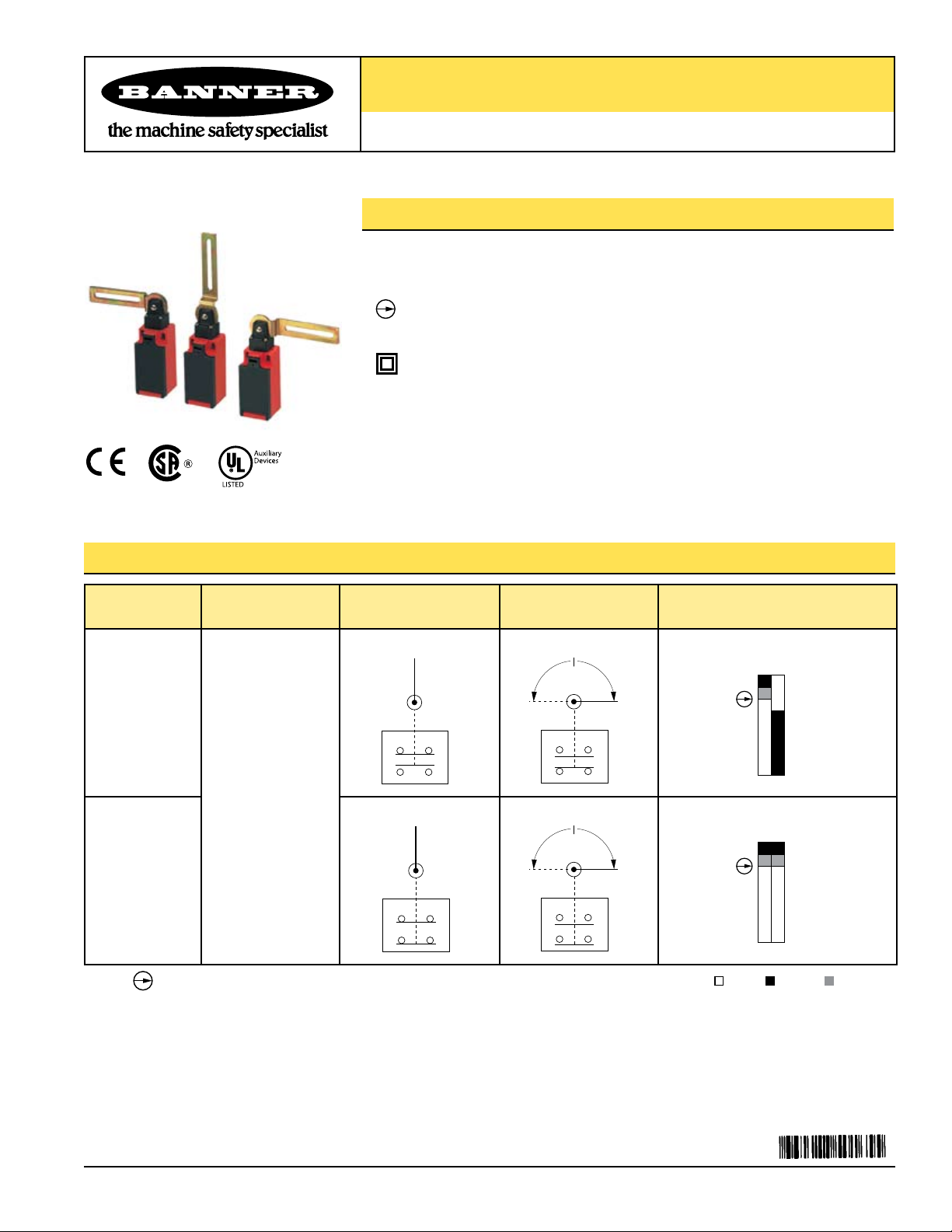
SI-LS31H Series 31 mm Limit-Switch-Style with Hinged Lever Actuators
Features
• Limit switch design (EN 50047)
• For use on doors or flaps
•
Positive opening safety contacts (IEC 60947-5-1) (not dependent upon springs)
• Glass-reinforced thermoplastic switch housing with plated steel actuator
• Insulated device (IEC 60947-5-1) on all models with plastic housings
• Actuator head rotatable in 90 degree increments
Models
Model Actuator
Contact Configuration
(Lever in Normal Position)
SI-LS31HGD
Vertical Hinged
Lever ±90°
SI-LS31HGE
NOTE: This symbol for a positive opening safety contact (IEC 60947-5-1) is used in the
switching diagrams to identify the point in actuator travel where the normally closed
safety contact is fully open.
Contact Configuration
(Lever Rotated)
Switching Diagram
Contacts: Open Closed Transition
Printed in USA 07/06 P/N 50165 rev. D
Page 2
Machine Safety Switches –
SI-LS31H Series
Important Information Regarding the Use of Safety Switches
In the United States, the functions that Banner safety switches are intended to perform are regulated by the Occupational Safety and Health
Administration (OSHA). Whether or not any particular safety switch installation meets all applicable OSHA requirements depends upon factors
that are beyond the control of Banner Engineering Corp. These factors include the details of how the safety switches are applied, installed, wired,
operated, and maintained.
Banner Engineering Corp. has attempted to provide complete application, installation, operation, and maintenance instructions. This information is
found in the instruction manual packaged with each safety switch. In addition, we suggest that any questions regarding the use or installation of
safety switches be directed to the factory applications department at the telephone numbers or address shown below.
Banner Engineering Corp. recommends that safety switches be applied according to the guidelines set forth in international (ISO/IEC) standards
listed below. Specifically, Banner Engineering Corp. recommends application of these safety switches in a configuration which meets safety
category 4, per ISO 13849 (EN954-1).
In addition, the user of Banner safety switches has the responsibility to ensure that all local, state, and national laws, rules, codes, and regulations
relating to the use of Banner safety switches in any particular application are satisfied. Extreme care is urged that all legal requirements have been
met and that all installations and maintenance instructions are followed.
Application Assistance
Toll Free: 1-888-3-SENSOR (1-888-373-6767)
Email: sensors@bannerengineering.com
Address: 9714 Tenth Avenue North
Minneapolis, MN 55441
U.S. Regulations Applicable to Use of Banner Safety Switches
OSHA Code of Federal Regulations: Title 29, Parts 1900 to 1910
Available from: Superintendent of Documents
Government Printing Office
P.O. Box 371954
Pittsburgh, PA 15250-7954
Tel: 202-512-1800
U.S. Standards Applicable to Use of Banner Safety Switches
ANSI B11 “ Standards for Construction, Care, and Use of Machine Tools”
Available from: Safety Director
AMT
7901 Westpark Drive
McLean, VA 22102
Tel: 703-893-2900
Applicable European and International Standards
ISO/TR 12100-1 “Safety of Machinery
(EN292-18-2)
ISO 13852 (EN 294) “Safety of Machinery—Safety Distances to Prevent Danger Zones Being Reached by the Upper Limbs”
ISO 13853 (EN 811) “Safety of Machinery
ISO 13849 (EN 954-1) “Safety of Machinery
ISO 13855 (EN 999) “ Safety of Machinery
Human Body”
ISO 14119 (EN 1088) “Safety of Machinery
IEC/EN 60204-1 “Safety of Machinery
IEC/EN 60947-5-1 “Low Voltage Switchgear
—The Association for Manufacturing Technology
—Basic Concepts, General Principles for Design”
—Safety Distances to Prevent Danger Zones Being Reached by the Lower Limbs”
—Safety Related Parts of Control Systems”
—The Positioning of Protective Equipment in Respect to Approach Speeds of Parts of the
—Interlocking Devices Associated with Guards—Principles for Design and Selection”
—Electrical Equipment of Machines”
—Electromechanical Control Circuit Devices”
Available from: Global Engineering Documents
15 Inverness Way East
Englewood, CO 80112-5704
Phone: 1-800-854-7179
Fax: 303-397-2740
2 P/N 50165 rev. D
Banner Engineering Corp. • Minneapolis, MN U.S.A.
www.bannerengineering.com • Tel: 763.544.3164
Page 3
Machine Safety Switches –
23 24
11 12
0°
23 24
11 12
0°
23 24
11 12
180°
0°
23 24
11 12
180°
0°
8°
5°
0°
10°
180°
11-12
23-24
Safety
Monitor
8°
5°
0°
10°
180°
11-12
23-24
Safety
Monitor
21 22
11 12
0°
21 22
11 12
180°
0°
8°
5°
0°
180°
11-12
21-22
Safety
Safety
21 22
11 12
0°
21 22
11 12
180°
0°
8°
5°
0°
180°
11-12
21-22
Safety
Safety
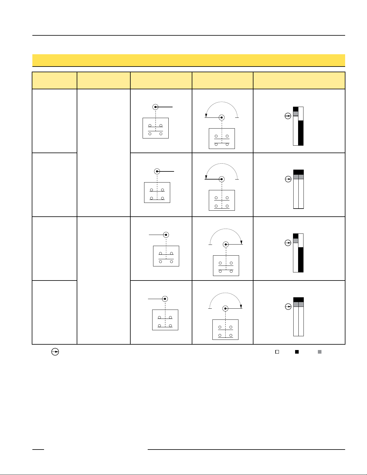
Models
SI-LS31H Series
Model Actuator
SI-LS31HGRD
Hinged Lever 180°
SI-LS31HGRE
SI-LS31HGLD
Right-hand
Contact Configuration
(Lever in Normal Position)
Contact Configuration
(Lever Rotated)
Switching Diagram
Left-hand
Hinged Lever 180°
SI-LS31HGLE
NOTE: This symbol for a positive opening safety contact (IEC 60947-5-1) is used in the
Contacts: Open Closed Transition
switching diagrams to identify the point in actuator travel where the normally closed
safety contact is fully open.
Banner Engineering Corp. • Minneapolis, MN U.S.A.
P/N 50165 rev. D 3
www.bannerengineering.com • Tel: 763.544.3164
Page 4

Machine Safety Switches –
Safety
Switch
#1
Safety
Switch
#2
Input
Channel
#1
Input
Channel
#2
2-channel Safety Module
(2-channel E-stop Module
2-channel Gate Monitor Module, etc.)
Single gate
or guard
11
12
11
12
SI-LS31H Series
Overview
Series SI-LS31H safety interlock switches have a built-in hinged lever actuator that
mounts to a hinged door or flap to detect its being opened. The actuator head may be
rotated on the interlock body in any of four positions (see Figure 1).
Mechanical Installation
1. With actuator in the normal position, loosen the four screws holding the actuator head
to the switch body and carefully rotate the actuator head to the desired position (see
Figure 1). Re-tighten the four screws.
2. User tamper-resistant hardware, such as one-way screws, to attach lever actuator and
to mount the switch body.
3. If possible, align lever pivot point with the axis of the door or flap.
IMPORTANT: A safety switch must be installed in a manner which discourages
tampering or defeat. Mount each switch to prevent bypassing of the switching
function at the terminal chamber. Overtravel may cause damage to switch.
Model SI-LS31HGD is used on doors or flaps which open a maximum of 90° in either
direction, beginning with the lever in a vertical position (see Figure 2, top).
Models SI-LS31HGRD and SI-LS31HGLD are used on doors and flaps which open in
one direction, beginning with the lever in a horizontal position (see Figure 2, bottom).
Actuator head may be rotated
in 90° increments.
Figure 1. Features
Model
SI-LS31HGD
Models
SI-LS31HGRD
SI-LS31HGLD
Electrical Installation
Access to the Wiring Chamber
The wiring chamber is accessed via a hinged cover door which may be pried open using
a flat-blade screwdriver (see the dimension drawings on page 7). A conduit adapter is
supplied to convert the German M20 x 1.5 thread to ½" x 14 NPT. An accessory cable
gland which fits the M20 x 1.5 thread is available (see page 7).
Connection to a Machine
Two types of contacts are offered. The contacts between terminals 11–12 and 21–22
are the safety contacts, which are closed (i.e., they conduct) when the actuator is in
the home (0°) position. The contacts located between terminals 23–24 are considered
monitoring contacts, which should not be used for safety switching.
As illustrated in Figure 3, a normally-closed safety contact (i.e., a safety contact that is
closed when the actuator is in the home [0°] position) from each of two safety switches
per interlock guard must connect to a 2-channel safety module or safety interface in
order to achieve a control reliable interface to the master stop control elements of a
machine. Examples of appropriate safety modules include 2-channel emergency stop
(E-stop) safety modules and gate monitor safety modules.
Two functions of the safety module or safety interface are:
1. to provide a means of monitoring the contacts of both safety switches for contact
2. to provide a reset routine after closing the guard and returning the safety switch
4 P/N 50165 rev. D
failure, and to prevent the machine from restarting if either switch fails; and
contacts to their closed position. This prevents the controlled machinery from restarting
by simply moving the safety switch actuators. This necessary reset function is required
by ANSI B11 and NFPA 79 machine safety standards.
Figure 2. Door opens in one direction
NOTE: Refer to the installation
instructions provided with the
safety module for information
regarding the interface of the
safety module to the machine stop
control elements.
Figure 3. Connect two redundant safety
switches per interlock guard to an
appropriate 2-channel input safety
module.
Banner Engineering Corp. • Minneapolis, MN U.S.A.
www.bannerengineering.com • Tel: 763.544.3164
Page 5

Machine Safety Switches –
SI-LS31H Series
CAUTION . . .
Electrical Installation
Two safety switches must be
used for each interlock guard to achieve
control reliability or Safety Category 4 (per
ISO 13849-1, EN 954-1) of a machine stop
circuit. Use of only one safety switch per
interlock guard is not recommended.
In addition, normally-closed safety contacts
from each of the two safety switches should be
connected to the two separate inputs of a
2-channel safety module or safety interface,
as illustrated in Figure 6. This is required to
provide monitoring for safety switch contact
failure, and to provide the necessary reset
routine, as required by IEC 60204-1 and
NFPA 79 machine safety standards.
WARNING . . .
Connection of Safety
Interlock Switches
Monitoring multiple guards with a series
connection of multiple safety interlock
switches is not a Safety Category 4
Application (per ISO 13849-1, EN 954-1).
A single failure may be masked or not
detected at all. When such a configuration
is used, procedures must be performed
regularly to verify proper operation of each
switch.
Series
Use only a positively driven, normally closed safety contact from each switch for
connection to the safety module. The normally open contact may be used for control
functions that are not safety-related. A typical use is to communicate with a process
controller. Refer to the installation instructions provided with the safety modules for more
information regarding the interface of the safety module to the machine stop control
elements.
Periodic Checks
Safety switches should be checked at each shift change or machine setup by a
designated person (see below) for:
1. Breakage of the switch body or actuator,
2. Good alignment and full engagement of the actuator with the receptor,
3. Confirmation that the safety switch is not being used as an end stop,
4. Loosening of the switch or actuator mounting hardware, and
5. Verification that it is not possible to reach any hazard point through an opened guard
(or any opening) before hazardous machine motion has completely stopped.
In addition, a qualified person should check for the following on a periodic schedule
determined by the user based upon the severity of the operating environment and the
frequency of switch actuations:
1. Check the wiring chamber for signs of contamination.
2. Check the contacts for signs of deterioration or damage.
3. Inspect the electrical wiring for continuity and damage.
4. Verify that wiring conforms to the instructions on pages 4 and 5 of this data sheet.
A designated person is identified in writing by the employer as being appropriately trained
to perform a specified checkout procedure. A qualified person possesses a recognized
degree or certificate or has extensive knowledge, training, and experience to be able to
solve problems relating to the safety switch installation (ANSI B30.2).
WARNING . . .
It must not be possible for
personnel to reach any hazard
point through an opened guard (or any
opening) before hazardous machine motion
has completely stopped. Please reference
OSHA CFR 1910.217 and ANSI B11 standards
(see page 2) for information on determining
safety distances and safe opening sizes for
your guarding devices.
Do not attempt any repairs to the switch. It contains no field-replaceable
components. Return the switch to the factory for warranty repair or replacement.
If it ever becomes necessary to return a switch to the factory, please do the following:
1. Contact the Banner applications engineering department at the number or address
listed on the front cover. They will attempt to troubleshoot the system from your
description of the problem. If they conclude that a component is defective, they will
issue an RMA (Return Merchandise Authorization) number for your paperwork, and
give you the proper shipping address.
Repairs
2. Pack the switch carefully. Damage which occurs in shipping is not covered by
warranty.
Banner Engineering Corp. • Minneapolis, MN U.S.A.
P/N 50165 rev. D 5
www.bannerengineering.com • Tel: 763.544.3164
Page 6

Machine Safety Switches –
SI-LS31H Series
Specifications
Contact Rating 10A @ 24V ac, 10A @ 110V ac, 6A @ 230V ac
6A @ 24V dc
2.5 kV max. transient tolerance
NEMA A300 P300
European Rating Utilization categories: AC15 and DC13
U
= 500V ac
i
I
= 10A
th
Contact Material Silver-nickel alloy
Maximum Switching Speed 50 operations per minute
Required Actuation Force 15 N cm (1.3 lbf in)
Short Circuit Protection 6 amp Slow Blow, 10 amp Fast Blow. Recommended external fusing or overload protection.
Mechanical Life 1 million operations
Wire Connections Screw terminals with pressure plates accept the following wire sizes –
Stranded and solid: 20 AWG (0.5 mm2) to 16 AWG (1.5 mm2) for one wire
Stranded: 20 AWG (0.5 mm2) to 18 AWG (1.0 mm2) for two wires
Cable Entry M20 x 1.5 threaded entrance.
Adapter supplied to convert M20 x 1.5 to ½"-14 NPT threaded entrance
(See dimension drawings on page 7.)
Construction Glass fiber-reinforced thermoplastic UL94-VO rating; plated steel actuator
Environmental Rating IEC IP65
Operating Conditions Temperature:
Weight 0.09 Kg (0.20 lbs)
Certifications
-30° to +80° C (-22° to +176° F)
Ue
V
24 10 6
110 10 1
230 6 0.4
40-60 Hz
Ie/AC-15 AIe/AC-13
A
6 P/N 50165 rev. D
Banner Engineering Corp. • Minneapolis, MN U.S.A.
www.bannerengineering.com • Tel: 763.544.3164
Page 7

Machine Safety Switches –
M20 x 1.5
25.0 mm
(0.98")
37.0 mm
(1.46")
25.0 mm
(0.98")
M20 x 1.5
24.0 mm
(0.94")
1/2"-14 NPT
Internal Thread
22.0 mm
(0.87")
4.0 mm
(0.16")
62.0 mm
(2.44")
20.0 mm
(0.79")
5.1 mm
(0.20")
SI-LS31HGRD
SI-LS31HGLD
20.0 mm
(0.79")
31.0 mm
(1.22")
8.0 mm
(0.31")
ø 4.2 mm
(0.17")(2)
30.5 mm
(1.20")
70.0 mm
(2.76")
10.0 mm
(0.39")
2.5 mm
(0.10")
45 mm
(1.77")
93.5 mm
(3.68")
Slot for opening
cover to wiring chamber
(Use flat-blade screwdriver
and twist to open).
M20 x 1.5
(0.06")
1/2"-14 NPT
Adapter is Supplied
22.0 mm
(0.87")
4.0 mm
(0.16")
62.0 mm
(2.44")
160.0 mm
(8.30")
20.0 mm
(0.79")
5.1 mm
(0.20")
20.0 mm
(0.79")
31.0 mm
(1.22")
8.0 mm
(0.31")
ø 4.2 mm
(0.17") (2)
30.5 mm
(1.20")
70.0 mm
(2.76")
10.0 mm
(0.39")
2.5 mm
(0.10")
45.0 mm
(1.77")
Slot for opening
cover to wiring chamber
(Use flat-blade screwdriver
and twist to open).
M20 x 1.5
(0.06")
1/2"-14 NPT
Adapter is Supplied
Dimensions
SI-LS31H Series
Models SI-LS31HGRD/HGRE and HGLD/HGLE
Size Model
Used with
Switch Models
Model SI-LS31HGD/HGE
Accessories
Cable Glands
For Cable
Diameters
Dimensions
M20 x 1.5
Plastic
SI-QS-CGM20
All
5.0 to 12.0 mm
(0.20" to 0.47")
Replacement Parts
Size Model*
Used with
Switch Models
½"-14 NPT
Plastic
*NOTE: One conduit adapter is supplied with each switch.
Conduit Adapter
Banner Engineering Corp. • Minneapolis, MN U.S.A.
P/N 50165 rev. D 7
www.bannerengineering.com • Tel: 763.544.3164
SI-QS-M20
All
Thread
Conversion
M20 x 1.5 to
½"-14 NPT
Dimensions
Page 8

Machine Safety Switches –
®
SI-LS31H Series
WARRANTY: Banner Engineering Corp. warrants its products to be free from defects for one year. Banner Engineering Corp. will repair or replace,
free of charge, any product of its manufacture found to be defective at the time it is returned to the factory during the warranty period. This warranty
does not cover damage or liability for the improper application of Banner products. This warranty is in lieu of any other warranty either expressed or
implied.
P/N 50165 rev. D
Banner Engineering Corp., 9714 Tenth Ave. No., Minneapolis, MN USA 55441 • Phone: 763.544.3164 • www.bannerengineering.com • Email: sensors@bannerengineering.com
 Loading...