

Page 1

SC22-3/-3E Safety Controller Instruction Manual
P/N 133487 rev. C -- 10/7/2010
Original Instructions
Page 2

Contents
Contents
1 About This Document ..........................................................................................................6
1.1 Important . . . Read This Before Proceeding! ...........................................................................................6
1.1.1 Use of Warnings ..........................................................................................................................6
1.2 EC Declaration of Conformity (DOC) .......................................................................................................6
1.3 Standards and Regulations ......................................................................................................................7
1.3.1 U.S. Application Standards ..........................................................................................................7
1.3.2 OSHA Regulations ........................................................................................................................7
1.3.3 International/European Standards ................................................................................................7
1.3.4 Sources of Standards and Regulations ........................................................................................8
1.4 Contact Us ...............................................................................................................................................8
2 Overview ................................................................................................................................9
2.1 Ethernet-Compatible Model ......................................................................................................................9
2.2 Applications ............................................................................................................................................10
2.3 Design and Testing ................................................................................................................................10
2.4 Components ...........................................................................................................................................10
2.4.1 PC System Requirements ..........................................................................................................10
2.4.2 USB Connections .......................................................................................................................11
2.4.3 Ethernet Connections .................................................................................................................11
2.4.4 SC-XMP Programming Tool .......................................................................................................11
2.4.5 SC-XM1 External Memory (XM) Card ........................................................................................11
2.5 Configuring the Safety Controller ...........................................................................................................12
2.5.1 Onboard Interface (OBI) .............................................................................................................12
2.5.2 Personal Computer Interface (PCI) ............................................................................................14
2.6 Input and Output Connections ................................................................................................................15
2.6.1 Safety and Non-Safety Input Devices .........................................................................................15
2.6.2 Safety Outputs ...........................................................................................................................16
2.6.3 Status Outputs ............................................................................................................................17
2.6.4 Virtual Status Outputs .................................................................................................................17
2.6.5 I/O Mapping: the I/O Control Relationship ..................................................................................18
2.7 System Settings ......................................................................................................................................18
2.8 Internal Logic .........................................................................................................................................19
2.8.1 Additional Logic Functions ..........................................................................................................20
2.9 Password Overview ...............................................................................................................................20
2.10 Confirming a Configuration ..................................................................................................................20
3 Components and Specifications .......................................................................................21
3.1 Safety Controller Starter Kit Models .......................................................................................................21
3.2 Replacement Parts/Accessories .............................................................................................................21
3.3 Ethernet Cordsets ...................................................................................................................................22
3.4 Interface Modules ...................................................................................................................................22
3.4.1 Mechanically Linked Contactors .................................................................................................22
3.5 Specifications .........................................................................................................................................23
3.5.1 Dimensions ................................................................................................................................25
4 System Installation .............................................................................................................26
4.1 Appropriate Application ..........................................................................................................................26
4.2 Installing the Safety Controller ...............................................................................................................27
4.3 Safety Input Devices ...............................................................................................................................27
4.3.1 Signals: Run and Stop States .....................................................................................................28
4.3.2 Safety Input Device Properties ...................................................................................................28
4.4 Non-Safety Input Devices .......................................................................................................................31
4.5 Input Device Resets ...............................................................................................................................33
2 P/N 133487 rev. C
Page 3

Contents
4.5.1 Reset Signal Requirements ........................................................................................................34
4.5.2 Automatic and Manual Reset Inputs Mapped to the Same Safety Output .................................34
4.5.3 Perimeter Guarding and Pass-Through Hazards .......................................................................35
4.6 Safety Input Function ..............................................................................................................................35
4.6.1 Internal Logic .............................................................................................................................35
4.6.2 Two-Hand Control (THC) ............................................................................................................36
4.6.3 Enabling Devices ........................................................................................................................36
4.6.4 Mute Function ............................................................................................................................37
4.6.5 Bypass Function .........................................................................................................................38
4.6.6 Adjustable Valve Monitoring (AVM) Function .............................................................................39
4.7 EDM, OSSD (Safety Output), and FSD Hookup ....................................................................................40
4.7.1 External Device Monitoring (EDM) ............................................................................................40
4.7.2 Safety Outputs ...........................................................................................................................41
4.7.3 FSD Interfacing Connections .....................................................................................................43
4.7.4 Common Wire Installation ..........................................................................................................49
4.8 Status Outputs ........................................................................................................................................50
4.8.1 Status Output Signal Conventions .............................................................................................50
4.8.2 Status Output Functionality ........................................................................................................51
4.9 Virtual Status Outputs .............................................................................................................................52
4.10 Commissioning Checkout ....................................................................................................................52
5 PC Interface Configuration (PCI) .......................................................................................53
5.1 PC Interface (PCI) Overview ..................................................................................................................53
5.1.1 Configuration Tools .....................................................................................................................53
5.1.2 Build a Configuration ..................................................................................................................54
5.1.3 Revise an Existing Configuration ...............................................................................................59
5.1.4 Other Functions ..........................................................................................................................60
6 Onboard Interface Configuration (OBI) ............................................................................62
6.1 Onboard Interface (OBI) Overview .........................................................................................................62
6.2 Run Mode ...............................................................................................................................................64
6.3 Configuration Mode ................................................................................................................................64
6.3.1 Enter Controller Password ..........................................................................................................64
6.3.2 Configuration File ........................................................................................................................64
6.3.3 Confirm Configuration ................................................................................................................65
6.3.4 System Options .........................................................................................................................66
6.3.5 Exit Configuration ......................................................................................................................66
6.4 Edit Configuration ...................................................................................................................................66
6.4.1 Name Configuration ....................................................................................................................66
6.4.2 Inputs ..........................................................................................................................................66
6.4.3 Outputs/System Settings ...........................................................................................................67
6.4.4 Configuration Summary .............................................................................................................68
6.5 Add an Input ...........................................................................................................................................68
6.5.1 Add a Safety Input .....................................................................................................................68
6.5.2 Add a Non-Safety Input .............................................................................................................68
6.5.3 Configure Input Device Properties ..............................................................................................69
7 Operating Instructions .......................................................................................................71
7.1 Monitoring Controller Operation .............................................................................................................71
7.2 Display Controller Information — PC Interface (PCI) .............................................................................71
7.3 Display Controller Information — Onboard Interface (OBI) ....................................................................71
7.3.1 Run Mode Screen—OBI .............................................................................................................72
7.4 Manual Reset ........................................................................................................................................73
7.5 System Resets and Lockout Conditions .................................................................................................74
7.6 Reset Signal Requirements ....................................................................................................................74
8 System Checkout ...............................................................................................................75
8.1 Schedule of Required Checkouts ...........................................................................................................75
8.2 Commissioning Checkout Procedure .....................................................................................................75
3
Page 4

Contents
8.2.1 Verifying System Operation ........................................................................................................76
8.3 Initial Setup, Commissioning and Periodic Checkout ............................................................................76
9 Troubleshooting .................................................................................................................82
9.1 Cleaning .................................................................................................................................................82
9.2 Repairs and Warranty Service ................................................................................................................82
9.3 Troubleshooting—Finding and Fixing Faults .........................................................................................82
9.3.1 Troubleshooting Fault CodeTable ..............................................................................................83
9.4 Recovering from a Lockout .....................................................................................................................86
9.5 Fault Diagnostics—PCI ..........................................................................................................................87
9.5.1 Fault Log—PCI .........................................................................................................................87
9.5.2 Fault Log Recording—PCI ..........................................................................................................87
9.6 Fault Diagnostics—OBI ..........................................................................................................................88
9.6.1 View Current Faults—OBI ..........................................................................................................88
9.6.2 View Fault Log—OBI ..................................................................................................................89
9.6.3 Clear Fault Log—OBI .................................................................................................................89
10 Input Device and Safety Category Reference ................................................................90
10.1 Safety Circuit Integrity and ISO 13849-1 (EN954-1) Safety Circuit Principles .....................................90
10.1.1 Safety Circuit Integrity Levels ...................................................................................................90
10.1.2 Fault Exclusion .........................................................................................................................92
10.2 Protective (Safety) Stop ........................................................................................................................92
10.2.1 Protective (Safety) Stop Requirements ....................................................................................92
10.2.2 Protective (Safety) Stop Hookup Options .................................................................................92
10.3 Interlocked Guard or Gate ....................................................................................................................93
10.3.1 Safety Circuit Integrity Levels ...................................................................................................93
10.3.2 Safety Interlock Switch Requirements ......................................................................................94
10.4 Optical Sensor ......................................................................................................................................98
10.4.1 Safety Circuit Integrity Levels ...................................................................................................98
10.4.2 Optical Sensor Requirements ...................................................................................................98
10.4.3 Optical Sensor Generic Hookup ...............................................................................................99
10.5 Two-Hand Control ..............................................................................................................................100
10.5.1 Two-Hand Control Separation (Safety) Distance ....................................................................101
10.5.2 Two-Hand Control Hookup Options ........................................................................................102
10.6 Safety Mats .........................................................................................................................................103
10.6.1 Safety Mat Requirements .......................................................................................................104
10.6.2 Safety Mat Hookup Options ....................................................................................................104
10.6.3 Safety Mat Installation ............................................................................................................105
10.7 Emergency Stop Push Buttons ...........................................................................................................106
10.7.1 Safety Circuit Integrity Levels .................................................................................................106
10.7.2 Emergency Stop Push Button Requirements .........................................................................107
10.8 Rope/Cable Pull ..................................................................................................................................109
10.8.1 Rope/Cable Pull Installation Guidelines ..................................................................................109
10.8.2 Rope Pull Hookup Options .....................................................................................................111
10.9 Enabling Device ..................................................................................................................................112
10.9.1 Enabling Device Guidelines ....................................................................................................112
10.9.2 Enabling Device Hookup Options ...........................................................................................112
10.10 Bypass Switches (Bypassing Safeguards) .......................................................................................114
10.10.1 Requirements of Bypassing Safeguards ..............................................................................114
10.10.2 Bypass Switch Hookup Options ............................................................................................115
10.11 Mute Sensor Pair ..............................................................................................................................116
10.11.1 The Muting Function .............................................................................................................116
10.11.2 Muting Function Requirements .............................................................................................117
10.11.3 Muting Device Hookup Options ............................................................................................118
10.11.4 Mute Enable (ME) .................................................................................................................119
10.11.5 Mute Lamp Output (ML) ........................................................................................................119
10.11.6 Muting Time Limit (Backdoor Timer) .....................................................................................120
10.11.7 Mute on Power-Up ................................................................................................................120
4 P/N 133487 rev. C
Page 5

Contents
10.11.8 Corner Mirrors, Optical Safety Systems, and Muting ............................................................120
10.11.9 Multiple Presence-Sensing Safety Devices ..........................................................................120
10.11.10 Mute Timing Sequences .....................................................................................................122
11 Ethernet Reference .........................................................................................................124
11.1 Ethernet Setting Access .....................................................................................................................124
11.2 EtherNet/IP Assembly Objects ...........................................................................................................124
11.3 Support Files ......................................................................................................................................125
11.3.1 Retrieving Current Fault Information .......................................................................................125
11.3.2 Retrieving Fault Log Information .............................................................................................125
11.4 Table Row and Column Descriptions .................................................................................................126
12 Glossary ..........................................................................................................................128
5
Page 6
SC22-3/-3E Safety Controller Instruction Manual
1 About This Document
1.1 Important . . . Read This Before Proceeding!
It is the responsibility of the machine designer, controls engineer, machine builder and/or maintenance electrician to apply and maintain
this product in full compliance with all applicable regulations and standards. The product can provide the required safeguarding function
only if it is properly installed, properly operated, and properly maintained. This manual attempts to provide complete installation, operational, and maintenance instruction. Reading the manual completely is highly recommended. Please direct any questions regarding the
application or use of the product to the Banner Engineering Applications at the locations listed here.
For more information regarding U.S. and international institutions that provide safeguarding application and safeguarding product performance standards, see the following sections.
WARNING: . . . User Responsibility
The user is responsible to:
• Carefully read, understand and follow the information in all documentation for this product.
• Perform a risk assessment of the specific machine guarding application.
• Determine what safeguarding devices and methods are appropriate per the requirements defined in ISO 13849-1 and
other appropriate standards.
• Create and confirm each configuration and then verify that the entire safeguarding system (including input devices and
output devices) is operational and working as intended.
• Periodically re-verify as needed, that the entire safeguarding system is working as intended.
Failure to follow any of these recommendations can potentially create a dangerous condition that may lead to serious injury or death.
1.1.1 Use of Warnings
Warnings are intended to remind the machine designer, control engineer, machine builder, maintenance electrician, or end user how to
avoid misapplication of this product and effectively apply the Safety Controller to meet the various safeguarding application requirements.
Reading and abiding by the warnings is highly recommended.
1.2 EC Declaration of Conformity (DOC)
Banner Engineering Corp. herewith declares that the SC22-3 Series Safety Controller is in conformity with the provisons of the Machinery Directive (Directive 98/37/EEC) and all essential health and safety requirements have been met. For more information, visit
www.bannerengineering.com/SC22.
6 www.bannerengineering.com - tel: 763-544-3164 P/N 133487 rev. C
Page 7

SC22-3/-3E Safety Controller Instruction Manual
1.3 Standards and Regulations
The list of standards below is included as a convenience for users of this Banner product. Inclusion of the standards below does not imply
that the product complies specifically with any standard, other than those specified in the Specifications section of this manual.
1.3.1 U.S. Application Standards
ANSI B11.0 Safety of Machinery, General Requirements, and Risk
Assessment
ANSI B11.1 Mechanical Power Presses
ANSI B11.2 Hydraulic Power Presses
ANSI B11.3 Power Press Brakes
ANSI B11.4 Shears
ANSI B11.5 Iron Workers
ANSI B11.6 Lathes
ANSI B11.7 Cold Headers and Cold Formers
ANSI B11.8 Drilling, Milling, and Boring
ANSI B11.9 Grinding Machines
ANSI B11.10 Metal Sawing Machines
ANSI B11.11 Gear Cutting Machines
ANSI B11.12 Roll Forming and Roll Bending Machines
ANSI B11.13 Single- and Multiple-Spindle Automatic Bar and
Chucking Machines
ANSI B11.15 Pipe, Tube, and Shape Bending Machines
ANSI B11.16 Metal Powder Compacting Presses
ANSI B11.17 Horizontal Extrusion Presses
ANSI B11.18 Machinery and Machine Systems for the Processing
of Coiled Strip, Sheet, and Plate
ANSI B11.19 Performance Criteria for Safeguarding
ANSI B11.20 Manufacturing Systems
ANSI B11.21 Machine Tools Using Lasers
ANSI B11.22 Numerically Controlled Turning Machines
ANSI B11.23 Machining Centers
ANSI B11.24 Transfer Machines
ANSI/RIA R15.06 Safety Requirements for Industrial Robots and
Robot Systems
ANSI NFPA 79 Electrical Standard for Industrial Machinery
ANSI/PMMI B155.1 Package Machinery and Packaging-Related
Converting Machinery — Safety Requirements
ANSI B11.14 Coil Slitting Machines
1.3.2 OSHA Regulations
OSHA Documents listed are part of: Code of Federal Regulations
Title 29, Parts 1900 to 1910
OSHA 29 CFR 1910.212 General Requirements for (Guarding of)
All Machines
OSHA 29 CFR 1910.147 The Control of Hazardous Energy (lockout/tagout)
OSHA 29 CFR 1910.217 (Guarding of) Mechanical Power Presses
1.3.3 International/European Standards
ISO 12100-1 & -2 (EN 292-1 & -2) Safety of Machinery – Basic
Concepts, General Principles for Design
ISO 13857 Safety Distances . . . Upper and Lower Limbs
ISO 13850 (EN 418) Emergency Stop Devices, Functional Aspects
– Principles for Design
P/N 133487 rev. C www.bannerengineering.com - tel: 763-544-3164 7
ISO 14121 (EN 1050) Principles of Risk Assessment
ISO 14119 (EN 1088) Interlocking Devices Associated with Guards
– Principles for Design and Selection
IEC 60204-1 Electrical Equipment of Machines Part 1: General Requirements
Page 8

SC22-3/-3E Safety Controller Instruction Manual
ISO 13851 (EN 574) Two-Hand Control Devices – Functional Aspects – Principles for Design
ISO 62061 Functional Safety of Safety-Related Electrical, Electronic and Programmable Control Systems
ISO 13849-1 (EN 954-1) Safety-Related Parts of Control Systems
ISO 13855 (EN 999) The Positioning of Protective Equipment in
Respect to Approach Speeds of Parts of the Human Body
IEC 61496 Electro-sensitive Protection Equipment
IEC 60529 Degrees of Protection Provided by Enclosures
IEC 60947-1 Low Voltage Switchgear – General Rules
IEC 60947-5-1 Low Voltage Switchgear – Electromechanical Control Circuit Devices
IEC 60947-5-5 Low Voltage Switchgear – Electrical Emergency
Stop Device with Mechanical Latching Function
1.3.4 Sources of Standards and Regulations
These and other standards are available from:
OSHA Documents: http://www.osha.gov (Tel: 202.512.1800)
American National Standards Institute (ANSI): http://www.ansi.org (Tel: 212.642.4900)
Robotics Industries Association (RIA): http://www.robotics.org (Tel: 734.994.6088)
National Fire Protection Association (NFPA): http://www.nfpa.org (Tel: 800.344.3555)
NSSN National Resource for Global Standards : http://www.nssn.org/ (Tel: 212.642.4980)
IHS Standards Store: http://www.global.ihs.com/ (Tel: 303.397.7956, 800.854.7179)
Document Center: http://www.document-center.com/home.cfm (Tel: 650.591.7600)
1.4 Contact Us
For more information: Contact your local Banner representative or Banner Corporate Offices around the world.
Corporate Headquarters: Banner Engineering Corp. 9714 Tenth Ave. North, Mpls., MN 55441, Tel: 763-544-3164, www.bannerengin-
eering.com, sensors@bannerengineering.com
Europe: Banner Engineering Europe Park Lane, Culliganlaan 2F, Diegem B-1831 BELGIUM,Tel: 32-2 456 07 80, Fax: 32-2 456 07 89,
www.bannereurope.com, mail@bannereurope.com
Latin America: Contact Banner Engineering Corp. (US) or e-mail Mexico: mexico@bannerengineering.com; or Brazil: brasil@banner-
engineering.com
Asia:
Banner Engineering China Shanghai Rep Office Rm. G/H/I, 28th Flr. Cross Region Plaza No. 899, Lingling Road, Shanghai 200030
CHINA, Tel: 86-21-54894500, Fax: 86-21-54894511, www.bannerengineering.com.cn, sensors@bannerengineering.com.cn
Banner Engineering Japan Cent-Urban Building 305 3-23-15, Nishi-Nakajima Yodogawa-Ku, Osaka 532-0011 JAPAN, Tel:
81-6-6309-0411, Fax: 81-6-6309-0416, www.bannerengineering.co.jp, mail@bannerengineering.co.jp
Banner Engineering Asia ─ Taiwan Neihu Technology Park 5F-1, No. 51, Lane 35, Jihu Rd., Taipei 114 TAIWAN, Tel:
886-2-8751-9966, Fax: 886-2-8751-2966, www.bannerengineering.com.tw, info@bannerengineering.com.tw
Banner Engineering India Pune Head Quarters Office, No. 1001 Sai Capital, Opp. ICC Senapati Bapat Road, Pune 411016 INDIA, Tel:
91-20-66405624, Fax: 91-20-66405623, www.bannerengineering.co.in, india@bannerengineering.com
8 www.bannerengineering.com - tel: 763-544-3164 P/N 133487 rev. C
Page 9
2 Overview
NOTE: This section of this document provides a high-level discussion of the Banner models SC22-3 / SC22-3E Safety Controller, to
acquaint the user with the Controller's capabilities and features. For in-depth information about installation, wiring, and use of the
product, refer to later sections.
The Banner models SC22-3 / SC22-3E Safety Controller (the Safety Controller or the Controller) are easy-to-use, configurable, 24V dc
safety modules designed to monitor multiple safety and non-safety input devices and control up to three independent machine primary
control elements (MPCEs). They provide safety stop and start functions for machines with hazardous motion. The Safety Controller can
replace multiple safety relay modules in applications that include such safety input devices as E-stop buttons, gate interlocking switches,
safety light curtains, and other safeguarding devices. It also can be used in place of safety PLCs and other safety logic devices when
they are excessive for the application.
Configurations are created using an Onboard LCD and push-button interface, or using a PC connected to the Safety Controller via a USB
port.
2.1 Ethernet-Compatible Model
The model SC22-3E provides the same features of the SC22-3, and in addition provides the ability to interface to Ethernet (for example
to a PLC or HMI human interface touch panel), using Modbus/TCP or EtherNet/IP™ protocols.
Modbus/TCP is an open standard protocol developed by the Modbus IDA. It is similar to Modbus RTU, except that it uses standard
Internet communication protocols, just like Web communications or email. The master is referred to as the “client,” and the slave is the
“server.” (The SC22-3E is a “server.”) Modbus/TCP follows the same structure as Modbus RTU: clients initiate all communication, servers
can only respond.
EtherNet/IP (EtherNet Industrial Protocol) is an open standard protocol developed by Allen-Bradley, but managed by the ODVA. EtherNet/IP is an adaptation of the DeviceNet serial fieldbus protocol, using Internet communications protocols. EtherNet/IP is DeviceNet over
Ethernet. Compatible devices supported are:
• EtherNet/IP connection (using the CIP protocol) to the Allen-Bradley ControlLogix family of PLCs. Both implicit and explicit messaging
is supported.
• EtherNet/IP connection (using the PCCC protocol) to the Allen-Bradley SLC and PLC5 families of PLCs.
• Modbus/TCP connection to any compatible PLCs, HMIs, or devices.
P/N 133487 rev. C
www.bannerengineering.com - tel: 763-544-3164 9
Page 10

SC22-3/-3E Safety Controller Instruction Manual
2.2 Applications
The Safety Controller can be used wherever safety modules are
used. The Safety Controller is well suited to address many types of
applications, including, but not limited to:
• Two-hand control with mute function
• Robot weld/processing cells with dual-zone muting
• Material-handling operations that require multiple inputs and bypass functions
• Manually loaded rotary loading stations
• Multiple two-hand-control station applications
• Lean manufacturing stations
• Dynamic monitoring of single- or dual-solenoid valves or press
safety valves
Figure 1. A palletizing application with multiple safeguarding controlled by the Safety Controller
2.3 Design and Testing
The Safety Controller was designed for up to Category 4 PL e (ISO 13849-1) and Safety Integrity Level 3 (IEC 61508 and IEC 62061)
safeguarding applications. It has been extensively tested to ensure that it meets the UL, IEC, and ISO product performance requirements
for both safety functionality and operational reliability. This self-checking Controller incorporates:
• Redundant microcontrollers,
• Redundant input signal detection circuitry, and
• Redundant Safety Output control circuitry.
The safety circuit performance (e.g., categories) of a specific safety or safeguarding device(s) will be determined primarily by the devices
used and their interconnection to the Safety Controller.
See section 10 Input Device and Safety Category Reference on page 90 for specific information about integrating devices with the
Controller.
2.4 Components
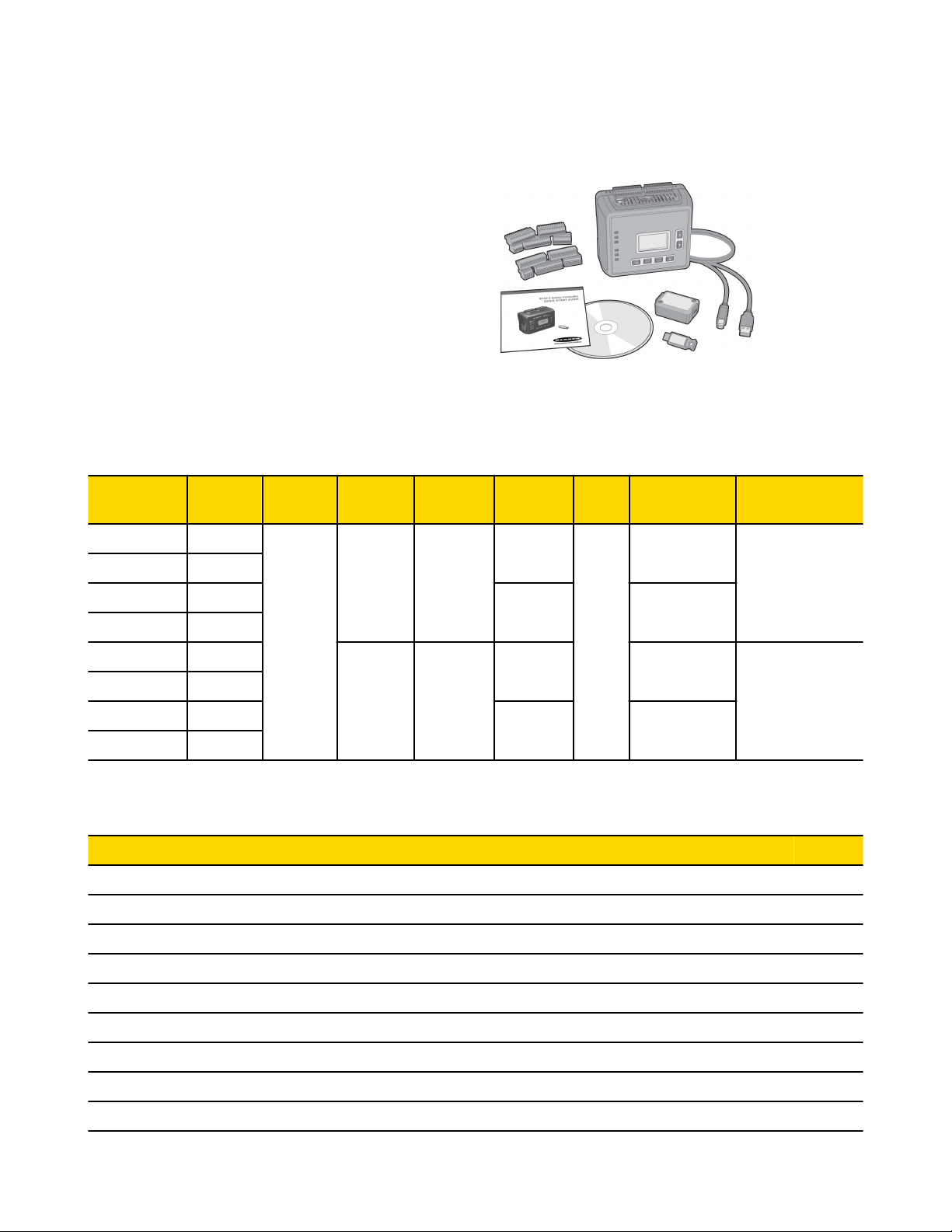
The Safety Controller Starter Kit includes:
• 1 Safety Controller (model SC22-3 or SC22-3E)
• 1 set of removable terminals (choose screw or clamp type)
• 1 SC-XM1 external memory (XM) card
• 1 USB A/B cable (Ethernet models)
• 1 SC-XMP XM card programming tool (some models)
• 1 CD containing PCI software, instruction manual, and configuration tutorials (p/n 134534)
• 1 Quick Start Guide
Ethernet connection cables (for model SC22-3E) are user-supplied.
2.4.1 PC System Requirements
Operating system: Microsoft Windows® XP, Windows 2000, Vista®, Windows 7
10 www.bannerengineering.com - tel: 763-544-3164 P/N 133487 rev. C
Page 11
SC22-3/-3E Safety Controller Instruction Manual
Hard drive space: 100 MB (plus up to 280 MB for Microsoft .NET 2.0, if not already installed)
Third-party software: Microsoft .NET 2.0, included and installed with PCI, if not already on computer Adobe® Reader® for Windows
version 7.0 or newer
USB port: USB 1.1 or 2.0 type A port
2.4.2 USB Connections
The Safety Controller is connected to a PC by way of a USB A/B cable. The cable is also used to connect the PC to the SC-XMP
programming tool, in order to download a configuration to the XM card.
Figure 2. USB connections: PC to SC-XMP programming tool
connection
Figure 3. USB connections: PC to Safety Controller USB port
connection
2.4.3 Ethernet Connections
Ethernet connections are made using an ethernet cable
from the SC22-3E Ethernet port to a network switch or the
user’s control device. The SC22-3E supports use of either
standard or crossover-style cables. Shielded cable may be
needed in high-noise environments.
Figure 4. Safety Controller external memory card (XM card) and
Ethernet (some models) connections
Legend
1 USB port
2 XM card port
3 Ethernet port
2.4.4 SC-XMP Programming Tool
The programming tool is a handy device that can be used to transfer a configuration from a PC (running the PCI software) to an XM card
or from an XM card to the PC, without requiring a Safety Controller. It connects to the PC via the USB A/B cable and the PC’s USB port.
2.4.5 SC-XM1 External Memory (XM) Card
The model SC-XM1 external memory (XM) card is a removable memory module that can store or be used to transfer a single configuration. The XM card has a write-on label on its reverse side where a configuration name or a machine identification can be noted.
P/N 133487 rev. C www.bannerengineering.com - tel: 763-544-3164 11
Page 12

The XM card can be used to:
• Keep a backup copy of the Safety Controller’s configuration (to minimize downtime in the case of a hardware failure that may require
a Controller replacement).
• Transfer configurations from one Safety Controller to another Safety Controller.
• Send (download) identical configurations into multiple Safety Controllers.
• Transfer configurations between the Safety Controller and a personal computer.
Store a configuration on the XM card in one of two ways:
• Send a copy to the XM card using the PC Interface (PCI) and the SC-XMP programming tool.
• Send a copy from the Controller to the XM card, using the Onboard Interface (OBI).
NOTES:
1. A configuration can be stored permanently in an XM card, if the “lock” function is performed. However, once the card is locked, it
cannot be unlocked (it becomes "read-only").
2. Configurations on an XM card do NOT contain any network settings. The PCI software must be used to change network settings.
SC22-3/-3E Safety Controller Instruction Manual
2.5 Configuring the Safety Controller
Building a configuration for the Safety Controller is a simple process, using one of two interfaces: the push buttons and display on the
Controller itself (the Onboard Interface, or OBI) or the PCI software program included on the enclosed CD (p/n 134534). The process
comprises three main steps:
1. Define the safeguarding application (risk assessment).
• Determine the required devices.
• Determine the required level of safety.
2. Build the configuration.
• Select safety input device types and circuit connections.
• Map each input to one or more Safety Outputs, or to other input devices.
• Set optional Safety Output ON- or OFF-time delays.
• Select non-safety input device types and circuit connections, if needed.
• Assign Status Output signals, if needed.
• Create configuration name, file name, date, and author name.
3. Confirm the configuration.
• Controller verifies that the desired configuration is valid.
• User confirms that the configuration is what is expected.
2.5.1 Onboard Interface (OBI)
The Safety Controller can be configured using its built-in push buttons and LCD screen, the Onboard Interface (OBI). The LCD display
provides I/O device and system status information for any event that causes one or more of the Safety Outputs to turn OFF. The display
is used in conjunction with the six push buttons to:
• Create or modify password-protected configurations,
• Retrieve fault log information,
• Review device wiring detail and I/O logic relationships,
• Display I/O device fault details and likely remedial steps, and
• Display configuration checksum.
NOTES:
1. Onboard Interface functions are covered in more detail in Section 5 and the OBI tutorial, located separately on the disk.
2. The OBI cannot be used to change network settings; the PCI must be used for that function.
12 www.bannerengineering.com - tel: 763-544-3164 P/N 133487 rev. C
Page 13
SC22-3/-3E Safety Controller Instruction Manual
Legend:
1. Moves cursor to the left or selects settings.
2. Moves cursor to the pre-established point in the program to re-establish
a menu reference point.
3. Enters/stores the item highlighted in the display as the intended selection
or toggles a setting.
4. Moves cursor to the right or selects settings.
5. Moves cursor down or moves through a list to display individual list
items. Also used to select settings.
6. Moves cursor up or moves through a list to display individual list items.
Also used to select settings.
7. Ethernet connector indicators (Yellow and Green; Ethernet models only)
8. Status indicators
9. LCD display
Figure 5. Onboard Interface, including push buttons, LCD display and status indicators (model SC22-3E shown)
Status Indicator Condition Indicates Controller Status
All Indicators OFF — Initiation Mode
Power
Status (Controller Mode)
USB or Tx/Rx (depending on model)
Safety Output SO1, SO2, SO3
Ethernet Connector (model SC22-3E
only)
ON Green Power ON
OFF Power OFF
ON Red Configuration mode
Flashing Red Lockout mode
OFF Run mode
Flashing Green
Transmitting or receiving data (a link is established with the PC)
OFF Not transmitting or receiving data
ON Green Safety Output ON
ON Red Safety Output OFF
Flashing Red Safety Output fault detected
Flashing Green Safety Output waiting for reset
Yellow OFF No link
Yellow ON Link OK
Green OFF No activity
Green ON or flashing Activity detected
P/N 133487 rev. C www.bannerengineering.com - tel: 763-544-3164 13
Page 14
SC22-3/-3E Safety Controller Instruction Manual
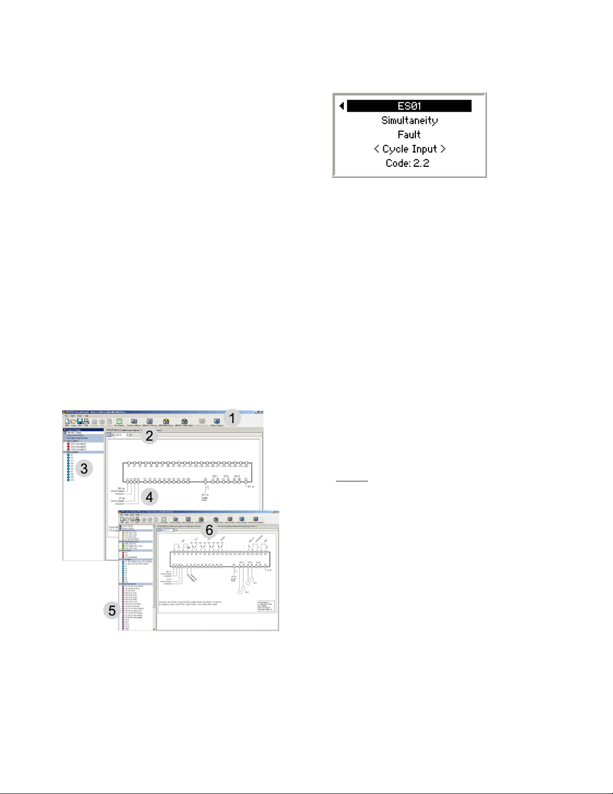
Accessing Fault Codes
Fault codes are displayed in the last line of the OBI fault diagnostics
menu (see example at right). Refer to OBI Configuration and Troubleshooting sections for more information.
2.5.2 Personal Computer Interface (PCI)
The Safety Controller can also be configured using a Windows®-based computer and the Safety Controller PC Interface (PCI) program.
This user-friendly interface makes use of icons and circuit symbols to simplify the selection of device properties during configuration. The
configuration wiring and ladder logic diagrams develop automatically as the configuration progresses.
Creating a configuration is simple. Once a configuration is created, it::
• Can be stored to a computer file for archiving and future use, or
• Can be emailed to a remote location as an attachment, or
• Can be sent directly to another Safety Controller or to the plug-in external memory card.
The PCI can be used to create a configuration, save it and send it as described above, and also monitor the function of a Controller using
the live display, as well as monitor the fault log for troubleshooting purposes.
To access the Ethernet functionality of the model SC22-3E, click on the Network Settings icon and check the Enable Network Interface
box. The Virtual Status Outputs will appear on the I/O Properties menu, as will additional tabs above the document section of the screen,
as shown in the following figure.
Legend:
1. Toolbar
2. Network settings
3. I/O properties
4. Document (in this case, Wiring Diagram)
5. Virtual Status Outputs (These outputs become
visible after the Enable Network Interface box is
checked under the Network Settings tab.)
6. New tab selections also become visible.
Figure 6. PC User Interface (PCI) main screens
• PC Interface functions are covered in more detail in section 5.1 PC Interface (PCI) Overview on page 53 and in the PCI tutorial.
• PC Interface network functions are covered in more detail in sections 4.9 Virtual Status Outputs on page 52 and 11 Ethernet Refer-
ence on page 124.
14 www.bannerengineering.com - tel: 763-544-3164 P/N 133487 rev. C
Page 15

SC22-3/-3E Safety Controller Instruction Manual
PCI Software Compatibility
To identify the version of your PCI software (i.e., PC Interface), click on the "Help" tab located on the top tool bar and then click on
"Compatibility Information." The information contained in the pop-up window identifies what PCI software version is running and lists
when a feature was added or changed.
Newer PCI versions are backwards compatible with earlier SC22 firmware versions, although features must be supported by the SC22
firmware version or the feature will be unavailable. If an unsupported feature is attempted to be downloaded, an error message will be
displayed. The SC22 firmware version can be identified via the Onboard Interface (OBI) "Model #" menu item; see section 7.3 Display
Controller Information — Onboard Interface (OBI) on page 71. This screen identifies the Safety Controller model, the firmware versions
of microprocessors A and B, and the hardware version. Contact a Banner Applications Engineer with any questions.
2.6 Input and Output Connections
2.6.1 Safety and Non-Safety Input Devices
The Safety Controller has 22 input terminals that can be used to monitor either safety or non-safety devices; these devices may incorporate either solid-state or contact-based outputs. Each of these 22 input terminals can either monitor an input signal or provide 24V dc.
The function of each input circuit depends on the type of device connected to it; this function is established when the Controller is configured.
For general and specific information about input devices, their requirements, hookup options and appropriate warnings and cautions,
additional installation information (e.g., Safety Distance), refer to the sections 4 System Installation on page 26 and 10 Input Device and
Safety Category Reference on page 90, which contains hookup information and other useful information about integrating the following
devices:
• Safety Circuit Integrity
• Protective (Safety) Stop
• Optical Sensors
• Safety Gate (Interlock Guard)
• Two-Hand Control
• Safety Mat (Edges)
• Emergency Stop Push Buttons
• Rope (Cable) Pull
• Enabling Devices (Pendants)
• Bypass
• Muting
For further information about connecting any devices to the Safety Controller, contact Banner Engineering.
Safety Device Hookup Considerations
The Safety Controller inputs can be configured to interface with many types of safety devices, including safeguarding devices (e.g., safety
light curtains), complementary protective equipment (e.g., emergency stop push buttons), and other devices that impact the safe use of a
machine (e.g., equipment protection).
The way these devices interconnect impacts their ability to exclude or detect faults that could result in the loss of the safety function.
There are many standards, regulations and specifications that require certain capabilities of a safety circuit.
WARNING: . . . User Responsibility
The user is responsible for ensuring that all local, state, and national laws, rules, codes, and regulations relating to
the use of this product in any particular application are satisfied. Extreme care is urged that all legal requirements have
been met and that all installation, operation, and maintenance instructions contained in the product documentation are followed.
P/N 133487 rev. C www.bannerengineering.com - tel: 763-544-3164 15
Page 16
SC22-3/-3E Safety Controller Instruction Manual
2.6.2 Safety Outputs
The Safety Outputs are designed to control final switching devices (FSDs) and machine primary control elements (MPCEs) that are the
last in the control chain to control the dangerous motion. These control elements include relays, contactors, solenoid valves, motor controls and other devices that incorporate force-guided (mechanically-linked) monitoring contacts, or control-reliable signals needed for external device monitoring.
The Safety Controller has three independently controlled and redundant solid-state Safety Outputs. The Controller’s self-checking algorithm ensures that the outputs turn ON and OFF at the appropriate times, in response to the assigned input signals and the system’s selfchecking test signals.
The Safety Outputs, SO1, SO2 and SO3, can be controlled by input devices with both automatic and manual reset operation.
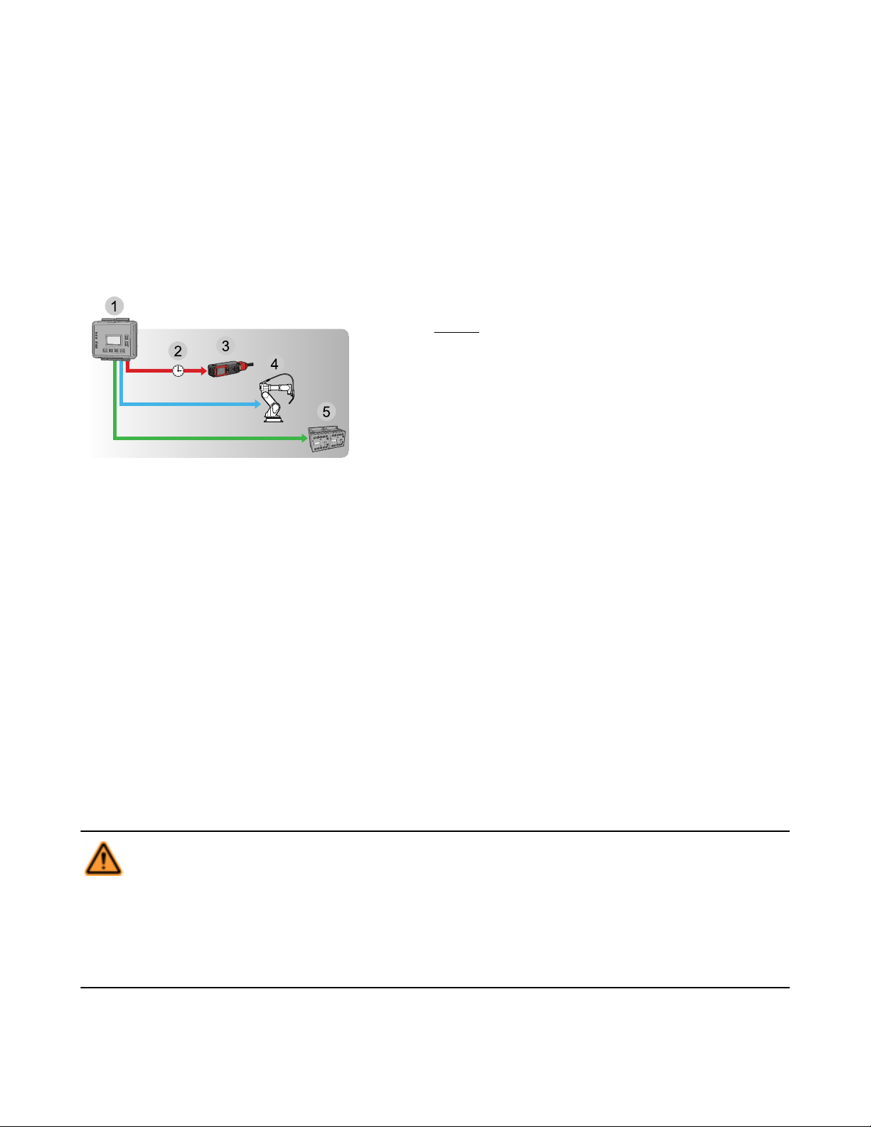
Legend:
1. Safety Controller
2. OFF-Delay
3. Solenoid locking switch
4. Robot
5. Contactors
Figure 7. Safety Outputs
See section 4.7.2 Safety Outputs on page 41 for more information about configuring Safety Outputs.
Functional Stops per IEC 60204-1 and ANSI NFPA79
The Controller is capable of performing the two functional stop types:
• Category 0: an uncontrolled stop with the immediate removal of power from the guarded machine
• Category 1: a controlled stop with a delay before power is removed from the guarded machine
Delayed stops can be used in applications where, for example, machines need power for a braking mechanism to stop the hazardous
motion.
ON-Delays and OFF-Delays
Each Safety Output can be configured to function with a time delay. There are two types of time delays: ON-delay and OFF-delay, where
the outputs turn ON or OFF only after the time limit has elapsed. The ON and OFF time delay limit options are from 100 milliseconds to 5
minutes, in 100 millisecond increments.
Safety Output ON-delays are sometimes used when a machine operation must be delayed before a safe machine startup is permitted. An
example application would be a robot weld cell.
WARNING: . . . Turning a Delayed Output ON/OFF
If an input that is mapped to both an immediate Safety Output and a delayed Safety Output opens and then closes
before the delay time of the delayed output has expired, the immediate Safety Output will turn OFF and remain OFF
while the delay time is running.
At the end of the delay time, the delayed output will also turn OFF. Both outputs will then remain OFF for about 500 ms,
before they will turn back ON. This will happen either automatically, if configured for auto reset, or after a valid manual reset
signal, if configured for manual reset.
16 www.bannerengineering.com - tel: 763-544-3164 P/N 133487 rev. C
Page 17

SC22-3/-3E Safety Controller Instruction Manual
2.6.3 Status Outputs
The Safety Controller has 10 configurable Status Outputs, used to send non-safety status signals to programmable logic controllers
(PLCs) or to human machine interfaces (HMIs), or they may be used to power indicator lights. These outputs can be configured to report
on the status of input devices, Safety Outputs, or the Controller itself. See section 4.8.1 Status Output Signal Conventions on page 50
for more information.
Signal Convention
The Status Output signal convention can be configured to be 24V dc or 0V dc to indicate:
• When an input is in the Run state,
• When a Safety Output is in the ON state (see Note 1),
• When a Safety Output is in a logical ON state (ON or in an ON-delay; see Note 1),
• When the system is in a Lockout condition,
• When an I/O fault is present (see Note 2),
• When a system reset is needed,
• When a Safety Output needs a reset (see Note 3),
• When a Safety Input is muted,
• Which Safety Input, of a defined group of Safety Inputs, turned OFF first,
• When a Safety Input is bypassed,
• When a Safety Input has a Fault condition, or
• When a Safety Output's OFF-delay can be cancelled.
NOTES:
1. Only Safety Outputs that have inputs mapped to them can be mapped to a Status Output.
2. An I/O fault is a failure of one or more Safety Inputs, Safety Outputs, or Status Outputs.
3. Only Safety Outputs mapped to inputs configured with manual reset logic can have a Status Output configured to indicate a reset is
needed.
WARNING: . . . Status Outputs
The Status Outputs are not Safety Outputs and can fail in either the ON or OFF state. They must never be used to control
any safety-critical applications. If a Status Output is used to control a safety-critical application, a failure to danger
is possible and could lead to serious injury or death.
Monitored Mute Lamp Outputs
Status Outputs O9 and O10 can be configured to create a monitored mute lamp function for a mute operation. When the mute lamp is
ON, the Controller monitors for a short circuit in the load. When the lamp is OFF, it monitors for an open circuit in the load. If an open
circuit occurs before the start of a mute cycle, the next mute cycle will be prevented. If an open circuit occurs during a mute cycle, that
mute cycle will finish, but the next mute cycle will be prevented. If a short occurs before or during a mute, that mute cycle will start and
finish, but the next mute cycle will be prevented. If not used to monitor a mute lamp, these outputs may be used in the same ways as
outputs O1–O8.
IMPORTANT: Only terminals O9 and O10 have the extra monitoring circuitry needed for a monitored mute lamp. If monitoring of
the mute lamp is not required (depending on applicable standards), any of the Status Outputs (O1–O10) may be used to indicate a mute
condition. Because of this feature, these Status Outputs will always appear ON with no load (see Specifications on page 23).
2.6.4 Virtual Status Outputs
Using the PCI, the model SC22-3E (only) can configure up to 32 Virtual Status Outputs. These outputs can communicate the same
information as the Status Outputs, but over a network.
P/N 133487 rev. C www.bannerengineering.com - tel: 763-544-3164 17
Page 18

SC22-3/-3E Safety Controller Instruction Manual
WARNING: . . . Virtual Status Outputs
The Virtual Status Outputs are not Safety Outputs and can fail in either the ON or the OFF state. They must never be used
to control any safety-critical applications. If a Virtual Status Output is used to control a safety-critical application, a
failure to danger is possible and could lead to serious injury or death.
2.6.5 I/O Mapping: the I/O Control Relationship
The term “map” implies a control logic relationship between an input and an output or between an input and another input, where the
state of the first input determines the state of the output or of the second input.
Inputs Mapped to Outputs. The following devices can be mapped directly
to the Safety Outputs:
• Emergency stop buttons
• Safety gate switches
• Optical sensors
• Two-hand control devices
• Safety mats
• Protective stop switches
• Rope pulls
Inputs Mapped to Inputs. Muting sensors and bypass switches work in conjunction with certain safety input devices to temporarily suspend the Stop signal of a safety input device. These sensors and switches are mapped directly to the safety inputs; they are then indirectly mapped to the Safety Output(s) that the muted safety inputs control (see section 4.6.4 Mute Function on page 37).
• Enabling devices
• External device monitoring
• ON/OFF devices
• Manual reset devices
• Solenoid or press safety valves
• Cancel OFF-delay devices
Figure 8. Input and Output mapping
2.7 System Settings
The Controller’s system settings define parameters for both the configuration file and the Controller. These settings include:
• Configuration name
• Author’s name
• Power-up mode
• Mute on power-up enable
• Monitored system reset
Configuration Name
The configuration name identifies the configuration that will be used in a Safety Controller application. The configuration name can be
displayed on the Controller and will be useful to be sure that the configuration in a Controller is the correct one.
Author’s Name
The author’s name may also be helpful when questions arise about configuration settings.
Power-Up Mode (Operational Characteristics When Power Is Applied)
The Controller provides three power-up mode types to choose from, to determine how the Controller will behave just after power is supplied. These modes are: Normal, Automatic, and Manual.
• Normal Power-Up Mode (default). In normal power-up mode, after power is applied:
• Only those Safety Outputs that have automatic reset inputs will turn ON.
• Safety Outputs that have one or more manual reset inputs will turn ON only after a manual (latch) reset operation is performed.
• Exception: Two-hand control inputs, bypass inputs, and enabling device inputs must be seen to be in the Stop state at power-up,
regardless of the power-up mode selection. If these are seen to be in the Run state at power-up, the outputs will remain OFF.
• Automatic Power-Up Mode. In automatic power-up mode, after power is applied:
18 www.bannerengineering.com - tel: 763-544-3164 P/N 133487 rev. C
Page 19
SC22-3/-3E Safety Controller Instruction Manual
• All Safety Outputs will turn ON immediately if the inputs that are mapped to these outputs are all in the Run state.
• Exception: Two-hand control inputs, bypass inputs, and enabling device inputs must be seen to be in the Stop state at power-up,
regardless of the power-up mode selection. If these are seen to be in the Run state at power-up, the outputs will remain OFF.
• Manual Power-up Mode. In Manual Power-up Mode, after power is applied:
• Safety Outputs will turn ON only after all inputs mapped to this output are in the Run state and a System Reset has been performed. (A manual latch reset is not required.)
• Exception: Two-hand control inputs, bypass inputs, and enabling device inputs must be seen to be in the Stop state at power-up,
regardless of the power-up mode selection. If these are seen to be in the Run state at power up, the outputs will remain OFF.
WARNING: . . . Automatic Power-Up
When the Controller is configured for automatic system reset power-up mode, the Controller acts as if all input devices are
configured for auto (trip) reset. Each Safety Output will immediately turn on at power-up if the assigned input devices
are all in the Run state, even if one or more of the input devices is configured for manual (latch) reset. If the application requires that a manual (latch) reset operation be performed before the Safety Output turns ON, then either manual or
normal power-up mode configuration must be used. Failure to do so could cause a machine to operate in an unexpected
way at power-up or after temporary power interruptions.
WARNING: . . . Controller Operation on Power-Up
It is the responsibility of the user of the Controller to assess what safeguarding devices and methods are appropriate for
any given machine or application. The Qualified Person who configures, installs, and/or maintains it must be aware of
the power-up behavior of the Controller and instruct the machine operator on the operation of the Controller and its
associated devices.
Mute On Power-Up Enable
If configured, the Mute on Power-Up function will initiate a mute cycle after power is applied to the Safety Controller if the muted safety
inputs are active (Run state or closed), and either M1-M2 or M3-M4 (but not all four) are signaling a muted condition (e.g., active or
closed).
• For more information on the Mute On Power-Up function, see section 4.6.4 Mute Function on page 37.
Monitored System Reset
Monitored System Reset is enabled by default and requires an OFF-ON-OFF signal at the reset input, where the ON-duration must be
between 0.3 and 2 seconds (trailing edge reset), in order to reset the system.
If unchecked (Monitored System Reset disabled), the reset input requires only a signal from OFF to ON (leading edge reset), in order to
reset the system.
2.8 Internal Logic
The Controller’s internal logic is designed so that a Safety Output can turn ON only if all the controlling input device signals are in the Run
state and the Controller’s self-check signals are in the No-Fault state.
Safety Input 1 Safety Input 2 Safety Controller Safety Output 1
Stop Stop Run (No Fault) OFF
Stop Run Run (No Fault) OFF
Run Stop Run (No Fault) OFF
Run Run Run (No Fault) ON
The table above illustrates the logic for two safety input devices mapped to control Safety Output 1. If any of the safety input devices are
in the Stop state, then Safety Output 1 is OFF. When both safety inputs are in the Run state, then Safety Output 1 will turn ON.
P/N 133487 rev. C www.bannerengineering.com - tel: 763-544-3164 19
Page 20

SC22-3/-3E Safety Controller Instruction Manual
2.8.1 Additional Logic Functions
Other logic functions are slight variations of the general AND logic rule set.
• Two-Hand Control: The machine initiation signal incorporating a 0.5 second actuator simultaneity limit and anti-tie-down logic, designed to prevent single-actuator machine cycle operation.
• Safety Device Muting: The automatic suspension of one or more safety input Stop signals during a portion of a machine operation
when no hazard is present or when access to the hazard is otherwise safeguarded.
• Safety Device Bypass: The manually activated, temporary suspension of one or more safety input Stop signals when the hazard is
otherwise safeguarded.
• Enabling Device Control: The actively controlled manual suspension of a Stop signal during a portion of a machine operation when
a hazard could occur.
• Cancel OFF-Delay: The option to cancel a configured OFF-delay time by either keeping the Safety Output ON, or turning it OFF
immediately.
The rules that apply to these special cases are explained in section 10 Input Device and Safety Category Reference on page 90.
2.9 Password Overview
To provide security, the Safety Controller requires use of a password in some cases. For information about changing a Controller’s password, refer to sections 5.1.4.6 Changing the Password Using the Personal Computer Interface (PCI) on page 61 and 6.3.4 System
Options on page 66. If the password becomes lost, contact the Factory for assistance.
Creating a Configuration
• Via computer using the Safety Controller PC Interface (PCI) program (no password needed)
• Via the Controller Onboard Interface (OBI) (password needed)
Confirming a Configuration
• Via the PCI, using the PC connected to a powered Controller (password needed)
• Via the OBI, on a powered Controller (password needed)
Sending a Confirmed Configuration to the Controller
• Via a direct connection between the PC and the Controller, using the SC-USB1 cable and the PC Interface program (password needed)
• Via the PC, the XM card programming tool, and the XM card (password needed)
2.10 Confirming a Configuration
Although a Controller will accept an unconfirmed configuration, it will only activate it (adopt the configuration and function according to its
parameters) after the configuration is confirmed, using the OBI or PCI.
IMPORTANT: If any modification is made to a confirmed configuration, or if a configuration is edited during the confirmation
process, the PCI and the Controller will recognize this modified configuration as being new and will require it to be confirmed
before it can be activated and used.
Once confirmed, a configuration can be stored and reused without reconfirmation. The configuration code will be validated automatically
each time it is downloaded to a Controller and whenever the Controller powers up. Configurations, confirmed or not, can be sent via
email. Sending (downloading) a new confirmed configuration to a Controller requires entry of the Controller password.
20 www.bannerengineering.com - tel: 763-544-3164 P/N 133487 rev. C
Page 21
3 Components and Specifications
To order the Safety Controller ready for use, order it as part of a kit
(see following table). It also can be ordered alone, without terminals,
as a replacement part.
Kits include the Safety Controller, model SC22-3 or SC22-3E, a set of
plug-on terminal blocks (screw or cage-clamp type, depending on
model), a USB A/B cable (for direct connection between a PC and the
Safety Controller, included with some kits), external non-volatile memory card (XM card, with write-on label on reverse side), XM card programming tool (included with some models), a user CD (includes software interface, online manual, ethernet references and configuration
tutorials), and quick start guide.
3.1 Safety Controller Starter Kit Models
Kit Model
SC22-3-S Screw
SC22-3-C Clamp
SC22-3-SU1 Screw
SC22-3-CU1 Clamp
SC22-3E-S Screw
SC22-3E-C Clamp
SC22-3E-SU1 Screw
SC22-3E-CU1 Clamp
Terminal
Type
Safety
Outputs
6 PNP
Terminals
(3 pairs)
Status
Outputs
10 Status
10 Status
plus
32 Virtual
Status
Safety Out-
put Rating
0.75 amps
each output
0.5 amps
each output
3.2 Replacement Parts/Accessories
Model Description
SC22-3 Replacement Controller (no terminals)
SC22-3E Replacement Controller (no terminals), Ethernet compatible
SC-XM1 External memory card (XM card)
USB A/B
Cable
─
1.8 m Yes
─ ─
1.8 m Yes
XM
Card
Yes
XM Card Pro-
gramming Tool
Communication
Protocol
─
─
EtherNet/IP &
Modbus/TCP
SC-XM1-5 Bulk pack of 5 XM cards
SC-XMP USB programming tool for XM card
SC-TS1 Screw terminal replacement set
SC-TC1 Cage clamp terminal replacement set
SC-USB1 USB A/B cable, 1.8 m
134534 CD including PCI program and instruction manual
P/N 133487 rev. C www.bannerengineering.com - tel: 763-544-3164 21
Page 22

SC22-3/-3E Safety Controller Instruction Manual
3.3 Ethernet Cordsets
Shielded Models Cat5e Crossover Models Length
STP07 STPX07 2.1 m
STP25 STPX25 7.6 m
STP50 STPX50 15.5 m
STP75 STPX75 23 m
3.4 Interface Modules
SC-IM9 series interface modules are for use only with the Safety Controller; dry contacts for use with higher ac/dc voltage and current.
With 10A output, DIN-mount housing, removable (plug-in) terminal blocks for OSSD outputs (screw terminal block supplied). Measures
approx. 72 mm H, 170 mm D, and 45 mm , 90 mm, or 140 mm W, (2.8" H, 6.7" D, and 1.8", 3.5", or 5.5" W) depending on model. See
datasheet p/n 131845 for more information.
NOTE: External device monitoring (EDM) is required to be wired separately to the N.C. contacts to comply with ISO 13849-1
categories and ANSI/OSHA control reliability; see section 4.7.1 External Device Monitoring (EDM) on page 40.
Model Description
SC-IM9A
SC-IM9B
SC-IM9C
IM-T-9 series interface modules have 6A output, 22.5 mm DIN-mount housing, removable (plug-in) terminal blocks. Low current rating of
1V ac/dc @ 5 mA, high current rating of 250V ac/dc @ 6A. See datasheet p/n 62822 for more information.
NOTE: External device monitoring (EDM) is required to be wired separately to the N.C. contacts to comply with ISO 13849-1
categories and ANSI/OSHA control reliability; see section 4.7.1 External Device Monitoring (EDM) on page 40.
Model Supply Voltage Inputs Safety Outputs Output Rating EDM Contacts Aux. Outputs
IM-T-9A
IM-T-11A 2 N.O. 1 N.C.
For use with 1 Safety
Controller Safety Output
For use with 2 Safety
Controller Safety Outputs
For use with 3 Safety
Controller Safety Outputs
24V dc
Supply
Voltage
24V dc
(Controller
supplied)
2 (dual-channel
hookup)
Inputs (Safety
Controller Outputs)
2
(SO1)
4
(SO1 and SO2)
6
(SO1, SO2, and SO3)
3 N.O.
Safety Outputs
3 N.O.
Total of 6
(3 N.O. per output)
Total of 9
(3 N.O. per output)
6 amps 2 N.C.
Output
Rating
10 amps
EDM Con-
tacts
1 N.C. pair per
output
—
3.4.1 Mechanically Linked Contactors
Provides an additional 10 or 16 amp carrying capability to any safety system. If used, two contactors per Safety Output pair (e.g., 2 x
SO1), are required. The N.C. contacts are to be used in an external device monitoring (EDM) circuit.
NOTE: External device monitoring (EDM) is required to be wired separately to the N.C. contacts to comply with ISO 13849-1
categories and ANSI/OSHA control reliability; see section 4.7.1 External Device Monitoring (EDM) on page 40.
22 www.bannerengineering.com - tel: 763-544-3164 P/N 133487 rev. C
Page 23

SC22-3/-3E Safety Controller Instruction Manual
Model Supply Voltage Inputs Outputs Output Rating
11-BG00-31-D024
24V dc 2 (dual-channel hookup) 3 N.O. and 1 N.C.
11-BF18C01-024 18 amps
10 amps
3.5 Specifications
Power
24V dc, ± 20%
Model SC22-3: 0.4 A (Controller only), 5.9 A (all outputs ON @ full rated load)
Model SC22-3E: 0.4 A (Controller only), 4.9 A (all outputs ON @ full rated load)
The Controller should be connected only to a SELV (safety extra-low voltage, for circuits without earth ground) or a
PELV (protected extra-low voltage, for circuits with earth ground) power supply.
Safety and Non-Safety Inputs (22 terminals)
Input ON threshold: > 15V dc (guaranteed on), 30V dc max.
Input OFF threshold: < 5V dc (guaranteed off with any 1 fault), –3V dc min.
Input ON current: 8 mA typical @ 24Vdc, > 2 mA (guaranteed with 1 fault)
50 mA peak contact cleaning current @ 24V dc
Sourcing current: 30 mA minimum continuous (3V dc max. drop)
Input lead resistance: 300 Ω max. (150 Ω per lead)
Input requirements for a 4-wire safety mat:
• Max. capacity between plates: 0.5 µF
• Max. capacity between bottom plate and ground: 0.5 µF
• Max. resistance between the 2 input terminals of one plate: 20 Ω
Safety Outputs (6 terminals, 3 redundant outputs)
Rated output current:
Model SC22-3: 0.75 A max. @ 24V dc (1.0V dc max. drop)
Model SC22-3E: 0.5 A max. @ 24V dc (1.0V dc max. drop)
Output OFF threshold: 0.6V dc typical (1.2V dc max. guaranteed with 1 fault)
Output leakage current: 50 µA max. with open 0V
Load: 0.1 µF max., 1 H max., 10 Ω max. per lead
Status Outputs (10 terminals)
Rated output current: 0.5A @ 24V dc (individual), 1.0 A @ 24V dc (total of all outputs)
O1 to O8 (General Purpose)—Output OFF voltage: < 0.5V dc (no load), 22 KΩ pull down to 0V
O9 and O10 (General Purpose or Monitored Mute Lamp)—
Output OFF voltage: Internal 94 KΩ pull up to 24V dc supply
Output ON/OFF threshold: 15V dc +/−4V dc @ 24V dc supply
NOTE: For O9 and O10 (when configured as a monitored mute lamp output), if a short circuit or other fault condition causes the output to drop below this threshold while the output is ON, a lockout will occur. If an open circuit or
other fault condition causes the output to rise above this threshold while the output is OFF, a lockout will occur.
Response and Recovery Times
Response Time (ON to OFF): 10 ms max. (with standard 6 ms debounce; this can increase if debounce time increases.
Refer to the configuration summary for actual response time.)
P/N 133487 rev. C www.bannerengineering.com - tel: 763-544-3164 23
Page 24

SC22-3/-3E Safety Controller Instruction Manual
Recovery Time (OFF to ON): 400 ms max. (with manual reset option)
Recovery Time (OFF to ON): 400 ms max. plus input debounce time (auto reset)
Onboard LCD Information Display—Password Requirements
Password is not required:
Run mode (I/O status)
Fault (I/O fault detection and remedial steps)
Review configuration parameters (I/O properties and terminals)
Password is required:
Configuration mode (create/modify/confirm/download configurations)
Environmental Rating
NEMA 1 (IEC IP20), for use inside NEMA 3 (IEC IP54) or better enclosure
Operating Conditions
Temperature range: 0° to +55° C (+32° to 131° F)
Mechanical Stress
Shock: 15g for 11 milliseconds, half sine, 18 shocks total (per IEC 61131-2)
Bump: 10g for 16 milliseconds, 6000 cycles total (per IEC 61496-1)
Vibration: 3.5 mm occasional / 1.75 mm continuous @ 5Hz to 9Hz, 1.0g occasional and 0.5g continuous @ 9Hz to 150Hz:
(per IEC 61131-2) and 0.35 mm single amplitude / 0.70 mm peak-to-peak @ 10 to 55Hz (per IEC 61496-1), all @ 10 sweep
cycles per axis
EMC
Meets or exceeds all EMC requirements in IEC 61131-2, IEC 61496-1 (Type 4), and IEC 62061 Annex E, Table E.1 (increased immunity levels)
Removable Terminals
Screw terminals
Wire sizes: 16, 18, 20, 22 or 24 AWG (0.20 – 1.31 mm²)
Wire strip length: 5.00 mm (0.197")
Tightening torque: 0.23 Nm (2 in. lbs.) nominal; 0.34 Nm (3.0 in. lbs.) maximum
Clamp terminals
Important: Clamp terminals are designed for 1 wire only. If more than 1 wire is connected to a terminal, a wire could
loosen or become completely disconnected from the terminal, causing a short.
Wire size: 16, 18, 20, 22, or 24 AWG (0.20 – 1.31 mm²)
Wire strip length: 9.00 mm (0.35")
Network Interface (Model SC22-3E only)
Ethernet 10/100 Base-T/TX, RJ45 modular connector
Selectable auto negotiate or manual rate and duplex
Auto MDI/MDIX (auto cross)
Protocols: EtherNet/IP (with PCCC), Modbus/TCP
Data: 32 configurable virtual Status Outputs; fault diagnostic codes and messages; access to fault log
Product Performance Standards
IEC 62061 Safety of Machinery – Functional Safety of Safety-Related Electrical, Electronic and Programmable Electronic
Control Systems: SIL CL 3
IEC 61508 Functional Safety of Electrical/Electronic/Programmable Electronic Safety-Related Systems: SIL 3
ISO 13849-1 (1999): Category 4
24 www.bannerengineering.com - tel: 763-544-3164 P/N 133487 rev. C
Page 25

64 mm
(2.5")
131 mm
(5.2")
112 mm
(4.4")
130 mm
(5.1")
35 mm
(1.4")
Allow minimum 65 mm (2.6") clearance
for USB cable or Ethernet cable and
43 mm (1.7") for XM Card insertion
SC22-3/-3E Safety Controller Instruction Manual
ISO 13849-1 (2006): Category 4 Performance Level (PL) e, complies with Machinery Directive 2006/42/EC
IEC 61131-2 Programmable Controllers, Part 2: Equipment Requirements and Tests
UL 508 Industrial Control Equipment
UL 1998 Software in Programmable Components
ANSI NFPA 79 Electrical Standards for Industrial Machinery
IEC 60204-1 Electrical Equipment of Machines: General Requirements
ISO 13851 (EN574) Safety of Machinery – Two-Hand Control Devices – Functional Aspects and Design Principles
ISO 13850 (EN418) Emergency Stop Devices
Also see front section of this manual for a list of other applicable U.S. and international standards.
Agency Approvals
3.5.1 Dimensions
Figure 9. SC22-3 and SC22-3E dimensions
P/N 133487 rev. C www.bannerengineering.com - tel: 763-544-3164 25
Page 26
SC22-3/-3E Safety Controller Instruction Manual
4 System Installation
4.1 Appropriate Application
The correct application of the Safety Controller is dependent on the type of machine and the safeguards that are to be interfaced with the
Controller. The Controller is generally interfaced with safeguards that may be used only on machinery that is capable of stopping motion
immediately upon receiving a stop signal and at any point in its machine cycle. It is the user’s responsibility to verify whether the safeguarding is appropriate for the application and is installed as instructed by the appropriate installation manuals. If there is any doubt
about whether or not your machinery is compatible with this Controller, contact a Banner Applications Engineer.
WARNING: . . . Not a Stand-Alone Device
This Safety Controller is not a stand-alone point-of-operation guarding device, as defined by OSHA regulations. It is
necessary to install point-of-operation guarding devices, such as safety light screens and/or hard guards, to protect personnel
from hazardous machinery. Failure to install point-of-operation guards on hazardous machinery can result in a dan-
gerous condition which could lead to serious injury or death.
WARNING: . . . User Is Responsible for Safe Application of this Product
The application examples described in this document depict generalized guarding situations. Every guarding applica-
tion has a unique set of requirements.
Extreme care is urged to ensure that all legal requirements are met and that all installation instructions are followed.
Direct any questions regarding safeguarding to a factory applications engineer at the number or addresses listed in the back
of this document.
WARNING: . . . Shock Hazard and Hazardous Energy
Always disconnect power from the safety system (e.g., device, module, interfacing, etc.) and the machine being controlled before making any connections or replacing any component.
Electrical installation and wiring must be made by Qualified Personnel and must comply with the relevant electrical standards
and wiring codes, such as the NEC (National Electrical Code), ANSI NFPA79, or IEC 60204-1, and all applicable local standards and codes.
Lockout/tagout procedures may be required. Refer to OSHA 29CFR1910.147, ANSI Z244-1, or the appropriate standard
for controlling hazardous energy.
WARNING: . . . Read this Section Carefully Before Installing the System
The Banner Safety Controller is an accessory device that is typically used in conjunction with a machine safeguarding device.
Its ability to perform this function depends upon the appropriateness of the application and upon the Safety Controller’s proper mechanical and electrical installation and interfacing to the machine to be guarded.
If all mounting, installation, interfacing, and checkout procedures are not followed properly, the Safety Controller
cannot provide the protection for which it was designed. The user has the responsibility to ensure that all local, state,
and national laws, rules, codes, or regulations relating to the installation and use of this control system in any particular application are satisfied. Extreme care should be taken to ensure that all legal requirements have been met and that all technical
installation and maintenance instructions contained in this manual are followed. Read Section 3 (and its subsections) of
this manual carefully before installing the system. Failure to follow these instructions could result in serious bodily
injury or death.
26 www.bannerengineering.com - tel: 763-544-3164 P/N 133487 rev. C
Page 27

SC22-3/-3E Safety Controller Instruction Manual
The user has the sole responsibility to ensure that this Safety Controller is installed and interfaced to the guarded machine by
Qualified Persons (see Glossary), in accordance with this manual and applicable safety regulations.
4.2 Installing the Safety Controller
The Safety Controller mounts to a standard 35 mm DIN-rail track. It must be installed inside an enclosure rated NEMA 3 (IEC IP54) or
better. It can be mounted in any orientation. The user must comply with all instructions contained within product manuals and relevant
regulations.
For reliable operation, the user must ensure that the operating specifications are not exceeded. The enclosure must provide adequate
heat dissipation, so that the air closely surrounding the Controller does not exceed its maximum operating temperature. Methods to reduce heat build-up include venting, forced air flow (e.g., exhaust fans), adequate enclosure exterior surface area, and spacing between
the Safety Controller and other sources of heat. (See Specifications, “Operating Conditions” on page 24.)
Mount the Safety Controller in a convenient location that is free from heavy impulse force and high-amplitude vibration.
Electrostatic Discharge (ESD) can cause damage to electronic equipment. To prevent this, follow proper ESD handling practices such as:
• Wear an approved wrist strap or other approved grounding products.
• Touch a grounded object before handling the Controller.
See ANSI/ESD S20.20 for further information about managing ESD.
4.3 Safety Input Devices
Safety input devices allow for the cessation of motion, or an otherwise hazardous situation, by controlling the Safety Outputs of the Safety
Controller. A Safety Output in the OFF state results in a stop of motion and removal of power from the machine actuators (assuming this
does not create additional hazards).
For a Safety Output to turn ON, all of its controlling safety input devices must be in their Run state. A few special safety input device
functions can, under predefined circumstances, temporarily suspend the safety input “stop signal” to keep the Safety Output ON (e.g.,
muting and bypassing).
The Safety Controller input configurations, depending on the type, have means to detect failures and faults that would otherwise result in
a loss of that control of the safety function. Once such a failure or fault is detected, the Safety Controller will lock out until the problem is
fixed.
Other input configurations do not have this detection capability. It is recommended that in all circumstances the installation of the Safety
Controller and its associated safety and safeguarding devices be installed to eliminate or minimize the possibility of failures and faults
that could result in the loss of the safety function(s).
Methods to eliminate or minimize the possibility of these failures include, but are not limited to:
• Physically separating interconnecting control wires from each other and from secondary sources of power.
• Routing interconnecting control wires in separate conduit, runs, or channels.
• Locating all elements (modules, switches, and devices under control) within one control panel, adjacent to each other, and directly
connected with short wires.
• Properly installing multi-conductor cabling and multiple wires through strain-relief fittings. (Over-tightening of a strain-relief can cause
short circuits at that point.)
• Using positive-opening or direct-opening components, as described by IEC 60947-5-1 that are installed and mounted in a positive
mode.
• Periodically checking the functional integrity / safety function and training the the operators, maintenance personnel, and others with
the operation of the machine and the safeguarding, and to recognize and immediately correct all failures.
Follow the device manufacturer's installation, operation, and maintenance instructions and all relevant regulations. If there
is any question about the device(s) that are connected to the Safety Controller, contact a Banner Application Engineer for
assistance.
P/N 133487 rev. C www.bannerengineering.com - tel: 763-544-3164 27
Page 28
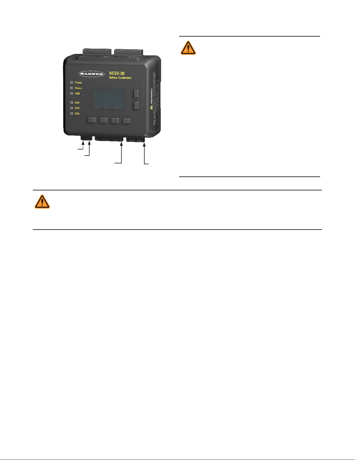
SO1 SO2 SO3
Safety
Outputs
Inputs
S1.............S11
2 x 24V dc (A1)
Inputs
S12...........S22
2 x 0V dc (A2)
0V dc (A2)
O1.........O10
Status
Outputs
System Reset (SR)
SC22-3/-3E Safety Controller Instruction Manual
Figure 10. Input and output terminal locations
WARNING: . . . Sharing of Safety Inputs
Multiple Safety Controllers must not share safety input devices; this includes solid-state outputs
from light curtains, Safety Controllers, or other safety devices. A Safety Output from one Controller can
be connected to a Safety Input of a second Controller. However, the second Controller should be
the only device to which the output from the first
Controller is connected.
If a third device is also connected to the same Safety Output (now used as the safety input of the second Controller): during a power transition of the second Controller, the input may be a source of current,
momentarily causing a false ON (Run) signal at the
input of the third device. Failure to connect multi-
ple Controllers correctly could create an unsafe
condition that may lead to serious bodily injury
or death.
WARNING: . . . Failures and Faults
The Safety Controller Safety control can be interfaced with input devices at differing levels of integrity, as described in Appendix A. The user must conduct a Risk Assessment to determine the appropriate level of integration. The user also must
eliminate or minimize the possibility of failures and faults that could result in the loss of the safety function(s).
4.3.1 Signals: Run and Stop States
Dual-channel safety input devices have two separate signal lines. Dual-channel signals for some devices are both positive (+24V dc)
when the device is in the Run state. Others have a complementary circuit structure where one channel is at 24V dc and the other is at 0V
dc when the device is in the Run state. For the sake of clarity, instead of referring to a safety input device as being “ON” (e.g., 24V dc) or
“OFF” (e.g., 0V dc), this manual adopts the Run state/Stop state convention.
4.3.2 Safety Input Device Properties
The Controller can be configured to accommodate many types of safety input devices. However, a number of device properties must be
established (using either the OBI or PCI interface) so that the Controller can properly monitor their signals. These configurable properties
include:
• Device name—This is generated automatically by the Controller and can be changed by the user.
• Circuit type—The circuit and signal convention options that can be selected to define the input device.
• Reset logic—Automatic (Trip mode) or Manual (Latch mode).
• Terminal number—The assignment of input terminals for a device.
• I/O mapping—The logic control relationship between inputs and outputs or between inputs.
• Signal change-of-state—Simultaneous or Concurrent type, and signal convention (high or low)
• Signal debounce time—The signal state transition time.
• Start-up test—An optional precautionary safety input device test required after each power-up.
• Function time limit—The adjustable time limit within which a function is allowed to operate.
• Muteable—Whether or not the device can be muted.
• Bypassable—Whether or not the device can be bypassed.
28 www.bannerengineering.com - tel: 763-544-3164 P/N 133487 rev. C
Page 29
E-Stop Safety
Gate
Optical
Sensor
Two-Hand
Control
Rope
Pull
Protect.
Stop
Safety
Mat
Enabling
Device
Mute
Sensors
Bypass
Switch
EDM AVM
Circuit
Types
7 13 10 7 10 10 1 10 7 10 2
Reset
Logic
Auto/
Manual
Auto/
Manual
Auto/
Manual
Auto
Auto/
Manual
Auto/
Manual
Auto/
Manual
Auto Auto Auto — —
—
I/O
Mapping
I/O I/O I/O I/O I/O I/O I/O I/O I/I I/I I/O
2
I/O
Signal
COS*
S/C S/C S/C S S/C S/C — S/C S S/C S
Debounce
Times
Yes Yes Yes Yes Yes Yes Yes Yes Yes Yes No No
Start Up
Test
— Yes Yes — — — — — — — —
Function
Time Limit
— — — — — — Yes Yes Yes Yes—
Muteable — Yes Yes Yes — YesYes — — — —
Bypassable — Yes Yes Yes — Yes Yes — — — —
—
—
—
* Refer to change-of-state table.
S = Simultaneous
C = Concurrent
SC22-3/-3E Safety Controller Instruction Manual
Circuit Types: Contact and Solid State Circuits
The table below depicts many of the input devices and circuit types the Controller can monitor. It highlights which of these properties can
be configured, and for which devices. More description of some of these topics is included in the following paragraphs.
Not all circuit types meet the Category 4 classification per ISO 13849-1; refer to section 10.1 Safety Circuit Integrity and ISO
13849-1 (EN954-1) Safety Circuit Principles on page 90 for a discussion of safety circuit integrity levels.
Reset Logic: Manual or Automatic Reset
Safety input devices can be configured to require a manual reset before the Safety Output(s) they control are permitted to turn back ON.
This is sometimes referred to as “latch” mode because the Safety Output “latches” to the OFF state until a reset is performed. If a safety
input device is configured for automatic reset or “trip” mode, the Safety Output(s) it controls will turn back ON when the input device
changes to the Run state (provided that all other controlling inputs are also in the Run state).
Reset rules and types are discussed in section 4.5 Input Device Resets on page 33.
Terminal Numbers: Connecting the Input Devices
The Controller needs to know what device signal lines are to be connected to which wiring terminals, so that it can apply the proper signal
monitoring methods, Run and Stop convention, timing rules, and fault rules. Although terminals are assigned automatically during the
configuration process, the terminal assignments can be changed manually, using either the Onboard Interface or the PC Interface.
P/N 133487 rev. C www.bannerengineering.com - tel: 763-544-3164 29
Page 30
2 Terminals 3 Terminals 2 Terminals, PNP
24V
OFFON
2-Ch, 2 Terminal
PNP
2-Ch, 2 Terminals 2-Ch, 3 Terminals 2-Ch, 4 Terminals
24V
ONON
4 Terminals 5 Terminals
PNP
24V
OFFON OFFON
2-Ch, 2 Terminals
SC22-3/-3E Safety Controller Instruction Manual
Signal Change-of-State Types
Two change-of-state (COS) types can be used when monitoring dual-channel safety input device signals: Simultaneous or Concurrent.
The rules for each circuit type are shown in the table below.
Input Circuit
Input Signal COS Timing Rules
Stop State—SO turns OFF when¹: Run State—SO turns ON when²:
Dual-Channel A and B Complementary At least 1 channel (A or B) input is in
the Stop state.
Dual-Channel A and B
2X Complementary A and B At least 1 channel (A or B) is within a
pair of contacts in the Stop state.
Simultaneous. A and B are both in the
Stop state and then both in the Run
state within 3 seconds before outputs
turn ON.
Concurrent. A and B concurrently in
the Stop state, then both in the Run
state with no simultaneity, to turn outputs ON.
Simultaneous. A and B concurrently in
the Stop state, then contacts within a
channel in the Run state within 400 ms
(150 ms for 2-hand control), both channels in the Run state within 3 seconds
(0.5 seconds for 2-hand control)
Concurrent. A and B concurrently in
the Stop state, then contacts within a
channel in the Run state within 3 seconds. Both channels in the Run state
with no simultaneity.
¹ Safety Outputs turn OFF when one of the controlling inputs is in the Stop state.
² Safety Outputs turn ON only when all of the controlling inputs are in the Run state and after a manual reset is performed (if any safety
inputs are configured for Manual reset and were in their Stop state).
Signal Debounce Times
Closed-to-Open Debounce Time (from 6 to 100 milliseconds in 1 ms intervals, except 6 to 1,500 ms for mute sensors). The
closed-to-open debounce time is the time limit required for the input signal to transition from the high (24V dc) state to the steady low (0V
dc) state. This time limit may need to be increased in cases where high-magnitude device vibration, impact shock, or switch noise conditions result in longer signal transition times. If the debounce time is set too short under these harsh conditions, the system may detect a
signal disparity fault and lock out. (Default setting is 6 ms.)
Dual-Channel Safety Mat
• Input channels are shorted together (normal operation), or
• At least 1 of the wires is disconnected, or
• One of the normally low channels
is detected high, or
• One of the normally high channels
is detected low.
Each channel detects its own pulses.
30 www.bannerengineering.com - tel: 763-544-3164 P/N 133487 rev. C
Page 31

SC22-3/-3E Safety Controller Instruction Manual
CAUTION: . . . Debounce and Response
Any changes in the closed-to-open debounce time will affect the Safety Output response (turn OFF) time. This value
is computed and displayed for each Safety Output when a configuration is created. The values are also listed in the OBI and
the PCI Configuration Summary documents. (Default setting is 6 ms.)
Open-to-Closed Debounce Time (from 10 to 500 milliseconds in 1 ms intervals, except 10 to 1,500 ms for mute sensors). The
open-to-closed debounce time is the time limit required for the input signal to transition from the low (0V dc) state to the steady high (24V
dc) state. This time limit may need to be increased in cases where high magnitude device vibration, impact shock, or switch noise conditions result in longer signal transition times. If the debounce time is set too short under these harsh conditions, the system may detect a
signal disparity fault and lock out. (Default setting is 50 ms.)
When a safety mat is used, the response time calculation for the safety mat is dependent on the Stop (6 to 100 ms) debounce time.
CAUTION: . . . Response Times
• The response time for a complementary device is based on the closed contact(s) opening, not on the open con-
tact(s) closing. Both will lead to a stop signal, but only one determines the response time.
• Any changes in the open-to-closed debounce time will affect the Safety Output reaction (turn ON) time!
• The configurable debounce of an ON/OFF input and an enabling device input are not part of the calculated and confirmed
response times.
4.4 Non-Safety Input Devices
The non-safety input devices include manual reset devices, ON/OFF switches, and mute enable devices.
Configurable Properties Manual Reset ON/OFF Mute Enable Cancel OFF-Delay
Circuit Types 3 3 3 3
Input and Output Mapping I/O I/O I/I I/O
Closed-to-open:
Debounce Times Fixed at 50 ms
Monitored / Non-monitored Yes — — Yes
Manual Reset Devices. The manual reset is used to create a reset signal after a safety input device that has been configured to require
a manual reset has been opened and closed. After the manual reset operation is performed, any of the Safety Outputs controlled by that
safety input device can turn ON.
WARNING: . . . Non-Monitored Resets
If a non-monitored reset (either latch or system reset) is configured and if all other conditions for a reset are in place, a
short from the Reset terminal to +24V will turn ON the Safety Output(s) immediately.
6-100 ms
Open-to-closed:
10-500 ms
Fixed at 50 ms Fixed at 50 ms
ON/OFF Switch. The ON/OFF switch is used to provide a machine ON or OFF command. When all of the controlling safety inputs are in
the Run state, this function permits the Safety Output to turn ON and OFF. This is a single-channel signal; the Run state is 24V dc and
the Stop state is 0V dc. An ON/OFF input can be added without mapping to a Safety Output, which allows this input to control only a
Status Output.
Mute Enable Switch. The mute enable switch is used to signal the Controller when the mute sensors are permitted to perform a mute
function. When the mute enable function is configured, the mute sensors will not be enabled to perform a mute function until the mute
enable signal is in the Run state. This is a single-channel signal; the enable (Run) state is 24V dc and the disable (Stop) state is 0V dc.
P/N 133487 rev. C www.bannerengineering.com - tel: 763-544-3164 31
Page 32

Safety Input(s)
(Manual or Auto)
Cancel Delay Input
(Monitored Option Shown)
Safety Output
(Cancel Off Delay)
Status Output
(OK to Cancel OFF-Delay)
Off Delay
Started
Off Delay
Ended
Run
Stop
Run
Reset
Active
Inactive
ON
OFF
Off Delay
Normal End
Cancel Delay
Performed
Off Delay
0.5 sec.
2
2
1
1
Note 1 - If “turn output off” function is selected
Note 2 - If “keep output on” function is selected
Safety Input(s)
(Manual or Auto)
Cancel Delay Input
(Monitored Option Shown)
Safety Output
(Cancel Off Delay)
Status Output
(OK to Cancel OFF-Delay)
Off Delay
Started
Off Delay
Ended
Run
Stop
Run
Reset
Active
Inactive
ON
OFF
Off Delay
Normal End
On (Auto)
Off (Manual)
Cancel Delay
Performed
Off Delay
0.5 sec.
SC22-3/-3E Safety Controller Instruction Manual
Cancel OFF-Delay Devices. This feature provides the option to cancel a configured OFF-delay time. It functions in one of two ways:
• Keeps the Safety Output ON, or
• Turns the Safety Output OFF immediately, after the Controller receives a Cancel OFF-Delay signal.
A new Status Output (O.K. to Cancel Output's OFF-Delay Status) will indicate when a Cancel Delay Input can be activated, in order to
keep the OFF-delayed Safety Output ON.
Figure 11. Cancel Delay Timing: Safety Input remains in Stop mode
Figure 12. Cancel OFF-Delay Timing: "Turn Output OFF" function
32 www.bannerengineering.com - tel: 763-544-3164 P/N 133487 rev. C
Page 33

Manual Safety Input(s)
Latch Reset Input
(Monitored Reset Shown)
Cancel Delay Input
(Monitored Option Shown)
Safety Output
Status Output
(OK to Cancel OFF-Delay)
Off Delay
Started
Off Delay
Ended
Run
Stop
Run
Reset
Active
Inactive
ON
OFF
Off Delay
Normal End
Cancel Delay
Performed
Off Delay
Run
Reset
Latch Reset
Performed
Auto Safety Input(s)
Cancel Delay Input
(Monitored Option Shown)
Safety Output
Status Output
(OK to Cancel OFF-Delay)
Off Delay
Started
Off Delay
Ended
Run
Stop
Run
Reset
Active
Inactive
ON
OFF
Off Delay
Normal End
Cancel Delay
Performed
Off Delay
SC22-3/-3E Safety Controller Instruction Manual
Figure 13. Cancel OFF-Delay Timing: "Keep Output ON" function, manual (latch) Safety Input
Figure 14. Cancel OFF-Delay Timing: "Keep Output ON" function, auto (trip) Safety Input
4.5 Input Device Resets
Three reset types are available:
• Manual Reset: used to manually reset a Safety Output that has turned OFF in response to a Stop signal from safety input device
configured for manual ("Latch mode") reset. The reset signal type can be configured to be either monitored or non-monitored (the
default setting is monitored).
• System Reset: used to recover from a fault condition or to restart the Controller after a new configuration has been altered. This
reset device (a button or switch) connects to a dedicated input terminal on the Safety Controller, labeled SR. The reset signal type
can be configured to be either monitored or non-monitored (the default setting is
• Automatic Reset: used to allow a Safety Output to return to an ON state without action by an individual once the input device
changes to the RUN state (provided that all other controlling inputs are also in the Run state). Also known as "Trip mode," automatic
reset is typically used in applications in which the individual continually is being sensed by the safety input device.
The reset switch must be mounted at a location that complies with the warning below. A key-actuated reset switch provides some
operator or supervisory control, as the key can be removed from the switch and taken into the guarded area. However, this does not
prevent unauthorized or inadvertent resets due to spare keys in the possession of others, or additional personnel entering the guarded
P/N 133487 rev. C www.bannerengineering.com - tel: 763-544-3164 33
monitored).
Page 34

Safety Device 1
(Auto)
Safety Device 2
(Manual)
Manual Monitored
Reset Input
Safety Output
area unnoticed (a "pass-through hazard"). See section 4.5.3 Perimeter Guarding and Pass-Through Hazards on page 35 for more informaton.
Resetting a safeguard must not initiate hazardous motion. Safe work procedures require a start-up procedure to be followed and the
individual performing the reset to verify that the entire hazardous area is clear of all personnel, before each reset of the safeguard is
performed. If any area can not be observed from the reset switch location, additional supplemental safeguarding must be used: at a
minimum, visual and audible warnings of machine start-up.
SC22-3/-3E Safety Controller Instruction Manual
WARNING: . . . Reset Switch Location
All reset switches must be accessible only from outside, and in full view of, the hazardous area. Reset switches
must also be out of reach from within the safeguarded space, and must be protected against unauthorized or inadvertent operation (e.g., through the use of rings or guards). If any areas are not visible from the reset switch(es), additional
means of safeguarding must be provided. Failure to do so could result in serious bodily injury or death.
4.5.1 Reset Signal Requirements
Both manual (latch) reset and system reset signals can be configured for monitored or non-monitored operation, as follows:
Monitored resets—Requires the reset signal to transition from low (0V dc) to high (24V dc) and then back to low. The high state duration
must be 0.3 to 2 seconds. This is said to be a “trailing edge trip event.”
Non-monitored resets—Requires only that the reset signal transitions from low (0V dc) to high (24V dc) and stays high for at least 0.3
seconds. After the reset, the reset signal can be either high or low. This is said to be a “leading-edge trip event.”
4.5.2 Automatic and Manual Reset Inputs Mapped to the Same Safety Output
Safety input devices can be configured for either manual (Latch mode) or automatic (Trip mode) reset and both types can be mapped to
the same Safety Output. In order for a Safety Output to turn ON, all associated safety input devices must be in their Run state. If one or
more of these safety input devices is configured for manual reset and one or more of them change from the Stop state to the Run state,
then the output will need a valid manual reset signal before it will turn ON.
If two safety inputs, each configured for manual reset, are mapped to the same Safety Output, then only one valid reset operation is
required to reset the Safety Output. A manual reset operation is valid when all safety inputs mapped to the Safety Output are in the Run
state and the manual reset is performed. If a manual reset is performed before a safety input is in the Run state, the manual reset signal
is ignored (except in the case of a two-hand control and an ON/OFF input).
See sections 7.4 Manual Reset on page 73 and 7.5 System Resets and Lockout Conditions on page 74 for more information about
resets.
Figure 15. Timing logic: auto and manual monitored reset safety inputs mapped to the same Safety Output (no delay)
34 www.bannerengineering.com - tel: 763-544-3164 P/N 133487 rev. C
Page 35

Safety Device 1
Manual Monitored Reset
Safety Device 2
Manual Monitored Reset
Manual Reset
Safety Output
SC22-3/-3E Safety Controller Instruction Manual
Figure 16. Timing logic: Safety Outputs with a common reset, mapped to the same Safety Output
4.5.3 Perimeter Guarding and Pass-Through Hazards
A "pass-through hazard" is associated with applications, such as perimeter guarding, where personnel may pass through a safeguard
(which issues a stop command to remove the hazard), and then continue into the guarded area, where their presence is no longer detected. The related danger becomes the unexpected start or restart of the machine while personnel are within the guarded area.
Reducing or Eliminating Pass-Through Hazards
Eliminate or reduce pass-through hazards whenever possible. While it is recommended to eliminate the pass-through hazard altogether,
this may not be possible due to machine layout, machine capabilities, or other application considerations.
• One solution is to ensure that personnel are continually sensed while within the hazardous area. This can be accomplished by
using supplemental safeguarding, such as described by the ANSI B11 series of safety requirements or other appropriate standards.
• An alternate method is to ensure that when the safeguarding device is tripped, it will latch (manual reset), and will require a
deliberate manual action to reset. This method of safeguarding relies upon the location of the reset switch as well as safe work practices and procedures to prevent an unexpected start or restart of the guarded machine.
WARNING: . . . Perimeter Guarding Applications
If the application could result in a pass-through hazard (e.g., perimeter guarding), either the safeguarding device or
the guarded machine's MSCs/MPCEs must cause a Latched response following a Stop command (e.g., interruption
of the sensing field of a light curtain, or opening of an interlocked gate/guard). The reset of this Latched condition may
only be achieved by actuating a reset switch that is separate from the normal means of machine cycle initiation. The switch
must be positioned as described in this document.
Lockout/Tagout procedures per ANSI Z244.1 may be required, or additional safeguarding, as described by ANSI B11
safety requirements or other appropriate standards, must be used if a passthrough hazard can not be eliminated or reduced
to an acceptable level of risk. Failure to observe this warning could result in serious bodily injury or death.
4.6 Safety Input Function
4.6.1 Internal Logic
The Controller’s internal logic is designed so that a Safety Output can turn
ON only if all the controlling safety input device signals and the Controller’s
self-check signals are in the Run state and report that there is no fault condition.
The table at right illustrates the logic for two safety input devices that are
mapped to control Safety Output 1. If either safety input device is in the
Stop state, the Safety Output will be OFF. When both safety inputs and the
Controller are in the Run state, Safety Output 1 will be ON.
Safety Input 1 Safety Input 2 Safety Output 1
Stop Stop OFF
Stop Run OFF
Run Stop OFF
Run Run ON
P/N 133487 rev. C www.bannerengineering.com - tel: 763-544-3164 35
Page 36

Two-Hand
Control Device
Safety Device 2
(Manual Reset)
Reset Signal
Safety Output
SC22-3/-3E Safety Controller Instruction Manual
4.6.2 Two-Hand Control (THC)
The two-hand control function requires that two hand actuators (e.g., hand/palm buttons) each be activated within 0.5 seconds of each
other in order to produce a Run signal to start a machine cycle. THC devices are always the last input (in time) to turn the Safety Output
ON. If one or more of the other controlling input devices are configured for manual reset and are used to stop the machine, a manual
reset must be performed before the THC device can cycle the machine again.
See section 10.5 Two-Hand Control on page 100 for more information.
Figure 17. Timing logic: two-hand control device and manual reset safety input device
Two-Hand Control Activation on Power-Up Protection. The Controller’s two-hand control logic will not permit the assigned Safety
Output to turn ON when power is initially supplied while the THC actuators are in their Run state. The THC actuators must change to their
Stop state and return to the Run state before the Safety Output can turn ON.
A two-hand control device does not have a manual reset option.
4.6.3 Enabling Devices
The enabling device actively controls the suspension of a Stop signal during a portion of a machine operation where a hazard can occur.
The enabling device permits a hazardous portion of the machine to run, but must not start it. A separate machine command signal from
another device is needed to start hazardous motion. This enabling device must have ultimate hazard turn OFF or Stop authority
when being used. The enabling device is sometimes referred to as the “live man pendant.”
An enabling device can be mapped to one or more Safety Outputs. When the enable signal goes from the Stop state to the Run state, the
Controller will go into Enable mode. In this mode, the associated Safety Outputs will turn ON if any of the assigned EDM inputs are
closed (these may open after the outputs turn ON) and all of the controlling E-stop or rope pull devices are in their Run state. With the
exception of the E-stop and rope pull devices, all other safety input signals (Run or Stop) will be ignored while the Controller is in Enable
mode. Safety Output enabling control resides in the enabling device function when in Enable mode. Repetitive enable cycles are allowed.
In order to exit Enable mode, the enabling device must be in the OFF state, and a system reset must be performed.
Enabling Device Time Limit. The enabling device time limit can be adjusted between 1 second and 30 minutes and cannot be disabled.
When the time limit expires, the associated Safety Outputs will turn OFF. In order to start a new Enable mode cycle with the time limit
reset set to its original time limit value, the enabling device must switch from ON to OFF, and back to ON.
All ON- and OFF-delay times associated with the Safety Outputs that are controlled by the enabling device function will be honored
during the Enable mode.
36 www.bannerengineering.com - tel: 763-544-3164 P/N 133487 rev. C
Page 37

Enable Device
Safety Device
Safety Output
(ON-Delayed)
System Reset
Enable Mode
ON-
Delay
ON-
Delay
ON-
Delay
ON-
Delay
ON-
Delay
ON-
Delay
Don’t Care*Don’t Care*Don’t Care*
Enable
Mode ON
Enable
Mode ON
Enable
Mode ON
*Unless it’s an E-Stop or a Rope-Pull*Unless it’s an E-Stop or a Rope-Pull*Unless it’s an E-Stop or a Rope-Pull
Enable
Mode OFF
Enable
Mode OFF
Enable
Mode OFF
Mute
Enable
ON or OFF
Safety
Input
Mute Sensor
Pair
Safety
Output
SC22-3/-3E Safety Controller Instruction Manual
Figure 18. Timing logic: Enabling device and enable mode
See section 10.9 Enabling Device on page 112 for more information.
4.6.4 Mute Function
Safety device muting is the automatically controlled suspension of one or more safety input stop signals during a portion of a machine
operation when no immediate hazard is present or when access to the hazard is safeguarded. Muting sensors can be mapped to one or
more of the following “mutable” safety input devices:
• Safety gate (interlocking) switches
• Optical sensors
• Two-hand controls
• Safety mats
• Protective stops
(E-stop buttons, rope pulls, enabling devices, external device monitoring, and bypass switches are said to be “non-mutable” devices or
functions.)
At least two mute sensors are required for each muting operation (the mute occurs typically 100 ms after the second mute sensor input
has been satisfied). One or two pairs of mute sensors can be mapped to one or more safety input devices so that their assigned Safety
Outputs can remain ON to complete the operation; see section 10.11 Mute Sensor Pair on page 116 for more information.
Mute Enable. The optional mute enable function can be configured to ensure that a mute function is permitted only at the appropriate
time. If a mute enable input device has been mapped to a mutable safety input device, this safety input device can be muted only if the
mute enable switch is in the Enable (24V dc) state at the time the mute cycle is started. After the mute cycle starts, the ME input can be
turned OFF. A mute enable input device can be mapped to one or more mutable safety inputs.
NOTE: Mute enable is not a safeguarding function, but rather a machine logic function.
Figure 19. Timing logic: one mute sensor pair with mute enable
Mute Time Limit (Backdoor Timer). A time limit can be established to limit how long a mute cycle is permitted to be active. The time
limit can be adjusted from 1 second to 30 minutes. A different time limit can be set for each mutable safety input device. Other input
devices that are also muted are affected only by their own mute time limit setting. The mute time limit can be disabled. When disabled,
the time limit for the mute function for that input device is infinite.
P/N 133487 rev. C www.bannerengineering.com - tel: 763-544-3164 37
Page 38

SC22-3/-3E Safety Controller Instruction Manual
Directional Muting. As soon as two mute sensor pairs are configured and mapped to a muteable Safety Input, an advanced setting
option appears in the PCI to provide the option of directional muting. Check the box "Enable Directional Muting," then select the muting
sensor pair to be blocked first. The Controller requires sensor pair 1 to be blocked first, then the safeguard, then sensor pair 2 (all within
the configured time limits) in order for the mute to take place.
Mute Sensor Debounce Time. The input debounce time, accessible under the "Advanced settings" in the Mute Sensor Pair properties
window, can be used to extend a mute cycle after a mute sensor signal is removed. By configuring the "closed-to-open" debounce time,
the mute cycle can be extended up to 1.5 seconds (1500 ms) to allow the Safety Input Device to re-energize its outputs (turn ON). The
start of the mute cycle can also be delayed, by configuring the "open-to-closed" debounce time.
Mute on Power-Up Function. If configured, the Mute on Power-Up function will initiate a mute cycle after power is applied to the Safety
Controller if the muted safety inputs are active (Run state or closed), and either M1-M2 or M3-M4 (but not all four) are signaling a muted
condition (e.g., active or closed).
WARNING: . . . Mute on Power-Up
The Mute on Power-Up function should be used only in applications where:
• Muting the System (M1 and M2 closed) when power is applied is required, and
• Using it does not, in any situation, expose personnel to any hazard.
Mute on Power-Up Disabled. When the mute on power-up option is disabled, the Controller will not go into a mute cycle, even if the
conditions for a valid mute cycle are fulfilled at power-up.
Mute on Power-Up Enabled. When the Mute on Power-Up option is enabled, the Controller will go into a mute cycle if the conditions for
a valid mute cycle are fulfilled at power-up. Specific valid mute signal conditions must be present for a mute cycle to be initiated and
maintained.
If Auto Power-Up is configured, the Controller allows approximately 2 seconds for the input devices to become active (closed) to accommodate systems that may not be immediately active at power-up. If Manual Power-Up is configured and all other conditions are satisfied,
the first valid system reset after the muted safety inputs are active (Run state or closed) will result in a mute cycle. The Mute On Power-
up function should only be used if safety can be assured when the mute cycle is expected, and the use of this function is the
result of a risk assessment and is required by that particular machine operation.
WARNING: . . . Mute and Bypass
Mute and Bypass operations must be done in a way that minimizes personnel risk. Implement the following when cre-
ating mute and bypass applications:
• Guard against unintended stop signal suspension by using one or more diverse-redundant mute sensor pairs or a
dual channel key-secured bypass switch.
• Set reasonable time limits (no longer than needed) for the mute and bypass functions.
Failure to follow these rules could lead to an unsafe condition that could result in serious injury or death.
See section 10.11 Mute Sensor Pair on page 116 for more information.
4.6.5 Bypass Function
The safety device bypass is a manually activated and temporary suspension of one or more safety input stop signals when no immediate
hazard is present. Bypass switches can be mapped to one or more of the following safety input devices:
• Safety gate (interlocking) switches
• Optical sensors
• Two-hand control devices
• Safety mats
• Protective stop
When the bypass switch signal changes to the Bypass (Run) state, it will turn ON or keep ON all the Safety Outputs that are controlled by
the bypassed safety input devices only if all other non-bypassed safety devices that are mapped to these Safety Outputs are in the Run
state.
38 www.bannerengineering.com - tel: 763-544-3164 P/N 133487 rev. C
Page 39

Light
Screen
Mute
Sensor 1 (2)
Mute
Sensor 2 (1)
Bypass
Switch
Safety
Output
BypassTime
Expired
BypassTime
Expired
BypassTime
Expired
Don’t Care
Safety Output
100 ms
to
5 sec.
100 ms
to
5 sec.
100 ms
to
5 sec.
Don’t Care Don’t Care
ON
OFF
Closed
Open
AVM
SC22-3/-3E Safety Controller Instruction Manual
Bypass Time Limit. A bypass function time limit can be established to limit how long the safety input device bypass is active. The time
limit can be adjusted from 1 second to 12 hours and cannot be disabled. Only one time limit can be set, and this limit will apply to all
safety devices that are bypassed. At the end of the time limit, Safety Output control authority is handed back to the bypassed safety input
devices.
Two-Hand Control Bypassing. If a Two-Hand Control input is actuated while the input is being bypassed, the Safety Controller will lock
out and issue a Stop signal. This ensures that the operator does not mistake that the Two-Hand Control is functional and is aware that
the bypassed Two-Hand Control is no longer providing the safeguarding function.
Mute-Dependent Override. When this option is enabled, and a mute sensor is mapped to the safety input device, and the safety input
device is in the STOP state, at least one of the Mute sensors must be in the Mute (Run) state in order to start a new bypass cycle. If the
conditions are right for bypass, the mute Status Output indicator (if configured) will start flashing at 1 Hz. If this option is disabled, the
Safety Input is not required to be in the Stop state and the mute sensors need not be blocked, in order to start a new bypass cycle.
Figure 20. Timing logic: Light screen with mute sensors and bypass switch
4.6.6 Adjustable Valve Monitoring (AVM) Function
Adjustable Valve (Device) Monitoring function is similar in function to One-Channel External Device Monitoring (1-channel EDM, see
section 4.7.1 External Device Monitoring (EDM) on page 40). The function monitors the state of the device(s) that are controlled by the
Safety Output to which the function is mapped. When the Safety Output turns OFF, the AVM input must be high/ON (+24V dc applied)
before the AVM timer expires or a lockout will occur. The AVM input must also be high/ON when the Safety Output attempts to turn ON or
a lockout will occur. See figure below; note that the 100 ms to 5 second time period is adjustable in 50 ms intervals (default is 100 ms).
Figure 21. Timing logic: AVM function
The Adjustable Valve (Device) Monitoring function is useful for dynamically monitoring devices under control of the Safety Output that
may become slow, "sticky," or fail in an energized state or position and whose operation needs to be verified after a Stop signal occurs.
Example applications include single- or dual-solenoid valves controlling clutch/brake mechanisms, and position sensors that monitor the
home ("safe") position of a linear actuator.
Synchronization or checking a maximum differential timing between two or more devices (e.g., dual valves) can be achieved by mapping
multiple AVM functions to one Safety Output and configuring the AVM timer to the same values. Any number of AVM inputs can be
mapped to one Safety Output. An input signal can be generated by a hard/relay contact or a solid-state PNP output.
P/N 133487 rev. C www.bannerengineering.com - tel: 763-544-3164 39
Page 40

SC22-3/-3E Safety Controller Instruction Manual
CAUTION: . . . Adjustable Valve Monitoring (AVM) Operation
When an input is configured with automatic reset logic and is quickly cycled (from Run to Stop to Run), the Safety Output(s)
will not turn ON until the AVM input is satisfied. This could result in an ON-delay up to the configured AVM monitoring
time.
It is the user's responsibility to ensure the AVM monitoring time is properly configured for the application and to
instruct all individuals associated with the machine about the possibility of the ON-Delay effect, which may not be
readily apparent to the machine operator or to other personnel.
4.7 EDM, OSSD (Safety Output), and FSD Hookup
4.7.1 External Device Monitoring (EDM)
The Controller’s Safety Outputs can control external relays, contactors, or other devices that have a set of normally closed (N.C.) forceguided (mechanically linked) contacts that can be used for monitoring the state of the machine power contacts. The monitoring contacts
are normally closed (N.C.) when the device is turned OFF. This capability permits the Controller to detect if the devices under load are
responding to the Safety Output, or if the N.O. contacts are possibly welded closed or stuck ON.
The EDM function provides a method to monitor these types of faults and to ensure the functional integrity of a dual-channel system,
including the MPCEs and the FSDs.
An EDM input can be mapped to only one Safety Output.
The EDM inputs can be configured in three ways: one-channel, two-channel, or no monitoring. One- and two-channel EDM are used
when the OSSD outputs directly control the de-energizing of the MPCEs or external devices.
• One-Channel Monitoring: a series connection of closed monitor contacts that are forced-guided (mechanically linked) from each
device controlled by the Controller. The monitor contacts must be closed before the Controller outputs can be reset (either manual or
automatic). After a reset is executed and the Safety Outputs (OSSDs) turn ON, the status of the monitor contacts are no longer
monitored and may change state. However, the monitor contacts must be closed within 250 milliseconds of the OSSD outputs going
from ON to OFF.
• Two-Channel Monitoring: an independent connection of closed monitor contacts that are forced-guided (mechanically linked) from
each device controlled by the Controller. Both EDM inputs must be closed before the Controller can be reset and the OSSDs can turn
ON. While the OSSDs are ON, the inputs may change state (either both open, or both closed). If the inputs remain in opposite states
for more than 250 milliseconds, a lockout will occur.
• No Monitoring: If no monitoring is desired, simply do not select either one-channel or the two-channel option. If the Controller does
not use the EDM function in category 3 or category 4 applications, the user must ensure that any single failure or accumulation of
failures of the external devices does not result in a hazardous condition and a successive machine cycle will be prevented.
CAUTION: . . . EDM Configuration
If the application does not require the EDM function, it is the user’s responsibility to ensure that this does not create a
hazardous situation.
CAUTION: . . . External Device Monitoring Hookup
It is strongly recommended that at least one normally closed, forced-guided monitoring contact of each MPCE or
external device be wired in order to monitor the state of the MPCEs (as shown in the hookup figures). If this is done,
proper operation of the MPCEs will be verified. MPCE monitoring contacts must be used in order to maintain control
reliability.
40 www.bannerengineering.com - tel: 763-544-3164 P/N 133487 rev. C
Page 41

+24V dc
MPCE 1
SO 1
MPCE1
Safety Input
Device
EDM
Safety Controller
MPCE 2
MPCE2
Single-channel EDM used to monitor both
MPCE feedback signals. If one or both chan nels do not close, the system goes into a Lockout condition.
Dual-channel EDM is used to monitor
both MPCE feedback signals. If the
channels are not in the same state,
the system goes into a Lockout condi tion.
+24V dc
MPCE 1
SO 1
MPCE1
Safety Input
Device
EDMEDM
Safety Controller
MPCE 2
MPCE2
Safety Output
250 ms
Max.
250 ms
Max.
250 ms
Max.
Don’t Care Don’t Care
ON
OFF
Closed
Open
EDM
Safety Output
250 ms
Max.
250 ms
Max.
250 ms
Max.
250 ms
Max.
250 ms
Max.
250 ms
Max.
Don’t Care
Closed
Open
Closed
Open
EDM 1
EDM 2
Safety Output
Must Match EDM 2 Must Match EDM 2
ON
OFF
Closed
Open
EDM 1
Must Match EDM 1 Must Match EDM 1
Closed
Open
EDM 2
SC22-3/-3E Safety Controller Instruction Manual
Figure 22. One-channel EDM hookup
Figure 23. Two-channel EDM hookup
Figure 24. Timing logic: One-channel EDM status, with respect to Safety Output
Figure 25. Timing logic: Two-channel EDM, timing between channels
For two-channel EDM, as shown below, both channels must be closed before the Safety Output(s) turn ON.
Figure 26. Timing logic: Two-channel EDM status, with respect to Safety Output
4.7.2 Safety Outputs
The Safety Controller has three pairs of solid-state Safety Outputs (SO1 a and b, SO2 a and b, and SO3 a and b). Each pair consists of
two output signal switching devices (OSSDs). The solid-state Safety Outputs are actively monitored to detect short circuits to the supply
voltage, to each other, and to other sources of electrical energy. If a failure is detected, the outputs will switch to an Off state. For circuits
requiring the highest level of safety and reliability, either OSSD must be capable of stopping the motion of the guarded machine controlled by a Safety Output, in an emergency.
P/N 133487 rev. C www.bannerengineering.com - tel: 763-544-3164 41
Page 42

Safety Input
SO 1
(ON-Delay)
SO 2
(OFF-Delay)
DelayDelayDelay
DelayDelayDelay
500 ms500 ms500 ms
SC22-3/-3E Safety Controller Instruction Manual
OSSD Output Connections
The output signal switching device (OSSD) outputs must be connected to the machine control such that the machine’s safety related
control system interrupts the circuit or power to the machine primary control element(s) (MPCE), resulting in a non-hazardous condition.
Final switching devices (FSDs) typically accomplish this when the Safety Outputs go to the OFF state.
Refer to the output specifications on page 23 and Warning below before making OSSD connections and interfacing the Controller to the
machine.
ON-Delays and OFF-Delays
Each Safety Output can be configured to function with either an ON-delay or an OFF-delay (see Figure below), where the output turns
ON or OFF only after the time limit has elapsed. An output cannot have both ON- and OFF-delays. The ON and OFF time delay limit
options are from 100 milliseconds to 5 minutes, in 100 millisecond increments.
Current operation is to honor the OFF-delay for internal and system faults, whenever possible.
Figure 27. Timing logic: Safety Output with OFF-delay
NOTICE: Safety Outputs are Dual-Channel.
An individual Safety Output is not, by itself, capable of meeting Category 4 applications (per ISO13849-1). When the risk assessment or
relevant regulations require high levels of safety integrity (i.e., Category 4), both the output signal switching device (OSSD) outputs
must be connected to the machine control so that the machine’s safety related control system interrupts the circuit or power to the
machine primary control element(s) (MPCEs), resulting in a non-hazardous condition.
Final switching devices (FSDs) typically accomplish this when the OSSDs go to an OFF state. See wiring diagrams.
WARNING: . . . OFF-Delays
A Safety Output OFF-delay time will be honored even if the safety input that caused the OFF-delay timer to start switches
back to the Run state before the delay time expires. However, in cases of a power interruption or a power loss, an OFF-
delay time can end immediately. If such an immediate machine stop condition could cause a potential danger, then
additional safeguarding measures must be taken to prevent injuries.
WARNING: . . . Interfacing of Both OSSDs
Both of the OSSD (Output Signal Switching Device) outputs must be connected to the machine control so that the
machine’s safety-related control system interrupts the circuit to the machine primary control element(s), resulting in a nonhazardous condition.
Never wire an intermediate device(s) (e.g., PLC, PES, or PC) that can fail in such a manner that there is the loss of
the safety stop command, OR in such a manner that the safety function can be suspended, overridden, or defeated,
unless accomplished with the same or greater degree of safety.
42 www.bannerengineering.com - tel: 763-544-3164 P/N 133487 rev. C
Page 43

SC22-3/-3E Safety Controller Instruction Manual
WARNING: . . . Safety Output Lead Resistance
In order to ensure proper operation, the resistance in the Safety Output wires should not exceed 10 ohms. A higher
resistance than 10 ohms may mask a short between the dual-channel Safety Outputs and could create an unsafe condition
that may lead to serious bodily injury or death.
4.7.3 FSD Interfacing Connections
Final switching devices (FSDs) can take many forms, though the most common are forced-guided (mechanically linked) relays or Interfacing Modules. The mechanical linkage between the contacts allows the device to be monitored by the external device monitoring circuit
for certain failures.
Dependent on the application, the use of FSDs can facilitate controlling voltage and current that differs from the OSSD outputs of the
Controller. FSDs can also be used to control an additional number of hazards by creating multiple safety stop circuits.
Safety (Protective) Stop Circuits
A safety stop allows for an orderly cessation of motion or hazardous situation for safeguarding purposes, which results in a stop of motion
and removal of power from the MPCEs (assuming this does not create additional hazards). A safety stop circuit typically comprises of a
minimum of two normally open contacts from forced-guided (mechanically linked) relays, which are monitored to detect certain failures
such that the loss of the safety function does not occur (i.e. external device monitoring). Such a circuit can be described as a “safe
switching point.”
Typically, safety stop circuits are a series connection of at least two N.O. contacts coming from two separate, positive-guided relays,
each of them controlled by one separate Safety Output of the Controller. The safety function relies on the use of redundant contacts to
control a single hazard, so that if one contact fails ON, the second contact will arrest the hazard and prevent the next cycle from occurring.
Interfacing safety stop circuits must be wired so that the safety function can not be suspended, overridden, or defeated, unless accomplished in a manner at the same or greater degree of safety as the machine’s safety-related control system that includes the Controller.
The normally open outputs from an interfacing module are a series connection of redundant contacts that form safety stop circuits and
can be used in either single-channel or dual-channel control methods. (See wiring diagrams.)
Dual-Channel Control. Dual-channel (or two-channel) control has the ability to electrically extend the safe switching point beyond the
FSD contacts. With proper monitoring (i.e., EDM), this method of interfacing is capable of detecting certain failures in the control wiring
between the safety stop circuit and the MPCEs. These failures include a short-circuit of one channel to a secondary source of energy or
voltage, or the loss of the switching action of one of the FSD outputs. The result could lead to the loss of redundancy or a complete loss
of safety if not detected and corrected.
The possibility of a wiring failure increases as the physical distance between the FSD safety stop circuits and the MPCEs increase, as the
length or the routing of the interconnecting wires increases, or if the FSD safety stop circuits and the MPCEs are located in different
enclosures. Thus, dual-channel control with EDM monitoring should be used in any installation where the FSDs are located remotely from
the MPCEs.
Single-Channel Control. Single-channel (or one-channel) control, as mentioned, uses a series connection of FSD contacts to form a
safe switching point. After this point in the machine’s safety-related control system, failures can occur that would result in the loss of the
safety function (e.g., a short-circuit to a secondary source of energy or voltage).
Thus, this method of interfacing should only be used in installations where FSD safety stop circuits and the MPCEs are physically located
within the same control panel, adjacent to each other, and are directly connected to each other; or where the possibility of such a failure
can be excluded. If this can not be achieved, then two-channel control should be used.
Methods to exclude the possibility of these failures include, but are not limited to:
• Physically separating interconnecting control wires from each other and from secondary sources of power.
• Routing interconnecting control wires in separate conduit, runs, or channels.
• Routing interconnecting control wires with low voltage or neutral that can not result in energizing the hazard.
• Locating all elements (modules, switches, devices under control, etc.) within the same control panel, adjacent to each other, and
directly connected with short wires.
P/N 133487 rev. C www.bannerengineering.com - tel: 763-544-3164 43
Page 44

SC22-3/-3E Safety Controller Instruction Manual
• Properly installing multi-conductor cabling and multiple wires that pass through strain-relief fittings. Over-tightening of a strain-relief
can cause short circuits at that point.
• Using positive-opening or direct-drive components installed and mounted in a positive mode.
WARNING: . . . Use of Transient Suppressors
Transient suppressors are recommended. They MUST be installed across the coils of the FSDs. NEVER install suppressors directly across the contacts of the FSDs. It is possible for suppressors to fail as a short circuit. If installed
directly across the contacts of the FSDs, a short-circuited suppressor will create an unsafe condition.
WARNING: . . . OSSD Interfacing
To ensure proper operation, the Safety Controller output parameters and machine input parameters must be considered when interfacing the solid-state Safety Outputs to the machine inputs. Machine control circuitry must be designed
so that:
• The maximum cable resistance value between the Safety Controller solid-state Safety Outputs and the machine inputs is
not exceeded,
• The Safety Controller’s solid-state Safety Output maximum Off state voltage does not result in an ON condition, and
• The Safety Controller’s solid-state Safety Output maximum leakage current, due to the loss of 0V, will not result in an ON
condition.
Failure to properly interface the Safety Outputs to the guarded machine could result in serious bodily injury or
death.
WARNING: . . . Shock Hazard and Hazardous Energy
Always disconnect power from the safety system (e.g., device, module, interfacing, etc.) and the machine being controlled before making any connections or replacing any component.
Electrical installation and wiring must be made by Qualified Personnel and must comply with the relevant electrical standards
and wiring codes, such as the NEC (National Electrical Code), ANSI NFPA79, or IEC 60204-1, and all applicable local standards and codes.
Lockout/tagout procedures may be required. Refer to OSHA 29CFR1910.147, ANSI Z244-1, or the appropriate standard
for controlling hazardous energy.
WARNING: . . . Proper Wiring
The generalized wiring configurations shown are provided only to illustrate the importance of proper installation.
The proper wiring of the Safety Controller to any particular machine is solely the responsibility of the installer and
end user.
44 www.bannerengineering.com - tel: 763-544-3164 P/N 133487 rev. C
Page 45

1A 1B 2A 2B 3A 3B
SO1 SO2 SO3
1A 1B
2A 2B
3A 3B
FSD
FSD
FSD
+24V dc
+24V dc
Input Terminals
Safety Controller
Safety Stop
Circuit
Single-Channel
Dual-Channel
Safety Stop
Circuit
Single-Channel
Dual-Channel
SC22-3/-3E Safety Controller Instruction Manual
Generic Hookup: 1-channel, 2-channel, and No EDM Options
The following figure is generic in nature and represents all three EDM options:
• Safety Output SO1 is shown with NO EDM configured (typically used with self-monitored devices).
• Safety Output SO2 is shown with Two-Channel EDM configured.
• Safety Output SO3 is shown with One-Channel EDM configured.
Any particular Safety Controller configuration may use any combination of external device monitoring options, depending on the application.
Figure 28. Generic hookup showing 1-channel, 2-channel, and no EDM options
P/N 133487 rev. C www.bannerengineering.com - tel: 763-544-3164 45
Page 46

MPCE
1
MPCE
2
MPCE
3
+24V dc
0V dc
SC-IM9A
Supplied
Terminal
Block
1A 1B 2A 2B 3A 3B A2
13 21 33 43 A1
14 22 34 44 A2
13 21 33 43 A1
14 22 34 44 A2
SO1 SO2 SO3
*
*
*
+24V dc
Input Terminals
Safety Controller
(To SO 1A)
(To SO 1B)
Machine Control
3 wires
* Installation of transient (arc) suppressors across the coils of MPCE1, MPCE2, and MPCE3
is recommended (see Warning)
SC22-3/-3E Safety Controller Instruction Manual
One-Channel EDM Hookup to SC-IM9A Interface Module
The SC-IM9A interface module depicted in the following figure is shown in one-channel EDM hookup. The SC-IM9B and SC-IM9C modules are connected in the same manner, using individual one-channel EDM circuits (terminals 21/22 on each pair of contactors).
Figure 29. One-channel EDM hookup to SC-IM9A interface module
46 www.bannerengineering.com - tel: 763-544-3164 P/N 133487 rev. C
Page 47

0V dc
S3
S4
Y3
Y1
13
23
33
Feedback (optional)
* Installation of transient (arc) suppressors across the coils of MPCE1 and MPCE2
is recommended (see Warning)
Y4
Y2
14
24
34
S1
S2
K2
K1
Machine
Control
MPCE
2
MPCE
1
IM-T-9A
Input Terminals
Safety Controller
*
*
1A 1B 2A 2B 3A 3B A2
SO1 SO2 SO3
+24V dc
SC22-3/-3E Safety Controller Instruction Manual
Two-Channel EDM Hookup to IM-T-9A Interface Module
The IM-T-9A interface module depicted in the following figure is shown in two-channel EDM hookup. The IM-T-11A module is connected
in a similar manner. Depending on the application, each Safety Output requires a separate and individually wired IM-T-..A module.
Figure 30. Hookup: Two-channel EDM hookup to IM-T-9A interface module
P/N 133487 rev. C www.bannerengineering.com - tel: 763-544-3164 47
Page 48

0V dc
S3
S4
Y3
Y1
13
23
33
Y4
Y2
14
24
34
S1
S2
K2 K1
MPCE
2
MPCE
1
IM-T-9A
*
*
1A 1B 2A 2B 3A 3B A2
SO1 SO2 SO3
+24V dc
Feedback (optional)
* Installation of transient (arc) suppressors across the coils of MPCE1 and MPCE2
is recommended (see Warning)
Machine
Control
Input Terminals
Safety Controller
SC22-3/-3E Safety Controller Instruction Manual
One-Channel EDM Hookup to IM-T-9A Interface Module
The IM-T-9A interface module depicted in the following figure is shown in one-channel EDM hookup. The IM-T-11A module is connected
in a similar manner.
Depending on the application, each Safety Output requires a separate and individually wired IM-T-..A module.
Figure 31. Hookup: One-channel EDM hookup to IM-T-9A interface module
48 www.bannerengineering.com - tel: 763-544-3164 P/N 133487 rev. C
Page 49

Power Supply Other
Equipment
Safety Controller
0V 0V SO1 SO2 SO324V dc 24V dc
Load
Current
6 Output Loads
RL
Other
Current
RL = Leadwire resistance
Vo = Voltage > 0.9V when a
safety output is off (or pulsing off)
may cause error codes 1.1, 1.2,
1.5
Power Supply Other
Equipment
Safety Controller
0V 0V SO1 SO2 SO324V dc 24V dc
Load
Current
6 Output Loads
Other
Current
Improved Wiring Scheme:
- Either dashed wire is OK
- Consider heavier wire
- Better: Use separate 0V return
for each pair of outputs (a+b)
when heavily loaded
1a1b2a2b3a3
b
SC22-3/-3E Safety Controller Instruction Manual
4.7.4 Common Wire Installation
To avoid nuisance lockout codes 1.1, 1.2, or 1.5, give thoughtful consideration to the leadwire resistance of the 0V common wire and to
the currents flowing in that wire. Notice the location of the block in the diagram below representing leadwire resistance (RL).
Figure 32. DC-common wire installation
When a safety output turns OFF, the voltage at the output terminal (VO ) must drop below 0.9V with respect to the 0V terminal of the
Safety Controller. If the voltage is higher than this, the Controller may think that the output is still on and lock out.
This residual voltage can occur in several ways:
• a large current flowing in a shared 0V conductor by other safety outputs that are still on,
• a common mode current flowing from other equipment, or
• either of these, along with a 0V wire that is too small, or too long.
The solution is to increase the wire gauge of the 0V common wire and/or consider using the courtesy 0V terminals on the Safety Controller as shown in the following diagram. This eliminates the influence of common mode current from other equipment.
Figure 33. DC-common wire installation: eliminating the influence of common mode current from other equipment
P/N 133487 rev. C www.bannerengineering.com - tel: 763-544-3164 49
Page 50

SC22-3/-3E Safety Controller Instruction Manual
4.8 Status Outputs
4.8.1 Status Output Signal Conventions
Two signal conventions are selectable for each Status Output. The default convention provides a 24V dc signal when the monitored input
or output is active (closed, high or ON), when the system is in a Lockout, when there is an I/O-fault, when the system waits for a Reset,
when the output waits for a reset or during an active mute cycle. If the above conditions are not true, the signal output would show 0V.
Signal convention 2 is the reverse of convention 1, as shown in the following table.
Mapped Status Output(s) State
Tracked Function
Track Input Input Run Input Stop Input Run Input Stop
24V dc 0V dc 0V dc 24V dc
Track Output Output ON Output OFF Output ON Output OFF
24V dc 0V dc 0V dc 24V dc
System Lockout Status Lockout Run Mode Lockout Run Mode
24V dc 0V dc 0V dc 24V dc
I/O Fault Fault No Fault Fault No Fault
24V dc 0V dc 0V dc 24V dc
System Waiting for Reset Reset Required Reset Not Required Reset Required Reset Not Required
24V dc 0V dc 0V dc 24V dc
Mute Status Muted No Mute Muted No Mute
24V dc 0V dc 0V dc 24V dc
Track Input Group Input That Turned OFF
First
Signal Convention 1 (default)
24V dc = Run
Other Linked Inputs Input That Turned OFF
Signal Convention 2
0V dc = Run
Other Linked Inputs
First
24V dc 0V dc 0V dc 24V dc
Bypass Status Input Bypassed Not Bypassed Input Bypassed Not Bypassed
24V dc 0V dc 0V dc 24V dc
Track Input Fault Fault No Fault Fault No Fault
24V dc 0V dc 0V dc 24V dc
OK to Cancel OFF-Delay OK Not OK OK Not OK
24V dc 0V dc 0V dc 24V dc
50 www.bannerengineering.com - tel: 763-544-3164 P/N 133487 rev. C
Page 51

SC22-3/-3E Safety Controller Instruction Manual
4.8.2 Status Output Functionality
Track Input
A Status Output configured for this function will indicate the current state of an input.
Track Output
A Status Output configured for this function will indicate the current physical state of a Safety Output, either ON or OFF.
Track Output’s Logical State
When selecting the Status Output function ‘Track output,’ an option to track the logical state, rather than the physical state, of a Safety
Output is provided. This option may be used to indicate a Safety Output has been commanded OFF, but is not OFF yet, such as during
an OFF-delay.
System Lockout Status
A Status Output configured for this function will be active when a lockout that affects the entire Safety Controller has been detected, such
as an internal memory fault.
I/O Fault Status
A Status Output configured for this function will be active when a lockout affecting a particular input or output has been detected, such as
a failed input or an EDM fault.
System Waiting for Reset
A Status Output configured for this function will be active under the following conditions:
• A system fault has occurred and all Safety Outputs are OFF.
• An EDM fault has occurred.
• An AVM fault has occurred.
• A fault on a Safety Output has occurred.
• A fault for monitoring a mute lamp has occurred.
• The Safety Controller is configured for manual reset on power-up.
• A fault on a THC input has occurred.
The following conditions involve the use of the system reset but no indication is provided by a Status Output:
• Exiting Configuration Mode
• Exiting Enable Mode
• Re-enabling a Track Input Group function of a Status Output
Output Waiting for Reset
A Status Output configured for this function will be active when a Safety Output is ready to be turned ON (a manual reset must be
performed).
Mute Status
A Status Output configured for this function will be active for a particular mutable Safety Input under the following conditions:
• ON during an active muting cycle.
• OFF during an inactive muting cycle.
• Flashing when all conditions for bypassing a mutable Safety Input (override) are present.
• ON when bypassing a mutable Safety Input.
Track Input Group
Status Outputs configured for this function will indicate which Safety Input of a defined group of Safety Inputs turned OFF first. Use a
system reset to re-enable the function after all Safety Inputs of the group are ON.
P/N 133487 rev. C www.bannerengineering.com - tel: 763-544-3164 51
Page 52

Bypass Status
Status Outputs configured for this function will indicate when an input is truly bypassed. A Safety Input is required to be determined
inactive at least once before a bypass can take place. The Status Output is active when the input is bypassed. A bypass cannot take
place (the input must be open) on power-up.
Track Input Fault
Status Outputs configured for this function will indicate any fault on an input.
OK to Cancel OFF-Delay
Status Outputs configured for this function will indicate when an OFF-delay can be cancelled — that is, when the cancel delay input can
be activated in order to keep the OFF-delayed Safety Output ON, or to immediately turn the Safety Output OFF.
SC22-3/-3E Safety Controller Instruction Manual
4.9 Virtual Status Outputs
Using the PCI, the Safety Controller (model SC22-3E only) can configure up to 32 Virtual Status Outputs. These outputs can communicate the same information as the Status Outputs (see section 4.8.1 Status Output Signal Conventions on page 50), but over a network.
The Virtual Status Outputs appear and can be configured after the Enable Network Interface box is checked on the Network Settings
menu in section 11 Ethernet Reference on page 124.
One feature of the Virtual Status Outputs Properties window is the Auto Configure function. This function automatically configures the
Virtual Status Outputs to a set of commonly used functions, based on the current configuration. This function is best used after the configuration has been determined. After Auto Configure has been used, Virtual Status Output configuration can be manually revised.
The information available over the network is consistent with the logical state of the inputs and outputs within 100 ms for the Virtual
Status Output tables (viewable on the PCI) and within 1 second for the other tables (found on the included CD). The logical state of inputs
and outputs is determined after all internal debounce and testing is complete. The PC Interface network functions are covered in more
detail in the Ethernet Reference.
4.10 Commissioning Checkout
After power is connected to the Controller, the EDM has been properly configured, and the Safety Outputs have been connected to the
machine to be guarded, the operation of the Controller with the guarded machine must be verified before the combined system may be
put into service. To do this, a Qualified Person (see Glossary) must perform the commissioning checkout procedure; see section 8.2
Commissioning Checkout Procedure on page 75.
52 www.bannerengineering.com - tel: 763-544-3164 P/N 133487 rev. C
Page 53

5 PC Interface Configuration (PCI)
Send, receive and confirm buttons
appear in color when a powered
Controller or programming tool is
connected to the PC
Access the
live displ ay
I/O Properties
Double-click to acces s
property settings.
Tool Bar
Access Network
Settings
Access
Safety Outpu t
settings
Access Statu s
Output setting s
Access
system
settings
Documents
Section (Wiring
Diagram shown)
Add a safety
input to the
configuration
Add a non-safety
input to the
configuratio n
Access Virtu al
Status Outpu t
settings
5.1 PC Interface (PCI) Overview
The PC Interface (PCI) is a computer program with real-time display and diagnostic tools that can be used to:
• Create, confirm, edit, store, send, and receive a configuration
• Display real-time Run mode information
• Record and display fault log data
• Record specific, user-defined information onto a "Notes" page.
The PCI program uses Input Device icons and circuit symbols to aid making appropriate device property selections. As the various device
properties and I/O control relationships are established, the program automatically builds the corresponding wiring and ladder logic diagrams. These diagrams provide I/O device wiring detail for the installer and a symbolic representation of the Controller’s safeguarding
logic for the use of the machine designer or controls engineer. See the Safety Controller PCI tutorial for further instruction.
5.1.1 Configuration Tools
The PC Interface screen has a tool bar above the work area for creating and managing configuration files. Use the Live Display button to
display real time Run mode data from a working Controller over a USB connection. The screen below shows the status after the Enable
Network Interface button has been checked, enabling the Virtual Status Outputs and additional tabs above the documents section.
Figure 34. PCI Main screen components
P/N 133487 rev. C
www.bannerengineering.com - tel: 763-544-3164 53
Page 54

Wiring
Diagram
Configuratio n
Summary
Ladder Logi c
Diagram
Column and row
heading descriptions
for the Ethernet
forms are located in
Appendix D.
Modbus/TCP
Register Map for the
Virtual Status Outputs
EtherNet/IP Input
Assemblies
EtherNet/IP
Explicit Messages
PCCC N7
Register Map for the
Virtual Statu s Output s
SC22-3/-3E Safety Controller Instruction Manual
5.1.2 Build a Configuration
To install the software on your computer, double-click on the Banner Safety Controller icon . Read and understand the warning on
the Start-up page, and click OK. The main PCI screen should appear. The support documents, if opened at this point, show basic information, and auto-populate as the configuration develops; see following figure. Not shown is the Notes document, which remains blank
until information is entered by the user, as desired.
Figure 35. Configuration support documentation (notes not shown)
54 www.bannerengineering.com - tel: 763-544-3164 P/N 133487 rev. C
Page 55

SC22-3/-3E Safety Controller Instruction Manual
Create a New Configuration
Open the software program, and a new un-named file is created. You may name the Configuration and the Author, and establish the
system settings at this time.
Double-click the System Settings icon , on the right-hand side of the Tool Bar.
When the pop-up menu appears, name the configuration file, using up to 16 alphanumeric characters.
Add your name in the Author’s name box (up to 10 characters; abbreviate as needed).
Keep or change the default system settings:
• Power up mode: Auto, Manual, or Normal (default), see section 2.7 System Settings on page 18
• Mute on power up: ON or OFF (default), see section 2.7 System Settings on page 18
• Monitored system reset: OFF or ON (default), see section 4.4 Non-Safety Input Devices on page 31
When complete, click OK.
Add an Input Device
Refer to section 10 Input Device and Safety Category Reference on page 90 for more information about each of the input device types.
Click the Add Safety Input icon and the Safety Input Device selection menu appears. It displays the device types the Controller can
accommodate.
Safety Input Devices
• Emergency stop button
• Rope pull
• Gate (interlock) switch
• Optical sensor (single-/multiple-beam sensors, safety light curtain,
area scanner, etc.)
• Two-hand control device
• Safety mat
• Protective stop (miscellaneous devices)
• Enabling device
• Muting sensors
• Bypass switches
• External device monitoring (EDM or AVM) contacts
Click the Non-Safety Input icon and the Non-Safety Input Device selection menu appears.
Non-Safety Input Devices
• Manual reset switch
• ON/OFF switch
• Mute enable switch
• Cancel OFF-delay switch
Figure 36. Safety Input Device Selection menu
While their functions differ, the procedure to add and configure the two
types of devices is virtually identical. Click on the appropriate icon to select the desired device and click OK (or double-click on the icon).
Figure 37. Non-Safety Input Device Selection menu
P/N 133487 rev. C www.bannerengineering.com - tel: 763-544-3164 55
Page 56

Use the drop-down menus to change the
terminal assignments
Map each device to any
1, 2, or 3 Safety Outputs
Type in a name for the device
Select a circuit type from the
drop-down menu
Select the reset logic from
the drop-down menu
Depicts the selected circuit type
and terminal assignments
+ indicates the terminal that supplies
the +24V dc sour ce for the device
Info button directs you to the appropriate
section in Appendix A of the manual.
Advanced settings are dependent on device
type (e.g., debounce time settings)
SC22-3/-3E Safety Controller Instruction Manual
Select the Input Device Properties
After an input device is selected, the Properties menu for that device pops up. This menu presents the properties that must be established for each type of input device. The user-defined properties include (depending on the device):
• Name — The name (or circuit designation) of each specific device (not device type)
• Circuit Type — A list of the types of contact or solid-state circuits that can be used for that device type
• Reset Logic — Automatic (Trip mode) and Manual (Latch mode) options for that device
• Input Terminal Assignment — These are assigned automatically but can be changed to any unused input terminal.
• I/O map — Establishes relationships between input devices and outputs
NOTE: Input device properties and functions are discussed in sections 4.3.2 Safety Input Device Properties on page 28 and 10 Input
Device and Safety Category Reference on page 90.
Follow the configuration steps as they appear on the screen, as shown in the following figure.
Name: Change the name to something meaningful to you, such as: E-STOP1. Any input device can be renamed during the configuration
process.
Circuit Type: Select the appropriate circuit type from the drop-down menu for your device. The selected circuit type will appear in the
input terminals diagram, with automatically assigned terminal numbers; the terminal numbers can be reassigned using the drop-down
menus. The plus signs at S13 and S15 designate that these terminals supply the +24V dc source for the device contacts.
NOTE: See section 10 Input Device and Safety Category Reference on page 90 for more information about safety circuit
integrity levels and the capabilities of each circuit type.
Reset Logic: Select between Manual or Automatic Reset from the drop-down menu.
Mapping: Map each safety input device to one or more Safety Outputs (at least one must be selected) by checking or un-checking the
boxes. (Just click on a box to select or deselect it.) If the safety input device is a muting sensor, a bypass switch, or a mute enable
sensor, map those inputs to at least one of the other safety input devices.
When a safety input device with manual reset is added, a new window automatically appears to add a reset input device for that device.
Any safety input device which keeps the default Manual reset logic setting requires a reset for any Safety Output mapped to that device.
A separate reset may be assigned for each Safety Output.
The wiring diagram will begin to populate with your chosen device(s), as will the ladder logic diagram and configuration summary.
Figure 38. Safety Input Device Properties screen
56 www.bannerengineering.com - tel: 763-544-3164 P/N 133487 rev. C
Page 57

SC22-3/-3E Safety Controller Instruction Manual
Figure 39. Wiring diagram populates with devices and output mapping
Figure 40. Ladder logic diagram develops along with wiring diagram
Finish the Configuration
Repeat the steps in the previous section to include additional safety or non-safety input devices.
Select Safety Outputs or Status Outputs from the tool bar to configure properties for these outputs, using the same menu-driven process as that for the inputs.
Safety Output Properties — assigned individually for each Safety Output. Select the output to be configured from the drop-down menu
in the top field of the screen, and type in or select:
• Name
• Delay type and duration
Status Output Properties — assigned individually for each Status Output. Select the output to be configured from the drop-down menu
in the top field of the screen, and type in or select:
• Name
• Function
• Source (depending on function selected)
• Signal convention (depending on function selected)
P/N 133487 rev. C www.bannerengineering.com - tel: 763-544-3164 57
Page 58

SC22-3/-3E Safety Controller Instruction Manual
Save and Confirm the Configuration
You will need to confirm this new configuration before it can be used in a safeguarding application. A 4-digit Controller password is required to save and confirm a configuration and to enable it to run on a Safety Controller. The confirmation process has two parts:
1. Code validation: The microcontrollers in the Safety Controller receive and check a copy of the configuration to be sure that all
safety-critical settings are appropriate (all device settings, control relationships, logic functions and other parameters are valid).
2. Configuration verification: When the validation step is complete, the Controller saves the configuration to the internal non-volatile
memory, reads it back from memory, and sends a copy of the stored file back to the PCI for a manual content verification that the
user performs.
To confirm a configuration:
1. Save the configuration file to the PC:
a. Go to File > Save
b. Name the configuration file and select a file location on your computer.
c. Click Save
2. Connect the Safety Controller to the PC using the USB cable (see section 2.4.2 USB Connections on page 11).
3. Apply 24V dc power to the Controller. When the powered Controller is properly connected with the computer, the Receive, Send
and Confirm buttons in the screen’s tool bar become active and convert from gray scale to color.
4. Click the Confirm button in the tool bar. A message asking if you want to save a copy of the Controller’s existing configuration will
appear. The Controller used for the confirmation process may already have a user-defined configuration. Any configuration already
loaded in the Controller will be overwritten during the confirmation process. It is the user’s responsibility to save the existing
configuration, if needed.
• Select Yes to save the configuration and to proceed to overwrite the Controller’s existing configuration.
• Configure EDM, if desired.
• Enter the password (the factory default is 0000) on the Confirm Configuration pop-up menu.
• Click OK.
• A pop-up warning message will ask if you want to continue; select Yes.
The configuration validation process takes a few seconds and when complete, the Verification screen appears.
Figure 41. Verification screen, no devices yet confirmed by user
5. If the columns match, and no changes need to be made:
• Verify that the properties in the right-hand column match those in the left-hand column. For each device, as you determine that
its properties are correct, either click on Confirm or click in the corresponding checkbox. A check mark will appear in the box,
and the section will compress to a list, as shown below.
58 www.bannerengineering.com - tel: 763-544-3164 P/N 133487 rev. C
Page 59

SC22-3/-3E Safety Controller Instruction Manual
Figure 42. Confirm Configuration screen, all devices confirmed by user (checklist is compressed)
If the columns do not match, or if you wish to change any circuit:
• Select Edit for the device to be changed.
• The Properties menu for the device will open.
• Make the necessary change(s).
• Select OK.
A message will appear asking whether you want to edit any other devices or if you want to restart the confirmation process.If
any device properties are changed while in the manual verification stage of the confirmation, the Controller will proceed to re-validate the code.
If the columns match, and no changes need to be made:
• Select Confirm for each device.
• The verification screen shows the summary that is created after each property has been verified.
• If you need to review a confirmed device property, un-check the checkbox and the Device Properties window will reappear.
Edits may then be performed, as necessary.
6. When you are through with the manual verification, click OK.
7. When the verification process is complete, the Confirm Configuration summary screen is displayed. Select Close and perform a
system reset; see section 5.1.2.5 System Reset on page 59.
8. The Controller will activate the new configuration and will function according to the new parameters.
System Reset
The Controller requires a system reset under certain conditions:
• To place the Controller into Run mode after it has been configured.
• To recover from certain conditions (e.g., lockouts).
To perform a system reset, either provide a 24V dc signal on the System Reset input (located next to the Status Output O10 terminal), or
cycle power.
When the configuration is successfully confirmed, the Controller will switch to Run mode.
5.1.3 Revise an Existing Configuration
When the software program opens, go to File > Open or click the icon to browse for the configuration to be changed. Make
changes as described in section 5.1.2 Build a Configuration on page 54.
P/N 133487 rev. C www.bannerengineering.com - tel: 763-544-3164 59
Page 60

SC22-3/-3E Safety Controller Instruction Manual
5.1.4 Other Functions
Receive a Configuration from the Safety Controller
To receive a configuration from a Controller and display it in the PCI:
• Connect the Safety Controller to the PC using the USB cable.
• Apply 24V dc power to the Controller.
•
Click on the Receive button in the tool bar.
• If the configuration is not already confirmed, you may choose to confirm it at this time.
Send a Configuration to the Safety Controller
To send a configuration from the PCI to a Controller:
• Connect the Safety Controller to the PC, using the USB cable.
• Apply 24V dc power to the Controller.
•
Click on the Send button in the tool bar.
Open a Configuration from the XM Card
Both confirmed and unconfirmed configurations can be sent to or received from the XM card. To open a copy of a configuration from the
XM card and display it in the PCI:
• Connect the SC-XMP programming tool to the PC using the USB cable.
• Insert the XM card into the programming tool.
• Go to File > Open From XM Card in the upper-left corner of the screen.
A message will appear when the operation is complete.
Send a Configuration to the XM Card
Both confirmed and unconfirmed configurations can be sent to or received from the XM card. To send a copy of a configuration from the
PCI to the XM card (via the programming tool):
• Connect the SC-XMP programming tool to the PC using the USB cable.
• Insert the XM card into the programming tool.
•
Select the Open Folder button
• Go to File > Send To XM Card in the upper-left corner of the screen.
A message will appear when the operation is complete.
in the tool bar and open the intended configuration file.
Lock the XM Card
It is important to note that this operation cannot be undone. Once the card is locked, another configuration can never be stored on it. This
operation is useful when the XM card and its configuration will be transported to another Controller, or for storing and archiving a configuration. To lock the XM card so that the stored configuration cannot be changed:
• Insert the XM card into the SC-XMP programming tool.
• Verify that the correct file is stored on the XM card.
• Go to File > Lock XM Card in the upper left of the tool bar.
A message will appear when the operation is complete.
60 www.bannerengineering.com - tel: 763-544-3164 P/N 133487 rev. C
Page 61

SC22-3/-3E Safety Controller Instruction Manual
Changing the Password Using the Personal Computer Interface (PCI)
For this procedure, the PC must be connected to the Controller via
USB cable, and the Controller must be ON.
1. Go to File > Change Safety Controller Password. The
Change Password screen will appear.
2. Fill in the boxes for Safety Controller password, new password, and new password again. Click OK.
3. The Entering Configuration Mode screen will appear, saying,
“Are you sure you want to do this? All Safety Outputs will be
turned off.” (If you click Yes, all Safety Outputs will turn OFF,
along with the machine or system the Safety Controller is
monitoring.)
4. Click Yes. The Change Password screen will reappear.
5. Click Close. The password is now changed. Record the
password for safekeeping.
NOTE: If the password becomes lost, contact Banner Engineering for assistance.
Figure 43. Change Password screen
Export Documents
Configuration notes can be exported in different formats. To export
a configuration document:
1. Open the configuration file that you want to save.
2. Go to File > Export in the upper left of the tool bar.
3. Select the configuration document you want to export.
4. Verify that the File name is correct and pick the Save as
type file option you need.
5. Select Save.
Print Options
To print a configuration file:
Figure 44. Save As screen
1. Open the configuration file that you want to print.
2. Go to File > Print in the upper left of the tool bar.
3. Select the configuration document you want to print.
4. A Page Setup menu will appear. Make the page and printer choices and click OK. (Hint: Wiring diagrams typically fit the page
better when “landscape” is selected; the other documents fit better on “portrait.”)
P/N 133487 rev. C www.bannerengineering.com - tel: 763-544-3164 61
Page 62

SC22-3/-3E Safety Controller Instruction Manual
6 Onboard Interface Configuration (OBI)
6.1 Onboard Interface (OBI) Overview
The Safety Controller’s onboard interface (OBI) consists of a display and six push buttons that are used to:
• Select a language
• Create, confirm, edit, erase, send, and receive a configuration
• Display real-time Run mode information
• Display current fault data, fault log data, and to clear the fault log
• Display the model number of the Safety Controller
• Set a password
The configuration is used to define the input devices that will be connected to the Safety Controller and to establish relationships between
input devices, and between the input devices and the outputs.
This section provides a “map” and description of Run mode and Configuration mode options, using the OBI. See the following figure for
an overview of all the Run mode and Configuration mode options available. For an example of a beginning-to-end configuration process
using the OBI, refer to the OBI tutorial in the SC22-3/-3E Configuration Tutorial, to be found at www.bannerengineering.com.
To move through the menus, in most cases, press the OK push button to make a selection or move further into the menu tree; press
the ESC push button to move up a step. When a vertical list of options appears on the screen, use the up/down arrow push buttons to
highlight an option to select. Press OK to select the highlighted option. When a single option appears on the screen (for example, an
input device) with an arrow running across the top of the screen, use the left/right arrow push buttons to step through the selections;
press OK to select the option showing on the screen.
62 www.bannerengineering.com - tel: 763-544-3164 P/N 133487 rev. C
Page 63

System Menu
Confirm Safety
Outputs
Edit
Password
Set
Language
System
Settings
Terminal
Assignments
Input/Output
Mapping
Status Output
Settings
Safety
Outputs
Status
Outputs
Confirm
System Settings
Confirm
Inputs
Receive File
from XM
Send File
to XM
Erase
Configuration
System
Options
(Section 5.3.4)
Configuration
File
(Section 5.3. 2)
Confirm
Configuration
(Section 5.3 .3)
← OK
ESC →
Run Mode
Configuration
Mode
Model Numbe r
software a nd
hardware versions
Configuration
Mode
(Section 5 .3)
Configuration
Summary
Fault
Diagnostics
Clear
Fault Log
View
Fault Log
View Current
Faults
Status Outpu t
Settings Settings
Input/Output
Mapping
Terminal
Assignments
Set Displa y
Contrast
Exit
Configuration
(Section 5 .3.4)
Edit
Configuration
(Section 5.4)
Edit
Input
Delete
Input
Inputs
(Section 5.4.2 )
Outputs/System
Settings
(Section 5.4.3 )
Configuration
Summary
(Section 5.4.4)
Safety Input
(Section 5 .5.1)
Non-Safety
Input
(Section 5.5.2)
← OK
ESC →
← OK ESC →
Reset
ON/OFF
Gate
Switch
Optical
Sensor
E-Stop
Safety
Mat
Protective
Stop
Two-Hand
Control
Enabling
Device
Rope
Pull
EDM
Mute
Sensor
← OK ESC →
← OK
ESC →
← OK
ESC →
← OK
ESC →
← OK
ESC →
← OK
ESC →
← OK
ESC →
← OK ESC →
← OK ESC →
← OK
ESC →
← OK
ESC →
Add Input
(Section 5.5)
Save
Configuration
(Section 5 .4.5)
Enter Password
(Section 5.3.1)
Name
Configuratio n
(Section 5.4.1)
View Respons e
Times
View Network Configuration
View Respon se
Times
Checksum
Bypass
Switch
AVM
Mute
Enable
Cancel
OFF Delay
SC22-3/-3E Safety Controller Instruction Manual
Figure 45. OBI Configuration mode options
P/N 133487 rev. C www.bannerengineering.com - tel: 763-544-3164 63
Page 64

SC22-3/-3E Safety Controller Instruction Manual
6.2 Run Mode
From Run mode, press OK to view the System menu. This menu provides the ability to read fault diagnostic information, enter Configuration mode to create or edit a configuration, read the configuration summary, read the Safety Controller Model number, and adjust the
contrast of the display itself.
Use the up/down arrows to highlight your selection, then press OK to select.
Fault Diagnostics—Use this screen to view current faults, view the fault log, or clear the fault log. Refer to section 9.3 Troubleshooting—
Finding and Fixing Faults on page 82 for more information.
Configuration Mode—Use this selection to enter Configuration mode and create or edit a configuration; refer to section 6.3 Configura-
tion Mode on page 64 for more information.
Configuration Summary—This selection provides read-only screens to review:
• Input device terminal assignments for each device in the current configuration,
• The mapping relationships between input devices, and between input devices and Safety Outputs,
• The current settings of the Status Outputs (to change the settings, see section 6.4.1 Name Configuration on page 66),
• Safety Output response times (used to calculate safety distance) for each input mapped to the output,
• The current network settings configured for network communication, and
• The configuration checksum: a unique identifier for any configuration that is programmed into a Safety Controller. It becomes availa-
ble after a configuration is confirmed and is provided for the user to track configuration revisions.
Use the up/down arrows to highlight your selection, then press OK to select.
Model Number—Select this screen to see the Controller model number, and software and hardware versions. This can be useful when
an Applications help call is needed.
Set Display Contrast—Select this screen to adjust the brightness of the Controller display screen background and images for ambient
conditions. Use the left/right arrows to adjust contrast level (left for lighter, right for more saturated); when contrast is correct, press OK.
6.3 Configuration Mode
The first step in creating a configuration using the OBI is entering Configuration mode. To enter Configuration mode from the main Run
mode screen, press the OK button to display the System menu. At the System menu, press the down arrow push button until Configura-
tion Mode is highlighted. Then press OK.
6.3.1 Enter Controller Password
Before any configuration can take place, the password must be entered. The default password is 0000. For instructions on changing the
password, refer to section 6.3.4 System Options on page 66.
• Use the left/right arrows to select the password digit position.
• Use the up/down arrows to select the digit (value) for each position (choices 0-9).
• When the password is entered, press OK to enter Configuration mode.
• Read the caution that the Safety Outputs will turn OFF when Configuration mode is entered and press OK.
6.3.2 Configuration File
Edit Configuration—To edit the configuration from the Configuration Mode menu, select Configuration File and press OK. See section
6.4.1 Name Configuration on page 66 for more instructions. To begin editing the configuration, select Edit Configuration from the
Configuration File menu and press OK.
Erase Configuration—This selection is used to remove the current configuration from the Controller, so a new configuration can be
created (the Controller can hold only one configuration at a time). To keep the current file, send it to the XM card before erasing it from
the Controller.
64 www.bannerengineering.com - tel: 763-544-3164 P/N 133487 rev. C
Page 65

SC22-3/-3E Safety Controller Instruction Manual
To perform an Erase, use the up/down arrows to select the option from the menu and press OK. When prompted whether you want to
do this, highlight Yes and press OK.
Send File to XM—This selection is used to send a configuration file to the XM card plugged into the Controller’s XM port. The file can
then be stored and/or transported to another Controller. Insert the XM card into the Controller’s XM port, highlight the selection and press
OK.
Receive File from XM—This selection is used to receive a configuration from the XM card. Highlight the selection and press OK. The
Controller will ask if you want to overwrite the current configuration (if not, send the existing configuration to an empty XM card first).
Answer Yes, then if one is not already in the port, insert an XM card and press OK. If the new configuration is unconfirmed, the Controller
provides the option to confirm it at this time.
6.3.3 Confirm Configuration
If any changes are made to a configuration, it must be confirmed again before it can be used in a safeguarding application. Select
Confirm Configuration and press OK.
The Confirm Configuration menu will appear. To confirm, you will review the safety-critical configurations for the inputs, the Safety Outputs, and the system settings. An unchecked box in
the Confirm Configuration menu indicates the safety-critical settings have not yet been confirmed.
Confirm Configurations of Inputs—Select Confirm Inputs and press OK. The next menu lists all of the safety inputs in the configuration. Use the up/down arrows to select an input and press OK.
The next series of menus lists the safety-critical configurations for this input, including some or all of the following (depending on the
device):
• Circuit type
• Safety Output mapping or input mapping
• Reset logic (manual or automatic)
• Simultaneity (simultaneous or concurrent)
• Startup test
• Mute time limit
• Enabling device time limit
• Bypass time limit
• Debounce times (if not equal to default)
• Directional muting (enabled or disabled)
• Mute-dependent override (enabled or disabled)
• AVM monitoring time limit
Press OK after reviewing each setting.
Repeat the confirmation process for each input. When all inputs have been confirmed, each
input in the display will have a check mark.
To continue confirming the configuration, select <Done> and press OK.
Confirm Configuration of Safety Outputs—Select Safety Outputs and press OK. Use the
up/down arrows to select a Safety Output and press OK. The next series of menus displays
the safety-critical configurations for the selected Safety Output. Review each setting and press
OK.
When the Safety Output is confirmed, a checked box should appear in front of it, on the Confirm Outputs screen. Repeat the confirmation process for each Safety Output. When all Safety
Outputs have been confirmed, each output in the display will have a check mark.
After each output is confirmed, select <Done> and press OK.
P/N 133487 rev. C www.bannerengineering.com - tel: 763-544-3164 65
Page 66

The Confirm Configuration menu reappears, indicating whether the inputs and Safety Outputs are confirmed. If any boxes do not have a
check mark, repeat the confirmation of those components.
Confirm System Settings—The last step is to confirm the system settings. Select System Settings and press OK. The next series of
menus lists the safety-critical system settings. Review each setting and press OK to confirm.
Final Confirmation Step—After all of the safety-critical configuration settings are confirmed,
the configuration can be used in a safeguarding application. If any changes are made to the
configuration, the confirmation process must be repeated.
Select <Done> and press OK to exit the Confirm Configuration menu. Press ESC or go to Exit
Configuration to return to Run mode.
SC22-3/-3E Safety Controller Instruction Manual
6.3.4 System Options
Edit Password—This is the screen that can change the password to something other than the default. The password may be unique to
each Controller. The procedure is similar to that used to enter the default password initially:
1. Use the left/right arrows to select the password digit position.
2. Use the up/down arrows to select the digit (value) for each position (choices 0-9).
3. When the password is entered, press OK and record the new password in a file for safekeeping and later reference.
Set Language—This screen is used to determine what language will appear on the display. Choices are English, German, Spanish,
French, Italian, Portuguese, and Japanese. Highlight the correct language to select it, then press OK.
NOTE: Language can also be changed immediately following power-up. A screen appears automatically, and the language selection can
be changed at that time. If nothing is changed, the screen times out after 5 seconds and continues to Run mode in the language that was
selected before the Controller was last powered down.
6.3.5 Exit Configuration
Use this screen to return to Run mode. Select Exit Configuration Mode and press OK to exit Configuration mode and return to the
System menu.
6.4 Edit Configuration
6.4.1 Name Configuration
The first property of the configuration that can be changed is the name.
1. Use the left/right arrows to select the character position. Up to 16 characters are
possible.
2. Use the up/down arrows to select the character for each position (choices A-Z, 0-9,
-, +, or space).
3. When the configuration name is entered, press OK.
6.4.2 Inputs
Add Input—Select this option to add either a safety or non-safety input device. See section 6.5 Add an Input on page 68 for the proce-
dure.
Delete Input—This option is used to remove a previously added input device from the configuration. A screen will appear with all of the
previously configured inputs; use the left/right arrows to select a device and press OK. A screen will ask whether you really intend to
delete this input; select Yes and press OK. If you select No, the screen will return to select a different input to delete. To return to the
Inputs menu, press ESC. If you select Yes, you are asked whether you want to delete another input.
Edit Input—This option is used to edit a previously configured input device in the configuration. A screen will appear with all of the
previously configured inputs; use the left/right arrows to select a device and press OK. A series of screens will appear, with the device’s
66 www.bannerengineering.com - tel: 763-544-3164 P/N 133487 rev. C
Page 67

SC22-3/-3E Safety Controller Instruction Manual
properties; select each property (in the same way used to define the input initially; see section 6.5 Add an Input on page 68), and press
OK.
The Inputs screen also reappears when ESC is pressed after all of the required inputs have been added. Press ESC when the Inputs
menu reappears, to return to the Edit Configuration menu.
6.4.3 Outputs/System Settings
Safety Outputs
This option is used to configure the Safety Outputs. Use the up/down arrows to select Safety Outputs and press OK. Select the output
to configure in the resulting menu and press OK. You will be given the opportunity to change the output’s name, and give it an ON- or
OFF-delay.
Status Outputs
This option is used to configure the Status Outputs. Status Outputs are configured individually. Use the up/down arrows to select Status
Outputs and press OK.
1. Use the left/right arrows to select the Status Output to configure (O1 to O10), and press OK.
2. The Status Output Properties menu appears. This menu is used to configure the Status Output to indicate:
• The status of an input device
• The status of a Safety Output
• A system lockout
• An I/O fault
• The need to perform a system reset
• The need to perform a reset operation on a Safety Output
• When an input is being muted
• The logical status (ON or ON-delay) of a Safety Output
Name the Status Output—Use the up/down arrows to select Change Name and press OK.
1. Use the left/right arrows to select the character to be changed (up to 10 characters).
2. Use the up/down arrows to change the character (choices A-Z, 0-9, -, +, or space).
3. Press OK when done.
4. When the display returns to the Status Output Properties menu, the top line of the dis-
play will display the new name.
Select the function of the Status Output—Use the up/down arrows to select Select Function and press OK.
1. Use the left/right arrows to select a function, then press OK.
2. The display returns to the Status Output Properties menu.
Select the source for the Status Output function—Select Select Source and press OK.
1. Use the left/right arrows to select a device and press OK.
2. The display returns to the Status Output Properties menu.
Select the signal convention—The options are:
• 24V = Input Active and
• 24V = Input Inactive (e.g., if tracking an input; see section 4.7.1 External Device Monitoring (EDM) on page 40 for more information).
1. Use the left/right arrows to toggle between the selections and press OK.
P/N 133487 rev. C www.bannerengineering.com - tel: 763-544-3164 67
Page 68

2. To save the settings for this output, select <Done> and press OK. The display returns to the Outputs/System Settings menu. To
configure additional Status Outputs, select Status Outputs, select another Status Output and repeat the steps above. When the
last Status Output is configured, press ESC to return to the Edit Configuration menu.
SC22-3/-3E Safety Controller Instruction Manual
System Settings
Select the output’s reset mode, power up mode and whether mute will be active on power-up.
System Reset—Use the left/right arrows to toggle between Monitored or Non-Monitored, and press OK.
Power Up Option—Use the left/right arrows to select among Normal, Auto, or Manual, and press OK.
Mute on Power-Up—Use the left/right arrows to toggle between Off or On, and press OK.
6.4.4 Configuration Summary
This section is similar to that in section 6.2 Run Mode on page 64, and is included for convenient reviewing of the current settings while in
Configuration mode. It provides read-only screens to review:
• Input device terminal assignments for each device in the current configuration,
• The mapping relationships between input devices, and between input devices and Safety Outputs,
• The current settings of the Status Outputs (to change the settings, see section 6.4.3 Outputs/System Settings on page 67), and
• Safety Output response times for each input mapped to the output. Response times can be used to calculate safety distance (separa-
tion distance).
Use the up/down arrows to highlight your selection, then press OK to select.
6.5 Add an Input
Input devices are categorized as either safety inputs or non-safety inputs. While the devices differ, the process for adding either is virtually identical. Use the up/down arrow buttons to select Safety or Non-Safety and press OK.
6.5.1 Add a Safety Input
Safety input device options include:
• E-stop buttons
• Gate (interlock) switches
• Optical sensors (including safety light curtains, single-/multiple-beam sensors, and area scanners)
• Two-hand control devices
• Safety mats
• Protective stop devices
• External device monitoring (EDM and AVM) contacts
• Rope pulls
• Enabling devices
• Mute sensors
• Bypass switches
See section 10 Input Device and Safety Category Reference on page 90 for more information about each of the input device
types.
6.5.2 Add a Non-Safety Input
Non-safety input device options include:
• Manual reset switches
• ON/OFF switches
• Mute Enable switches
68 www.bannerengineering.com - tel: 763-544-3164 P/N 133487 rev. C
Page 69

SC22-3/-3E Safety Controller Instruction Manual
• Cancel OFF-delay switch
Select an Input Device (Either Safety or Non-Safety)—Use the left/right arrows to select
the proper device, then press OK. The arrows at the top of the screen indicate whether more
options are available to the left or to the right. After the device is selected, a new screen appears with the appropriate properties to select for that device.
6.5.3 Configure Input Device Properties
For each input device, the following parameters must be configured:
• Name (or use the auto-generated default name)
• Circuit type
• Terminal assignments (or use the auto-generated terminal assignments)
• Reset logic (for some devices)
• Output mapping or input mapping (depending on device)
Enter Input Device Name—The Enter Name menu is displayed. A default name automatically appears, but the device may be renamed
(up to 10 characters).
1. Use the left/right arrows to select the character position.
2. Use the up/down arrows to select the character for each position (choices A-Z, 0-9, -,
+, or space).
3. When the screen (as shown below) shows the correct device name, press OK.
Input Properties Menu—The Input Properties menu is used to:
• Select the input device’s circuit type
• Edit the terminal assignments, if needed
• Select the output(s) (or input), the input will control
• Select between automatic and manual reset logic (depending on device)
Select the Circuit Type of the Input—Use the up/down arrows to select Select Circuit Type, and press OK.
See section 10 Input Device and Safety Category Reference on page 90 for more information about safety circuit integrity
levels and the capabilities of each circuit type.
1. The Select Circuit Type menu appears.
2. Use the left/right arrows to select the desired circuit type (a dual-channel, 4-terminal circuit type is shown below) for the input device and press OK.
3. After the circuit type is selected, the display returns to the Input Properties menu.
Edit the Terminal Assignments—When the input circuit type is selected, the Safety Controller automatically assigns the next available
terminals for the input device. Only unassigned terminals can be assigned. (Exception: Terminals used for a specific input device can be
assigned twice during the edit process, if the same terminals will be used, in a different order, for this specific device.) To view and
change these terminal assignments, select Edit Terminals, and press OK.
1. Use the left/right arrow buttons to select the terminal assignment to be changed.
2. Use the up/down arrows to change the terminal assignment.
3. When the terminal assignments are as desired, press OK.
4. After the terminal assignments are approved, the display returns to the Input Properties
menu.
P/N 133487 rev. C www.bannerengineering.com - tel: 763-544-3164 69
Page 70

SC22-3/-3E Safety Controller Instruction Manual
Map Outputs—This option is used to select which of the Safety Output(s) the input controls. Any combination of 1, 2, or all 3 outputs
may be selected, but at least one must be selected. All safety devices, plus reset and ON/OFF non-safety devices must be mapped to
one or more Safety Outputs. Map mute enable devices, mute sensors, and bypass sensors to a safety input device.
1. Select Map Outputs in the Input Properties menu, and press OK.
2. To map the input to an output, use the up/down arrows to select the output, then press
OK.
3. A filled-in circle on the display indicates the input is mapped to the corresponding output;
an empty circle indicates the input is not mapped to that output.
4. To add or remove the input mapping, select the output and press OK. When the input is
mapped to the Safety Outputs as desired, select Save and press OK.
5. After the input is mapped to the Safety Outputs, the display returns to the Input Properties menu.
The screen shows device ES01 mapped to all three Safety Outputs.
Select Reset Logic—To select automatic or manual reset logic, select Reset Logic and press OK.
1. Use the left/right arrows to select the desired reset logic parameter and press OK.
2. The display returns to the Input Properties menu.
Save the Input Device Parameters—When all of the device’s parameters have been set as
desired, select < Done > and press OK to save the parameters.
1. The display indicates the input parameters were saved. Press OK to continue.
2. The display returns to the Edit Inputs menu.
70 www.bannerengineering.com - tel: 763-544-3164 P/N 133487 rev. C
Page 71

7 Operating Instructions
System Menu
Run Mode
Model Numbe r
software and
hardware ver sions
Configuration
Mode
(Section 5.3 )
Configuratio n
Summary
Fault
Diagnostics
Clear
Fault Log
View
Fault Log
View Current
Faults
Status Outpu t
Settings Settings
Input/Output
Mapping
Terminal
Assignments
Set Displa y
Contrast
← OK ESC →
← OK ESC →
← OK
ESC →
← OK
ESC →
View Respons e
Times
View Network Configuration
Checksum
7.1 Monitoring Controller Operation
The Safety Controller can be operated using either the OBI or the PCI interfaces to monitor ongoing status.
7.2 Display Controller Information — PC Interface (PCI)
To display real-time Run mode information on a PC, the computer
must be connected to the Controller, via a USB cable (see Section
1.3 for connection instructions). Open the Banner Safety Controller
program and click on the Live Display button in the PCI screen to
launch the Live Display screen. This feature continually updates Run
mode data and displays it in a pop-up screen.
The Live Display screen provides the same information that can be
viewed on the Controller’s LCD. It shows the status of each Safety
Output and reports on any input device or system event that can
cause a Safety Output to turn OFF.
Figure 46. Live Display screen — PCI
7.3 Display Controller Information — Onboard Interface (OBI)
To display current information on the Controller's Onboard Interface screen (OBI), use the Controller's arrow buttons to step through the
Run mode menu, as shown below.
Figure 47. Run mode menu selections — OBI
P/N 133487 rev. C
www.bannerengineering.com - tel: 763-544-3164 71
Page 72

Arrowhead designates
selected Safety Output
Configuration Name
Safety Output Status
Input Status Cause of
Output SO1 Status, or
Required Action
SC22-3/-3E Safety Controller Instruction Manual
7.3.1 Run Mode Screen—OBI
The OBI Run mode screen displays current information about the Safety Controller, including:
• The configuration name
• Safety Output status
• Input status
• System status
• XM card status
Figure 48. Run mode screen—OBI
Configuration Name: The top line of the display reads either the name of the configuration stored in the Safety Controller, if it has been
confirmed, or Configuration not confirmed, if it has not.
Safety Output Status: Lines 2, 3, and 4 of the screen display the status of the three Safety Outputs. The selected output will have a
small arrowhead to its left, on the screen. (The arrowhead scrolls through the Safety Outputs that are OFF, at 2-second intervals.) Line 5
of the display states the reason for the status of the selected Safety Output.
NOTE: Output faults are recoverable via a system reset (see section 7.5 System Resets and Lockout Conditions on page 74).
Safety Output Status Message Cause and/or Required Action
ON The Safety Output is ON.
ON-Delay The Safety Output will turn ON when the ON-delay time expires.
OFF
OFF-Delay
Reset Needed
The Safety Output is OFF.
Line 5 of the display indicates the reason the Safety Output is OFF.
The Safety Output will turn OFF when the OFF-delay expires.
Line 5 of the display indicates the reason the Safety Output is in an OFF-delay.
A manual reset operation needs to be performed.
Line 5 of the display indicates the name of the manual reset input to press.
A problem has been detected with the Safety Output. See section 9.3.1 Troubleshooting Fault Co-
Fault
deTable on page 83 to find additional information regarding the fault.
If the fault is due to an external device monitor (EDM) fault, line 5 of the display indicates the name
of the EDM.
Enable Mode Line 5 of the display indicates Enable Mode if a Safety Output is in Enable mode.
Input Status: If a Safety Output is OFF or turning OFF, line 5 of the display indicates information about the input that is keeping the
output OFF.
Line 5 also indicates when a manual reset operation needs to be performed.
NOTES:
• Line 5 changes to indicate each input when the status of more than one input must be displayed.
• Press the Up arrow button to pause the screen on the current input.
• Press the Down arrow button to change the last line to the next input. (Press the Down arrow button repeatedly to quickly cycle
through the inputs.)
72 www.bannerengineering.com - tel: 763-544-3164 P/N 133487 rev. C
Page 73

SC22-3/-3E Safety Controller Instruction Manual
• If more than one output is OFF, a small arrowhead indicates the Safety Output to which the input messages correspond, as shown in
the preceding figure.
Input Device Status Message Cause and/or Required Action
Stop The safety input is in a state that causes the Safety Output to turn OFF.
Test
Deactivate
Fault A problem has been detected with an input that controls the output.
Timed Out
Test Active An AVM test is running. The output will turn ON when the test is complete.
When a Safety Output is ON, no input information is displayed unless a mapped input is muted, bypassed, or in a fault condition.
Status Output: Line 5 of the screen displays Mute Lamp Fault when a mute lamp fault exists.
System Status: Line 5 of the screen displays System Reset Needed whenever a system reset is needed to turn the Safety Outputs ON.
However, when a fault condition exists, the fault must be corrected before the system reset operation will turn the Safety Outputs ON.
External Memory Card (XM Card) Status: The status of the XM card is temporarily displayed when it is inserted while the Run mode
screen is active. Remove and replace the correct XM card as necessary.
XM Card Message Cause
XM matches the active
configuration
A start-up test needs to be completed on the safety input. To perform the test, cycle the input (RunStop-Run) to turn the Safety Output ON.
A two-hand control input or an enabling device needs to be cycled (Run-Stop-Run) before the Safety Output will
turn ON.
The Safety Output is in enable mode and the enabling device active time limit has expired. Cycle
the enabling device to turn the output back ON, or turn the enabling device OFF and perform a
system reset to exit Enable mode.
The configuration stored on the card is the same as the Safety Controller’s configuration.
XM does not match the active
configuration
XM has no configuration The XM card does not have a configuration stored in it.
Figure 49. XM Card status message screens—OBI
The configuration stored on the XM card is different from the Safety Controller’s configuration.
7.4 Manual Reset
A manual reset operation is valid when all safety inputs mapped to the Safety Output are in the Run state when the manual reset is
performed; see section 4.5.1 Reset Signal Requirements on page 34.
When a single manual reset device is mapped to two or more Safety Outputs, one of which has an OFF-delay, then the manual reset will
not be able to turn ON either Safety Output until the OFF-delay time has expired.
If a safety input device configured for manual reset changes from the Run state to Stop and back to Run, then any Safety Outputs to
which that device is mapped will turn OFF and remain OFF until a valid manual reset is performed.
P/N 133487 rev. C www.bannerengineering.com - tel: 763-544-3164 73
Page 74

SC22-3/-3E Safety Controller Instruction Manual
7.5 System Resets and Lockout Conditions
A system reset is necessary under the following conditions:
• Recovering from a lockout condition
• Starting the Controller after a new configuration has been downloaded
• Recovering from an output fault
• Entering Run mode after power-up, when configured for manual power-up
• Exiting Enable mode
• Recovering from an AVM fault
• Recovering from a two-hand control input fault
A system reset is used to clear lockout conditions not related to safety inputs. A lockout condition is a response where the Controller will
turn OFF all affected Safety Outputs when a safety-critical fault is detected. Recovery from this condition requires all faults to be remedied and a system reset to be performed. A lockout will recur after a system reset unless the fault that caused the lockout has been
corrected.
The reset device (a button or switch) connects to a dedicated input terminal on the Safety Controller, labeled SR. The reset signal type
can be configured to be either monitored or non-monitored (the default setting is monitored); see section 4.5.1 Reset Signal Require-
ments on page 34.
WARNING: . . . Non-Monitored Resets
If a non-monitored reset (either latch or system reset) is configured and if all other conditions for a reset are in place, a
short from the Reset terminal to +24V will turn ON the Safety Output(s) immediately.
WARNING: . . . Check Before Reset
When performing the system reset operation, it is the user’s responsibility to make sure that all potential hazards are
clear and free of people and unwanted materials (such as tools) that could be exposed to the hazard. Failure to do so
could result in serious bodily injury or death.
7.6 Reset Signal Requirements
Both manual (latch) reset and system reset signals can be configured for monitored or non-monitored operation, as follows:
Monitored resets—Requires the reset signal to transition from low (0V dc) to high (24V dc) and then back to low. The high state duration
must be 0.3 to 2 seconds. This is said to be a “trailing edge trip event.”
Non-monitored resets—Requires only that the reset signal transitions from low (0V dc) to high (24V dc) and stays high for at least 0.3
seconds. After the reset, the reset signal can be either high or low. This is said to be a “leading-edge trip event.”
74 www.bannerengineering.com - tel: 763-544-3164 P/N 133487 rev. C
Page 75

8 System Checkout
8.1 Schedule of Required Checkouts
Verifying the configuration and proper functioning of the Safety Controller includes the verification of each safety and non-safety input
device, along with each output device. As the inputs are individually switched from the Run state to the Stop state, the Safety Outputs
must be checked to verify that they turn ON and OFF as expected.
A comprehensive test must be used to verify the operation of the Safety Controller and the functionality of the intended configuration.
Section 8.3 Initial Setup, Commissioning and Periodic Checkout on page 76 is generic and is intended to assist in developing a customized (configuration-specific) checklist for each application. This customized checklist must be made available to maintenance personnel
for commissioning and periodic checkouts. A similar, simplified daily checkout checklist should be made for the operator (or Designated
Person). It is highly recommended to have copies of the wiring and logic diagrams and the configuration summary available to assist in
the checkout procedures.
Commissioning Checkout: A Qualified Person* must perform a safety system commissioning procedure before the safeguarded machine application is placed into service and after each Safety Controller configuration is created or modified.
Periodic (Semi-Annual) Checkout: A Qualified Person* must also perform a safety system re-commissioning semi-annually (every 6
months) or at periodic intervals based on the appropriate local or national regulations.
Daily Operational Checks: A Designated Person* must also check the effectiveness of the protective devices per the device manufacturers’ recommendation each day that the safeguarded machine is in service.
*See section 12 Glossary on page 128 for definitions.
WARNING: . . . Periodic Checkouts
The commissioning, periodic and daily safety system checks must be performed by appropriate personnel at the appropriate
times (as described above) in order to ensure that the safety system is operating as intended. Failure to perform these
checks may create a potentially dangerous situation which could lead to serious injury or death.
WARNING: . . . Do Not Use Machine Until System Is Working Properly
If all of these checks cannot be verified, do not attempt to use the safety system that includes the Safety Controller and
the guarded machine until the defect or problem has been corrected (see Troubleshooting). Attempts to use the guarded
machine under such conditions could result in serious bodily injury or death.
WARNING: . . . Before Applying Power to the Machine
Verify that the guarded area is clear of personnel and unwanted materials (such as tools) before applying power to
the guarded machine. Failure to do so could result in serious bodily injury or death.
8.2 Commissioning Checkout Procedure
Before proceeding, verify that:
• The Safety Output terminal strip is NOT connected to the Safety Controller; unplug the 7-pin connector so that the Safety Outputs
SO1 (A and B), SO2 (A and B) and SO3 (A and B) are not connected to the machine), and
• Power has been removed from the machine, and no power is available to the machine controls or actuators.
Permanent connections will be made at a later point in this checkout.
P/N 133487 rev. C
www.bannerengineering.com - tel: 763-544-3164 75
Page 76

SC22-3/-3E Safety Controller Instruction Manual
8.2.1 Verifying System Operation
The commissioning checkout procedure must be performed by a Qualified Person, as defined in the glossary of this manual. It
must be performed only after configuring the Controller and after properly installing and configuring the safety systems and
safeguarding devices connected to its inputs (per section 10 Input Device and Safety Category Reference on page 90 and the appropriate standards).
The commissioning checkout procedure is performed on two occasions:
1. When the Controller is first installed, to ensure proper installation, and
2. Whenever any maintenance or modification is performed on the System or on the machinery being guarded by the System, to
ensure continued proper Controller function. (See section 8.1 Schedule of Required Checkouts on page 75.)
For the initial part of the commissioning checkout, the Controller and associated safety systems must be checked without power being available to the guarded machine. Final interface connections to the guarded machine cannot take place until these systems
have been checked out.
Verify that:
• The Safety Output leads are isolated — not shorted together, and not
shorted to power or ground;
• If used, external device monitoring (EDM) connections have been connected to +24V dc via the N.C. monitoring contacts of the device(s) connected to the Safety Outputs, as described in section 4.7.1 External Device
Monitoring (EDM) on page 40 and the wiring diagrams.
• The proper Controller configuration file for your application has been installed into the Safety Controller; and
• All connections have been made according to the appropriate sections
and comply with NEC and local wiring codes.
Figure 50. Safety Output terminal block
This procedure will allow the Controller and the associated safety systems to be checked out, by themselves, before permanent connections are made to the guarded machine.
8.3 Initial Setup, Commissioning and Periodic Checkout
NOTE: If any of the Status Outputs are mapped to functions within the configuration, monitor the function of each Status
Output as the associated operation is tested.
1. Configure the machine so that the indicators for the Safety Outputs (SO1, SO2, and SO3) of the Safety Controller and for the
associated output devices can be observed and verified to operate correctly and without risk of injury. Do not apply power to the
Safety Controller or to the guarded machine now.
2. Safety System and Safeguarding Device Checkout
a. Verify that the guarded machine is of a type and design compatible with this safeguarding system, as described on page 1.
b. Verify the installation and perform the checkout procedures for the external safety/safeguarding systems and devices con-
nected to the Safety Controller inputs as described by the appropriate manuals. Do not proceed until all checkout procedures
are completed successfully and all problems have been corrected.
c. Verify that:
• Access to any dangerous parts of the guarded machine is not possible from any direction not protected by the safeguarding system, hard guarding, or supplemental safeguarding, and that
• Supplemental safeguarding and hard guarding, as described by the appropriate safety standards, are in place and functioning properly.
d. Verify that all Reset switches are mounted outside and in full view of the guarded area, out of reach of anyone inside the
guarded area, and that means of preventing inadvertent use is in place.
76 www.bannerengineering.com - tel: 763-544-3164 P/N 133487 rev. C
Page 77

SC22-3/-3E Safety Controller Instruction Manual
e. Examine the electrical wiring connections between the Safety Controller’s OSSD outputs and the guarded machine’s control
elements to verify that the wiring meets the requirements stated in section 4.7.1 External Device Monitoring (EDM) on page
40.
3. Verify that all two-hand control devices, enabling devices, muting sensors, and bypass switches are in the inactive (Stop)
state.NOTE: In all cases, outputs associated with a two-hand control device should not turn ON at power-up. Also, bypass or enabling devices in the active (Run) state at power-up will not function until they are seen as OFF first.
4. Ensure that all other input devices are in the active (Run) state.
Power-Up and Reset Functions:
5. Ensure that no individual is exposed to the hazardous motion/situation of the guarded machine during the checkout procedure.Observe the SO status indicators or the messages on the front panel display to verify whether a Safety Output is ON or OFF. Apply
power to the Safety Controller and all input devices that require power, but not to the guarded machine.
6. Verify that the configuration file (e.g., revision level) is appropriate for the application. At a minimum, have a copy of the Configuration Summary from the PC Interface software available for reference during the checkout procedure.
7. Verify that Status Outputs configured for a monitored mute lamp (if used) turn ON briefly (i.e., flash) after power-up.
8. Power-Up Configuration (see “System Settings” in the Configuration Summary) [In all cases, Safety Outputs associated with
a two-hand control will not turn ON at power-up. Enabling devices and bypass functions are not available at power-up — they must
begin in a Stop state (OFF).]
• If configured for Normal Power-Up (default): Verify that Safety Outputs associated only with device inputs configured for
automatic reset turn ON.
• If configured for Automatic Power-Up: Verify that all Safety Outputs turn ON within 5 seconds (outputs with a configured ONdelay may extend this time).
• If configured for Manual Power-Up:
1. Verify that all Safety Outputs remain OFF.
2. Wait at least 10 seconds after power-up, then apply a system reset.
3. Verify that Safety Outputs turn ON, even if an associated non-safety input is configured for a manual reset.
9. Reset Configuration
• If configured for Automatic Reset: Verify that the corresponding Safety Output indicator is ON Green, indicating that the
Safety Output(s) is ON (assuming that other inputs configured for manual reset are not associated with the Safety Output; see
Manual Reset). If the Red status indicator begins to flash at any time, refer to Troubleshooting for more information.
• If configured for Manual Reset: Verify that the Green status LED is flashing to indicate that a reset is being requested, and
that the message “Reset Needed” appears on the Diagnostic Display. If the Red status indicator begins to flash at any time,
refer to Troubleshooting for more information.
NOTE: If a “monitored manual reset” has been configured, perform a reset by closing the Reset input for at least ¼ second,
but not longer than 2 seconds, and then reopening the contact. Verify that the Green status indicator comes ON steady.
a. Verify that all reset switches are mounted in full view of the guarded area, but outside it and out of reach of anyone inside the
guarded area, and that means of preventing inadvertent use is in place.
b. Actuate each (non-safety input) manual reset device to turn ON remaining outputs not associated with a two-hand control
device.
c. Verify that all Safety Outputs not associated with two-hand control devices are now ON. (Exception: An output associated
only with an enabling device will remain OFF.)
If a particular function or device is not part of the application, skip that step and proceed to the next check or to the final
step.
Two-Hand Control Functions
10. Ensure all inputs are in the ON-state associated with Safety Outputs and activate each two-hand control device to turn ON the
remaining outputs.
a. Verify that the associated Safety Output remains OFF unless both hand controls are activated within 0.5 seconds of each
other.
b. Verify that when one hand is removed and replaced, the Safety Output turns OFF and remains OFF.
Emergency Stop and Rope-Pull Functions
P/N 133487 rev. C www.bannerengineering.com - tel: 763-544-3164 77
Page 78

SC22-3/-3E Safety Controller Instruction Manual
11. While the outputs are ON, individually actuate and re-arm each E-stop and/or rope-pull device, one device at a time.
Verify that each associated Safety Output turns OFF with the proper OFF-delay, where applicable.
12. As the E-stop or rope-pull device is returned to the Run state (armed):
If configured for Manual Reset or if associated with a two-hand control device: Verify that the Safety Output remains OFF.
If configured for Automatic Reset (assuming that another device is not holding it OFF): Verify that the Safety Output turns
ON.
13. Apply a manual reset and/or activate the two-hand control device as necessary to turn the output(s) back ON.
Verify that each associated Safety Output turns ON with the proper ON-delay, where applicable.
Other Stopping Device Functions
14. Repeat the preceding three steps for each device type below, as applicable:
a. Verify operation of all gate switches.
b. Verify operation of all optical sensors.
c. Verify operation of all protective stops (i.e., other safety/safeguarding devices otherwise not listed).
d. Verify operation of all ON/OFF inputs.
If Mute, Bypass and/or Enabling Device functions are not used, proceed to the final step in this procedure.
15. Mute Functions
a. While the outputs are ON, initiate a mute cycle by activating the mute enable input (if used) and then activate each mute
sensor of a pair within 3 seconds.
Verify that the mute lamp, if used, turns ON.
b. Generate a stop command from the safeguarding device that has been muted.
a. Verify that the associated Safety Outputs remain ON (Green status indicator remains ON).
b. If a time limit (backdoor timer) is associated with the mute, verify that the associated Safety Outputs turn OFF when the
mute timer expires.
c. Repeat above steps for each muting sensor pair.
Verify proper operation with each associated muted device
d. Generate a stop command from the non-muted safeguarding device(s), one at a time.
Verify that the associated Safety Outputs turn OFF while the muted input is muted.
NOTE: The mute function will end when an associated output turns OFF for any reason. In order to complete this test with the
other non-muted safeguarding devices, a new mute cycle must be initiated for each one.
16. Directional Muting Option
a. If 2 Mute Sensor pairs have been configured and mapped to a mutable Safety Input (i.e., a light screen), a setting of the
mutable Safety Input in the PC GUI provides the option for Directional Muting.
Check the "Enable directional muting" box in the PC GUI. Select sensor pair 1.
b. Verify that all mute sensors and the light screen are clear, and the Safety Outputs are ON.
c. Block sensor pair 1 (the one selected in the PC GUI), followed by the light screen, and sensor pair 2.
d. Verify, that the mute lamp, if used, turns ON.
e. If a time limit (backdoor timer) is associated with the mute, verify that the associated safety outputs turn OFF when the mute
timer expires.
f. Repeat the test in the wrong direction (mute sensor pair 2, then the light screen, then mute sensor pair 1), and verify that the
mute does
Repeat the steps above for all devices with directional muting.
g.
not take place: the Safety Output(s) turn(s) OFF as soon as the light screen is blocked.
h. Mute an input device that is configured for directional muting. While the Safety Output(s) are ON, generate a Stop command
from a non-muted safeguarding device(s) mapped to the same Safety Output(s). Verify that the associated Safety Output(s)
turns OFF, even though an input is muted.
17. Mute on Power-Up Option
78 www.bannerengineering.com - tel: 763-544-3164 P/N 133487 rev. C
Page 79

SC22-3/-3E Safety Controller Instruction Manual
a. Turn the Safety Controller power OFF.
a. Activate the mute enable inputs (if used).
b. Activate an appropriate muting sensor pair for starting a mute cycle.
c. Ensure all input devices are in their Run (active) state (not including two-hand control devices).
d. Verify that all enabling devices and bypass switches are in the Stop (inactive) state.
b. Verify proper operation at power-up. NOTE: In all cases, Safety Outputs associated with a two-hand control device will not
turn ON at power-up. The Mute on Power-Up feature does not apply to mutable two-hand control devices.
• If configured for Auto Power-Up:
1. Verify that all Safety Outputs turn ON.
2. Verify that the mute Status Output (if used) turns ON.
• If configured for Normal Power-Up:
1. Verify that all Safety Outputs associated with only auto-reset devices or mutable manual-reset devices turn ON.
2. Verify that the mute Status Output (if used) turns ON.
• If configured for Manual Power-Up:
1. Verify that all Safety Outputs remain OFF.
2. Wait at least 10 seconds after power-up and apply a system reset.
3. Verify that all Safety Outputs turn ON.
4. Verify that the mute Status Output (if used) turns ON.
c. Generate a stop command from the safeguarding device that has been muted.
Verify that the associated Safety Outputs remain ON (i.e., the input is muted); the Green status indicator should remain ON.
18. Mute-Dependent Override Option
a. Select "Enable Mute-Dependent Override Function" (default) for a bypass input.
b. Clear all mute sensors and the light screen; verify that the Safety Output(s) are ON.
c. Block the light screen.
d. Verify that the Safety Output(s) turn OFF.
e. Block one of the mute sensors.
f. Start the bypass by closing the bypass input.
g. Verify that the Safety Output(s) turn ON.
h. Clear the light screen and all mute sensors.
i. Verify that the Safety Output(s) remain ON.
j. Open the bypass input.
k. Verify that the Safety Output(s) remain ON.
19. Bypass Function (with Mute)
a. Verify that each safety input, if it is both mutable and can be bypassed, is in the Stop state.
If the Safety Controller is still muting, the associated Safety Outputs should remain ON. Even if the timer expires and the
outputs turn OFF, go to the next step.
b. Activate one or both mute sensors in a mute sensor pair. If there are two mute sensor pairs, at least one sensor in one of the
pairs must be activated.
Verify that the mute lamp, if used, is flashing.
c. Verify that when the bypass switch is in the Run state:
• The associated Safety Outputs turn ON.
• The mute lamp, if used, is now steady ON.
• The associated Safety Outputs turn OFF when the bypass timer expires.
d. Verify that when the bypass switch is in Stop state and goes back into Run state: The associated Safety Outputs turn ON.
e. Verify that when all other non-bypassed inputs associated with the same output are in a Stop state, one at a time: The asso-
ciated Safety Outputs turn OFF while the input is bypassed.
20. Safety Mat Device Checkout
P/N 133487 rev. C www.bannerengineering.com - tel: 763-544-3164 79
Page 80

W1 W2 W3 W4
SC22-3/-3E Safety Controller Instruction Manual
Before connecting the mat to the Safety Controller, verify that the mat and the wiring to the mat does not exceed the maximum
resistance specification using the following procedure.
1.
Measure the resistance between wires connected to the same surface of the
mat (see diagram ):
W1 and W2:______A______ ohms
W3 and W4:______B______ ohms
2. While stepping on the mat, measure the resistance between W1 and W3. Repeat the measurement while stepping in various
locations around the mat. Choose the location with the highest reading and record the following measurements.
W1 and W3:______C______ ohms
W2 and W4:______D______ ohms
W2 and W3:______E______ ohms
W1 and W4:______F______ ohms
3. If all measurements (A through F) are less than 20 ohms, the mat and leadwire resistance is acceptable and no further calcu-
lations are needed.
4. If A and B are both less than 300 ohms, the leadwire resistance is acceptable.
5. Calculate the mat resistance: R = E + F - ( A + B + C + D ) / 2
6. If R < 20 ohms, the mat resistance is acceptable.
21. Bypass Function (without Mute)
a. Verify that when the safety input to be bypassed is in the Stop state: The associated Safety Outputs are OFF.
b. Verify that when the bypass input is in the Run state:
• The associated Safety Outputs turn ON.
• The associated Safety Outputs turn OFF when the bypass timer (backdoor timer) expires.
c. Verify that when the bypass switch is in the Stop state and goes back into the Run state: The associated Safety Outputs turn
ON.
d. Generate a stop command from the non-bypassed safeguarding device(s), one at a time. Verify that the associated Safety
Output(s) turns OFF while the input is bypassed.
22. Cancel OFF-delay Function
a. Configure a delayed output and check the box "Allow output to remain ON when off delay is cancelled" in the Advanced
Setting menu. Turn the delayed output ON. Start the delay time by generating a stop command from a safety input, mapped
to the delayed safety output.
• If the Safety Input is a latch input, perform the following steps:
1. Close the Safety Input.
2. Push the Reset button.
3. Activate the Cancel Delay Input.
• If the Safety Input is a trip input, perform the following steps:
1. Close the Safety Input.
2. Activate the Cancel Delay Input.
b. Verify that the delayed safety output stays closed, after the delay time has expired.
c. Configure a delayed output and
do not check the box "Allow output to remain ON when off delay is cancelled" (turn the
output OFF immediately after a Cancel OFF-Delay" signal) in the Advanced Setting menu. Turn the delayed output ON. Start
the delay time by generating a stop command from a safety input, mapped to the delayed safety output.
d. Close the Safety Input again during the OFF-delay time.
• If the Safety Input is configured for manual reset: Verify that the delayed output turns OFF immediately and remains
OFF (a reset signal during the delay time is ignored).
80 www.bannerengineering.com - tel: 763-544-3164 P/N 133487 rev. C
Page 81

SC22-3/-3E Safety Controller Instruction Manual
• If the Safety Input is configured for auto reset: Verify that the delayed safety output turns OFF immediately for 500 ms,
then turns back ON.
23. Enabling Device Function
a. Verify that all inputs associated with the same output as the enabling device are in the Run state to turn the output(s) ON.
The enabling device is to remain in the Stop state. Verify that the associated Safety Outputs are ON.
b. Verify that when the enabling device is in the Run state: The associated Safety Outputs remain ON and the LCD displays
ENABLE MODE.
c. Verify that when the enabling device is in the Stop state: The associated Safety Outputs turn OFF.
d. Verify that when the enabling device is in the Run state:
a. The associated Safety Outputs turn ON.
b. The associated Safety Outputs turn OFF when the enabling device timer expires.
e. Verify that when the enabling device is in the Stop state and goes back into the Run state: The associated Safety Outputs
turn ON.
f. Verify that when all E-stop and rope-pull inputs associated with the same outputs are in the Stop state, one at a time (repeat
step for each device, as needed): The associated Safety Outputs turn OFF while in Enable mode.
g. Verify that the enabling device is in the Stop state and then apply a system reset.
a. Verify that the LCD no longer displays ENABLE MODE.
b. Verify that the Safety Controller is back to normal operation.
24. System (Final) Checkout
NOTE: DO NOT continue checkout until all problems are corrected.
The operation of the Safety Controller with the guarded machine must now be verified before the combined system may be put into
service. To do this, a Qualified Person must perform the following checks.
Remove power from the Safety Controller.
Reinstall the Safety Output terminal strip to the Safety Controller to connect the machine control circuit to the Safety Outputs
SO1 (A and B), SO2 (A and B), and SO3 (A and B). This is a permanent connection.
a. Verify that all wiring complies with NEC and local wiring codes.
b. Apply power to the guarded machine and verify that the machine does not start up.
c. Apply power to the Safety Controller and apply resets as needed to turn the Safety Outputs ON.
d. Generate a stop command from each of the safety devices or safeguards connected to the input terminals of the Safety
Controller and verify for each input device that:
a. The Safety Outputs and Status Outputs operate as expected (e.g., ON-delays, OFF-delays, etc.). Use the configuration
summary to verify operation.
b. It is not possible for the guarded machine to be put into motion.
e. Initiate machine motion of the guarded machine and, while it is moving, generate a stop command from each of the safety
devices or safeguards. Do not attempt to insert anything into the dangerous parts of the machine. Upon issuing the stop
command, verify that the dangerous parts of the machine come to a stop.
f. Upon reset of the safety device or safeguard and/or the Controller, verify that the machine does not automatically restart, and
that the initiation devices must be engaged to restart the machine.
g. Test the machine stopping response time, using an instrument designed for that purpose, to verify that it is the same or less
than the overall system response time specified by the machine manufacturer. (A Banner Applications Engineer may be able
to recommend a suitable instrument.)
If any of these checks fail, do not attempt to use the system until the reason for the failure(s) is identified and corrected.
P/N 133487 rev. C www.bannerengineering.com - tel: 763-544-3164 81
Page 82

SC22-3/-3E Safety Controller Instruction Manual
9 Troubleshooting
9.1 Cleaning
Disconnect power to the Controller and wring out excessive moisture from the cloth before cleaning.If cleaning of the polycarbon-
ate enclosure and display is required, wipe it down with a soft cloth that has been dampened with a mild detergent and warm water
solution.
9.2 Repairs and Warranty Service
The Controller is designed and tested to be highly resistant to a wide variety of electrical noise sources that are found in industrial settings. However, intense electrical noise sources that produce EMI or RFI beyond these limits may cause a random trip or lockout condition. If random trips or lockouts occur, check that:
• The supply voltage is within 24V dc +/- 20%.
• The Safety Controller’s plug-on terminal blocks are fully inserted.
• Wire connections to each individual terminal are secure.
• No high-voltage or high-frequency noise sources or any high-voltage power lines are not routed near the Controller or alongside wires
that are connected to the Controller.
• Proper transient suppression is applied across the output loads.
The Safety Controller has no internal field-replaceable parts. If the Controller is not operating properly please contact the factory. In case
of a non-recoverable fault, do not open the housing of the Controller and do not attempt to repair the Controller yourself.
Contact a Banner factory applications engineer at a number listed in the beginning of this document. The applications engineer will attempt to troubleshoot the Controller from your description of the problem. If he or she concludes that the Controller or a component is
defective, they will issue an RMA (Return Merchandise Authorization) number for your paperwork, and give you the proper shipping address. Package the Controller carefully; damage which occurs during return shipping is not covered by warranty.
9.3 Troubleshooting—Finding and Fixing Faults
Depending on the configuration, the Safety Controller is able to detect a number of input, output and system faults, including:
• A stuck contact
• An open contact
• A short betweeen channels
• A short to ground
• A short to a voltage source
• A short to another input
• A loose or open connection
• An exceeded operational time limit
• A power drop
When a fault is detected, a message describing the fault is displayed in the fault diagnostics menu. An additional message may also be
displayed to help remedy the fault. The following troubleshooting table summarizes the faults and suggests additional checks to find the
cause of the problem. The following sections describe how to recover from a lockout and how to access fault information, using either the
PCI or the OBI.
If a problem with network communications occurs, a network user’s guide, available on www.bannerengineering.com, may be helpful.
82 www.bannerengineering.com - tel: 763-544-3164 P/N 133487 rev. C
Page 83

SC22-3/-3E Safety Controller Instruction Manual
9.3.1 Troubleshooting Fault CodeTable
Fault
Code
0.0 Input Fault Cycle Input
1.1 Output Fault
1.2 Output Fault
Displayed
Message
Additional
Message
Check for
Shorts
Check for
Shorts
Further Steps and Checks
• Check for unstable input signal.
• Turn input OFF to clear the fault indication.
A Safety Output appears ON when it should be OFF.
• Check for short to external voltage source.
• Check DC common wire size connected to the Safety Output loads. The wire must
be heavy-gauge wire or as short as possible to minimize resistance and voltage
drop. If necessary, use a separate DC common wire for each pair of outputs and/or
avoid sharing this DC common return path with other devices (see section 4.7.4
Common Wire Installation on page 49).
A Safety Output is sensing a fault to another voltage source while the output is ON.
• Check for short between Safety Outputs.
• Check for short to external voltage source.
• Check load device compatibility (too much capacitance?).
• Check DC common wire size connected to the Safety Output loads. The wire must
be heavy-gauge wire or as short as possible to minimize resistance and voltage
drop. If necessary, use a separate DC common wire for each pair of outputs and/or
avoid sharing this DC common return path with other devices (see section 4.7.4
Common Wire Installation on page 49).
1.3 – 1.4 Internal Fault
1.5 Output Fault
1.6 Internal Fault
1.7 Output Fault
1.8 Internal Fault
1.9 AVM Input Fault
Check Output
Wiring
Check for
Shorts
Perform System
Reset
Internal failure – Contact Banner Factory (see section 9.2 Repairs and Warranty Serv-
ice on page 82).
A Safety Output appears ON prematurely.
• Check DC common wire size connected to the Safety Output loads. The wire must
be heavy-gauge wire or as short as possible to minimize resistance and voltage
drop. If necessary, use a separate DC common wire for each pair of outputs and/or
avoid sharing this DC common return path with other devices (see section 4.7.4
Common Wire Installation on page 49).
Internal failure – Contact Banner Factory (see section 9.2 Repairs and Warranty Serv-
ice on page 82).
An overload is detected on the Safety Outputs.
• Check each output terminal for a short to ground or overload condition (a fault on
only one output may cause other outputs to indicate a fault).
• Verify system power supply rating with system load requirements.
Internal failure – Contact Banner Factory (see section 9.2 Repairs and Warranty Serv-
ice on page 82).
After this Safety Output turned OFF, an AVM input associated with this output did not
close before its AVM monitoring time expired.
• The AVM may be disconnected or its response to the Safety Output turning OFF
may be too slow.
• Check the AVM input and then perform a System Reset to clear the fault.
1.10 AVM Input Fault
P/N 133487 rev. C www.bannerengineering.com - tel: 763-544-3164 83
Perform System
Reset
An AVM input associated with this Safety Output was not closed when the Safety Output was commanded to turn ON.
Page 84

SC22-3/-3E Safety Controller Instruction Manual
Fault
Code
2.1
2.2
2.3 or 2.5
Displayed
Message
Concurrency
Fault
Simultaneity
Fault
Concurrency
Fault
Additional
Message
Cycle Input
Cycle Input
Cycle Input
Further Steps and Checks
• The AVM may be disconnected; check the wiring.
• Perform a System Reset to clear the fault and cause another test to occur.
On a dual-channel input with both inputs in the Run state, one input went to the Stop
state then back to Run.
• Check wiring.
• Check input signals.
• Consider adjusting debounce times.
On a dual-channel input, one input went into the Run state but the other input did not
follow within 3 seconds.
• Check wiring.
• Check input signal timing.
On a complementary pair with both inputs in the Run state, one of the inputs changed
to Stop then back to Run.
• Check wiring.
• Check input signals.
• Check power supply providing input signals.
• Consider adjusting debounce times.
2.4 or 2.6
Simultaneity
Fault
2.7 Internal Fault
2.8 – 2.9 Input Fault
2.10 Input Fault
2.11 -
2.12
Input Fault
2.13 Input Fault
2.14 Input Fault
2.15 Open Lead
On a complementary pair, one input went into the Run state but the other input did not
follow within the time limit.
Cycle Input
• Check wiring.
• Check input signal timing.
Check TerminalxxInternal failure – Contact Banner Factory (see section 9.2 Repairs and Warranty Serv-
ice on page 82).
Input stuck high.
Check Terminal
xx
• Check for shorts to other inputs or other voltage source.
• Check input device compatibility.
Check Terminal
xx
Check Terminal
xx
Check Terminal
xx
Check Terminal
xx
Check Terminal
xx
• Check for short between inputs.
• Check for short to ground.
Input stuck low.
• Check for short to ground.
Missing test pulses.
• Check for short to other inputs or other voltage source.
• Check for open lead.
2.16 –
2.18
84 www.bannerengineering.com - tel: 763-544-3164 P/N 133487 rev. C
Input Fault
Check Terminal
xx
Missing test pulses.
• Check for short to other inputs or other voltage source.
Page 85

SC22-3/-3E Safety Controller Instruction Manual
Fault
Code
Displayed
Message
2.19 Open Lead
2.20 Input Fault
2.21 Open Lead
2.22 –
2.23
2.24
Input Fault
Input Activated
While Bypassed
2.25 Input Fault
Additional
Message
Check Terminal
xx
Check Terminal
xx
Check Terminal
xx
Check Terminal
xx
Perform System
Reset
Monitoring
Timer Expired
Before AVM
Closed
Further Steps and Checks
• Check for open lead.
Missing test pulses.
• Check for short to ground.
• Check for open lead.
• Check for unstable signal on the input.
A two-hand control input was activated (turned ON) while it was bypassed.
After the associated Safety Output turned OFF, the AVM input did not close before its
AVM monitoring time expired.
• Either the AVM is disconnected, or its response to the Safety Output turning OFF
is too slow.
• Check the wiring to the AVM.
• Check the timing setting; increase the setting if necessary.
• Contact the factory.
2.26 Input Fault
3.1 EDMxx Fault
3.2 EDMxx Fault
3.3 EDMxx Fault
3.4 EDMxx Fault
3.5 EDMxx Fault
AVM Not
Closed When
Output Turned
ON
Check Terminal
xx
Check Terminal
xx
Check Terminal
xx
Check Terminal
xx
Check Terminal
xx
The AVM input was open, but should have been closed, when the associated Safety
Output was commanded ON.
• The AVM may be disconnected; check the wiring to the AVM.
EDM contact open prior to turning ON the Safety Outputs.
• Check for a stuck-ON contactor or relay.
• Check for open wire.
EDM contact(s) failed to close within 250 ms after the Safety Outputs turned OFF.
• Check for slow or stuck-ON contactor or relay.
• Check for open wire.
EDM contact(s) open prior to turning ON the Safety Outputs.
• Check for stuck-ON contactor or relay.
• Check for open wire.
EDM contact pair mismatched for longer than 250 ms.
• Check for slow or stuck-ON contactor or relay.
• Check for open wire.
• Check for unstable signal on the input.
3.6 EDMxx Fault
3.7 EDMxx Fault
P/N 133487 rev. C www.bannerengineering.com - tel: 763-544-3164 85
Check Terminal
xx
Check Terminal
xx
• Check for short to ground.
• Check for short between inputs.
Page 86

SC22-3/-3E Safety Controller Instruction Manual
Fault
Code
4.1
4.2 Internal Fault
4.3 –
4.11
4.12
4.13
4.14
4.15 –
4.19
Displayed
Message
Supply Voltage
Low
Internal Fault
Configuration
Timeout
Configuration
Timeout
Configuration
Unconfirmed
Internal Fault
Additional
Message
Check Power
Supply
Check Configuration
Check Configuration
Confirm Configuration
Further Steps and Checks
The supply voltage dropped below the rated voltage for longer than 6 ms.
• Check the power supply voltage and current rating.
• Check for an overload on the outputs that might cause the power supply to limit the
current.
A configuration parameter has become corrupt.To fix the configuration:
• Replace the configuration by sending a backup copy of the configuration using the
PC Interface or an XM card.
• Or, erase and recreate the configuration using the on-board user interface.
Internal failure – Contact Banner Factory (see section 9.2 Repairs and Warranty Serv-
ice on page 82).
Safety Controller was left in Configuration mode for more than one hour without pressing any keys.
Safety Controller was left in Configuration mode for more than one hour without receiving any commands from the PC Interface.
Configuration was not confirmed after being edited.
• Confirm configuration using the Onboard Interface or the PC Interface.
Internal failure – Contact Banner Factory (see section 9.2 Repairs and Warranty Serv-
ice on page 82).
4.20
4.21 –
4.33
5.1
5.2
5.3 Internal Fault
6.xx Internal Fault
Unassigned
Terminal in Use
Internal Fault
Mute Lamp
Fault
Mute Lamp
Fault
Check Terminal
xx
Check Lamp
and Wiring
Check for
Shorts
This terminal is not mapped to any device in the present configuration and should not
be active.
• Check wiring.
Internal failure – Contact Banner Factory (see section 9.2 Repairs and Warranty Serv-
ice on page 82).
The monitored Status Output voltage should be low when the lamp is OFF and is
sensing a high, indicating an open in the mute lamp circuit.
The monitored Status Output voltage should be high when the lamp is ON and is sensing a low, indicating a short in the mute lamp circuit.
Internal failure – Contact Banner Factory (see section 9.2 Repairs and Warranty Serv-
ice on page 82).
Invalid configuration data. Possible internal failure.
• Try to load a new configuration using the PC Interface, Onboard Interface, or XM
card.
9.4 Recovering from a Lockout
To recover from a lockout condition:
1. Follow the recommendation in the fault display (for example, Cycle Input).
2. Follow the recommended steps and checks listed under Further Steps and Checks in the troubleshooting table.
3. Perform a system reset.
4. Cycle the power and perform a system reset if needed.
If these steps do not remedy the lockout condition, contact the factory (see section 9.2 Repairs and Warranty Service on page 82).
86 www.bannerengineering.com - tel: 763-544-3164 P/N 133487 rev. C
Page 87

Clears the faults displayed and
gets the latest fa ults store d in
the Safety Controlle r’s fault log.
Saves the displayed faults
to a file for later reference.
SC22-3/-3E Safety Controller Instruction Manual
9.5 Fault Diagnostics—PCI
The first step in diagnosing faults via the PCI is to bring up the Live Display screen (see section 7.2 Display Controller Information — PC
Interface (PCI) on page 71).
The Live Display screen (if the PC is connected to the Controller) shows in real time, the status of each Safety Output, which device
caused an output to turn OFF, if any, and basic information about the Controller model and the configuration.
9.5.1 Fault Log—PCI
While the Controller is powered up and connected to the PC, every fault that occurs is stored in the fault log. The PCI displays real-time
fault information via the Fault Log screen shown in the following figure. The fault information includes the following information about
each fault; expand the size of the window as needed to see all the faults.
• Date and time of the fault
• Device name
• General description of the fault, and
• Fault code (for lookup table reference).
Additional code information can be displayed, should factory applications assistance be required.
Figure 51. Fault Log screen—PCI
9.5.2 Fault Log Recording—PCI
To determine the cause of a persistent fault, compile an extended record of the faults and save it to a file. Select the Edit button in the Fault Log screen to establish the times at which the
fault data record starts and stops. The Schedule Fault Log Capture menu will then appear.
The menu settings at right show that any fault that occurs from
Friday, June 29, 2007 at 11:00 pm until Saturday, June 30,
2007 at 6:00 am will be recorded to a user-designated file for
future reference.
NOTE: The selected start and stop times must be later than the time at which this selection is made; the fault log capture
will not capture past faults.
Figure 52. Schedule Fault Log Capture menu
P/N 133487 rev. C www.bannerengineering.com - tel: 763-544-3164 87
Page 88

Arrowheads designate location
of additional fault screens
Device Name
Fault Description
Suggested Remedy
Fault Code
SC22-3/-3E Safety Controller Instruction Manual
9.6 Fault Diagnostics—OBI
Troubleshooting the Controller and connected I/O devices is easy using the Onboard Interface. Any event that causes a Safety Output to
turn OFF or stay OFF (either for fault or input stop events) will be immediately detected and displayed on the Controller’s display. Further
information about current and past faults can be accessed using the Fault Diagnostics menu. To get to the Fault Diagnostics menu, press
OK from the Run mode menu. Select Fault Diagnostics and press OK.
The Diagnostics menu provides three choices:
1. View fault conditions that currently exist,
2. View faults that have been stored in the fault log, and
3. Clear the fault log.
Figure 53. Select Fault Diagnostics—OBI
9.6.1 View Current Faults—OBI
To view current fault conditions, select View Current Faults using the up/
down arrow buttons and press OK.
The screen shows the fault conditions that currently exist, one at a time.
Use the left/right arrow keys to view all the faults. (Shortcut: To view current
faults when the Run mode screen is displayed, simply press OK three
times.)
• The top line of the Current Fault menu indicates which device has the fault.
• The second and third lines provide a brief description of the fault.
• The fourth line provides a suggestion for correcting the fault.
• The fifth line provides the fault code. Use the fault code and information in section 9.3.1 Troubleshooting Fault CodeTable on page 83
to obtain more information about the fault and additional suggestions for correcting it.
Use the left/right arrow (< and >) buttons to access fault information for all faulty devices.
Figure 55. Current Fault screens—OBI
Figure 54. View current faults—OBI
88 www.bannerengineering.com - tel: 763-544-3164 P/N 133487 rev. C
Page 89

Device Name
Fault Description
Time Since Fault
Fault Code
SC22-3/-3E Safety Controller Instruction Manual
9.6.2 View Fault Log—OBI
The Safety Controller keeps a record of the last ten faults that have occurred. The faults are viewable from the View Fault Log menu. To
view the fault log, select View Fault Log in the Diagnostics menu and press OK.
The screen shows the first fault stored in the fault log. Use the left/right arrow keys to view additional faults in the fault log.
• The top line of the fault log screen indicates which device had the fault.
• The second and third lines provide a brief description of the fault.
• The fourth line displays how long ago the fault occurred. For instance, a time of 01:30:23 indicates the fault occurred one hour, thirty
minutes, and 23 seconds previous to the View Fault Log menu’s appearance on the screen. (If a fault is added to the fault log while
the fault log is being viewed, the time is displayed as New Fault. If a fault is older than twenty-four hours, the time is displayed as >
24 hours.)
• The fifth line provides the fault code. Use the fault code and information in section 9.3.1 Troubleshooting Fault CodeTable on page 83
to obtain more information about the fault and additional suggestions for correcting it.
NOTE: Removing power from the Safety Controller will clear the fault log, in addition to the method described next.
Figure 56. Fault Log screens—OBI
9.6.3 Clear Fault Log—OBI
To clear the fault log, select Clear Fault from the Diagnostics menu and press OK.
When the fault is cleared, press OK to return to the Fault Diagnostics menu, then press
ESC twice to return to the Run mode menu.
Figure 57. Clearing the fault log—OBI
Figure 58. Fault log is cleared—OBI
P/N 133487 rev. C www.bannerengineering.com - tel: 763-544-3164 89
Page 90

SC22-3/-3E Safety Controller Instruction Manual
10 Input Device and Safety Category Reference
For ease in finding information about them, the specific device types discussed are presented in the following order.
10.2 Protective (Safety) Stop on page 92
10.3 Interlocked Guard or Gate on page 93
10.4 Optical Sensor on page 98
10.5 Two-Hand Control on page 100
10.6 Safety Mats on page 103
10.7 Emergency Stop Push Buttons on page 106
10.8 Rope/Cable Pull on page 109
10.9 Enabling Device on page 112
10.10 Bypass Switches (Bypassing Safeguards) on page 114
10.11.1 The Muting Function on page 116
Follow the device manufacturer’s installation, operation, and maintenance instructions and all relevant regulations. If there is
any question about the device(s) that are to be connected to the Safety Controller, contact a Banner Applications Engineer for
assistance.
10.1 Safety Circuit Integrity and ISO 13849-1 (EN954-1) Safety Circuit Principles
Safety circuits involve the safety-related functions of a machine that minimize the level of risk of harm. These safety-related functions can
prevent initiation, or they can stop or remove a hazard. The failure of a safety-related function or its associated safety circuit usually
results in an increased risk of harm.
The integrity of a safety circuit depends on several factors, including fault tolerance, risk reduction, reliable and well-tried components,
well-tried safety principles, and other design considerations.
Depending on the level of risk associated with the machine or its operation, an appropriate level of safety circuit performance (i.e., integrity) must be incorporated into its design. Standards that detail safety performance levels include ANSI/RIA R15.06 Industrial Robots, ANSI
B11 Machine Tools, OSHA 29CFR1910.217 Mechanical Power Presses, and ISO 13849-1 (EN954-1) Safety-Related Parts of a Control
System.
10.1.1 Safety Circuit Integrity Levels
Safety circuits in International and European standards have been segmented into categories, depending on their ability to maintain their
integrity in the event of a failure. The most recognized standard that details safety circuit integrity levels is ISO 13849-1 (EN954-1), which
establishes five levels: Categories B, 1, 2, 3, and the most stringent, Category 4.
In the United States, the typical level of safety circuit integrity has been called “control reliability.” Control reliability typically incorporates
redundant control and self-checking circuitry and has been loosely equated to ISO 13849-1 Categories 3 and 4 (see CSA Z432 and ANSI
B11.19).
If the requirements described by ISO 13849-1 are to be implemented, a risk assessment must first be performed to determine the appropriate category, in order to ensure that the expected risk reduction is achieved. This risk assessment must also take into account national
regulations, such as U.S. control reliability or European “C” level standards, to ensure that the minimum level of performance that has
been mandated is complied with.
90 www.bannerengineering.com - tel: 763-544-3164 P/N 133487 rev. C
Page 91

Circuit Symbol
E-Stop Safety
Gate
Optical
Sensor
Two-Hand
Control
Rope
Pull
Protect.
Stop
Safety
Mat
Enabling
Device
Cat. 2 Cat. 2 Cat. 2 — Cat. 2 Cat. 2 — —
Cat. 3
Cat. 2
Cat. 3
Cat. 2
Cat. 3
Type IIIa Cat. 1
Type IIIb Cat. 3
Cat. 3
Cat. 2
Cat. 3
—
Cat. 2
Cat. 3
Cat. 2
Cat. 3
Cat. 4
Cat. 2
Cat. 3
Cat. 4
Cat. 2
Cat. 3
Cat. 4
Type IIIa Cat. 1
Cat. 2
Cat. 3
Cat. 4
Cat. 2
Cat. 3
Cat. 4
—
Cat. 2
Cat. 3
Cat. 4
Cat. 4
Cat. 2
Cat. 3
Cat. 4
Cat. 2
Cat. 3
Cat. 4
Type IIIa Cat. 1
Type IIIb Cat. 3
Cat. 4
Cat. 2
Cat. 3
Cat. 4
—
Cat. 2
Cat. 3
Cat. 4
—
Cat. 2
Cat. 3
Cat. 4
Cat. 2
Cat. 3
Cat. 4
—
Cat. 2
Cat. 3
Cat. 4
Cat. 2
Cat. 3
Cat. 4
—
Cat. 2
Cat. 3
Cat. 4
—
Cat. 2
Cat. 3
Cat. 4
Cat. 2
Cat. 3
Cat. 4
—
Cat. 2
Cat. 3
Cat. 4
Cat. 2
Cat. 3
Cat. 4
—
Cat. 2
Cat. 3
Cat. 4
—
Cat. 3
Cat. 4
— Type III c Cat. 4 — — —
Cat. 3
Cat. 4
—
Cat. 3
Cat. 4
— Type III c Cat. 4 — — —
Cat. 3
Cat. 4
— — — — — —
Cat. 2
Cat. 3
—
NOTES
• Cat. B or 1 is assumed when not using safety-rated devices.
• All safety input device contacts are shown in the ON/active state (e.g., E-stop in the armed state, safety gate in the
closed state, light screen in the clear state, etc.)
• Cat. B/1, 2, 3 and 4 are per ISO 13849-1 (EN 954-1), except for two-hand control.
• Two-hand categories are per ISO 13851.
24V
24V
ONON
24V
OFFON
24V
OFFON OFFON
SC22-3/-3E Safety Controller Instruction Manual
The following sections deal only with Category 2, Category 3, and Category 4 applications, as described by ISO 13849-1 (1999). The
following figure provides a snapshot of the possible safety categories that can be achieved for each device type, depending on the selected circuit option. Refer to the text sections following, as well as the appropriate standards, for further information.
Figure 59. Input devices, circuit options, and their potential safety categories
WARNING: . . . Safety Categories
The level of safety circuit integrity can be greatly impacted by the design and installation of the safety devices and the means
of interfacing of those devices. A risk assessment must be performed to determine the appropriate safety circuit integ-
rity level or safety category as described by ISO 13849-1 (EN 954-1) to ensure that the expected risk reduction is
achieved and that all relevant regulations and standards are complied with.
P/N 133487 rev. C www.bannerengineering.com - tel: 763-544-3164 91
Page 92

24V
OFF
SC22-3/-3E Safety Controller Instruction Manual
WARNING: . . . Input Devices with Solid State Outputs
The Safety Controller will not detect shorts between inputs or from an input to +24V, if the input signals on these
terminals are coming from input devices with Solid State Outputs.
It is the user’s responsibility to use a device that can detect these shorts (e.g., the Banner EZ-SCREEN® Light Screen
can detect a short between its two solid-state outputs or from each output to +24V).
WARNING: . . . Category 2 or 3 Input Shorts
Detection of a short between two input channels (contact inputs, but not complementary contacts), if they are supplied
through the same source (e.g., the same terminal from the Controller in a dual-channel, 3-terminal hookup, or from an external 24V supply) is not possible, if the two contacts are closed.
Such a short can be detected only when both of the contacts are open and the short is present for at least 2 seconds.
10.1.2 Fault Exclusion
An important concept within the category requirements of ISO 13849-1 is the “probability of the occurrence of the failure,” which can be
decreased using a technique termed “fault exclusion.” The rationale assumes that the possibility of certain well-defined failure(s) can be
reduced to a point where the resulting fault(s) can be, for the most part, disregarded—that is, “excluded.”
Fault exclusion is a tool a designer can use during the development of the safety-related part of the control system and the risk assessment process. Fault exclusion allows the designer to design out the possibility of various failures and justify it through the risk assessment process to meet the intent requirements of Category 2, 3 or 4. See ISO 13849-1/-2 for further information.
10.2 Protective (Safety) Stop
A Protective (Safety) Stop is designed for the connection of miscellaneous devices (not otherwise listed on the “Add Safety Device”
screen) that could include safeguarding (protective) devices and complementary equipment. This stop function is a type of interruption of
operation that allows an orderly cessation of motion for safeguarding purposes. The function can be either automatically or manually
activated and reset either manually or automatically.
10.2.1 Protective (Safety) Stop Requirements
The required safety circuit integrity level is determined by a risk assessment and will indicate the level of control performance that is
acceptable (e.g., Category 4, Control Reliability), see section 10.1 Safety Circuit Integrity and ISO 13849-1 (EN954-1) Safety Circuit Prin-
ciples on page 90. The protective stop circuit must control the safeguarded hazard by causing a stop of the hazardous situation(s), and
removing power from the machine actuators. This is typically functional stop category 0 or 1 as described by ANSI NFPA 79 and
IEC60204-1.
10.2.2 Protective (Safety) Stop Hookup Options
All figures show the input device in the OFF (Stop) state.
Single-Channel (1 terminal, 2 terminals or PNP device): These
circuits can typically meet ISO 13849-1 Category 2 requirements,
depending on the safety rating of the device(s). At a minimum, a
safety-rated device must be used to achieve a Category 2. The 1terminal and the PNP device circuits can not detect a short circuit
to another source of power. Two-terminal hookup uses pulse monitoring and can detect a short circuit to another source of power.
92 www.bannerengineering.com - tel: 763-544-3164 P/N 133487 rev. C
Page 93

24V
OFFOFF
24V
S1 S2
ONOFF
S1 S2
SC22-3/-3E Safety Controller Instruction Manual
Fault Exclusion must be used to achieve a higher level of safety
circuit integrity.
Dual-Channel (2 or 3 terminals): This circuit typically can meet
ISO 13849-1 Category 2 or Category 3 requirements, depending
on the safety rating and installation of the device(s). Dual Channel
3-terminal hookup uses pulse monitoring and can detect a short
circuit to another source of power. Both 2- and 3-terminal hookup
can detect a short between channels when the contacts are open
longer than 2 seconds.
Dual-Channel (PNP device): This circuit can meet ISO 13849-1
Category 2, 3, or 4 requirements depending on the safety rating,
installation, and the fault detection (e.g., short circuit) capabilities
of the device. The Safety Controller does not provide short circuit
detection in this configuration.
Dual-Channel (4 terminals): This circuit can meet ISO 13849-1
Category 2, 3, or 4 requirements, depending on the safety rating
and the installation of the device. This circuit can detect a short circuit between channels or to another source of power.
Complementary (2 or 3 terminals): This circuit can meet ISO
13849-1 category 2, 3, or 4 requirements depending on the safety
rating and the installation of the device. This circuit can detect a
short circuit between channels. In the actuated condition (e.g., S1
open/S2 closed below), a short across the closed contact can
cause the response time to increase based on the debounce time.
In this situation, the response time could be longer than specified,
based on the (selected) debounce time, see section 4.3.2 Safety
Input Device Properties on page 28.
Complementary (PNP device): This circuit can meet ISO
13849-1 category 2, 3, or 4 requirements depending on the safety
rating and the installation of the device. This circuit can detect a
short circuit between channels. In the actuated condition (e.g., S1
OFF/S2 ON as shown), a short across the closed contact can
cause the response time to increase based on the debounce time.
In this situation, the response time could be longer than specified,
based on the (selected) debounce time, see section 4.3.2 Safety
Input Device Properties on page 28.
10.3 Interlocked Guard or Gate
The Safety Controller safety inputs may be used to monitor electrically interlocked guards or gates.
10.3.1 Safety Circuit Integrity Levels
Requirements vary widely for the level of control reliability or safety category per ISO 13849-1 (EN954-1) in the application of interlocked
guards. While Banner Engineering always recommends the highest level of safety in any application, it is the responsibility of the user to
safely install, operate and maintain each safety system and comply with all relevant laws and regulations.
P/N 133487 rev. C www.bannerengineering.com - tel: 763-544-3164 93
Page 94

The safety performance (integrity) must reduce the risk from identified hazards as determined by the machine’s risk assessment. See
section 10.1 Safety Circuit Integrity and ISO 13849-1 (EN954-1) Safety Circuit Principles on page 90 for guidance if the requirements as
described by ISO 13849-1 are to be implemented.
In addition to the requirements stated in this section, the design and installation of the interlocking device should comply with ANSI
B11.19 or ISO14119.
SC22-3/-3E Safety Controller Instruction Manual
10.3.2 Safety Interlock Switch Requirements
The following general requirements and considerations apply to the installation of interlocked guards and gates for the purpose of safeguarding. In addition, the user must refer to the relevant regulations to be sure to comply with all necessary requirements.
Hazards guarded by the interlocked guard must be prevented from operating until the guard is closed; a stop command must be issued to
the guarded machine if the guard opens while the hazard is present. Closing the guard must not, by itself, initiate hazardous motion; a
separate procedure must be required to initiate the motion. The safety switches must not be used as a mechanical or end-of-travel stop.
The guard must be located an adequate distance from the danger zone (so that the hazard has time to stop before the guard is opened
sufficiently to provide access to the hazard), and it must open either laterally or away from the hazard, not into the safeguarded area. The
guard also should not be able to close by itself and activate the interlocking circuitry. In addition, the installation must prevent personnel
from reaching over, under, around or through the guard to the hazard. Any openings in the guard must not allow access to the hazard
(see OSHA 29CFR1910.217 Table O-10, ANSI B11.19, ISO 13857, ISO14120/EN953 or the appropriate standard). The guard must be
strong enough to contain hazards within the guarded area, which may be ejected, dropped or emitted by the machine.
The safety interlocking switches and actuators must be designed and installed so that they cannot be easily defeated. They must be
mounted securely, so that their physical position can not shift, using reliable fasteners that require a tool to remove them.
WARNING: . . . Perimeter Guarding Applications
If the application could result in a pass-through hazard (e.g., perimeter guarding), either the safeguarding device or
the guarded machine's MSCs/MPCEs must cause a Latched response following a Stop command (e.g., interruption
of the sensing field of a light curtain, or opening of an interlocked gate/guard). The reset of this Latched condition may
only be achieved by actuating a reset switch that is separate from the normal means of machine cycle initiation. The switch
must be positioned as described in this document.
Lockout/Tagout procedures per ANSI Z244.1 may be required, or additional safeguarding, as described by ANSI B11
safety requirements or other appropriate standards, must be used if a passthrough hazard can not be eliminated or reduced
to an acceptable level of risk. Failure to observe this warning could result in serious bodily injury or death.
Positive-Opening Safety Interlocking Switches
Safety interlock switches must satisfy several requirements. Each switch must provide electrically isolated contacts: at minimum, one
normally closed (N.C.) contact from each individually mounted switch. The contacts must be of “positive-opening” (direct-opening) design,
as described by IEC 60947-5-1, with one or more normally closed contacts rated for safety. Positive-opening operation causes the switch
to be forced open, without the use of springs, when the switch actuator is disengaged or moved from its home position (visit www.banner-
engineering.com for examples).
In addition, the switches must be mounted in a “positive mode,” to move/disengage the actuator from its home position and open the
normally closed contact when the guard opens.
Magnetically Operated Safety Interlocking Switches
In higher levels of safety performance, the design of a dual-channel magnetic switch typically uses complementary switching, in which
one channel is open and one channel is closed at all times. This provides redundancy (two contacts) and diversity (different principles of
operation) to minimize the possibility of the loss of the switching function due to common mode failures (e.g., secondary magnetic fields).
The circuitry or the Safety Controller that is monitoring the magnetic switch will detect and respond to a failure that results in the loss of
the complementary state (e.g., a short circuit between the channels, or a short circuit to other sources of power).
Coded and non-coded magnetic switches affect the ability of the switch to be defeated and to withstand common mode failures. Noncoded switches are easily defeated by the presence of a simple magnetic field and should be mounted in a concealed position. A coded
magnetic switch that uses alternating magnetic poles should be used in applications that require higher levels of safety performance.
94 www.bannerengineering.com - tel: 763-544-3164 P/N 133487 rev. C
Page 95

Open
+24V dc
OpenOpen
SC22-3/-3E Safety Controller Instruction Manual
The switch and its magnet must be mounted a minimum distance from any magnetized or ferrous materials for proper operation. If either
the switch or magnet is mounted on a material that can be magnetized (a ferrous metal, such as iron), the switching distance will be
affected. This distance will be stated by the manufacturer.
Monitoring Series-Connected Safety Interlock Switches
When monitoring two individually mounted safety switches (as shown in the Category 2 circuit figure), a faulty switch will be detected if it
fails to switch as the guard opens. In this case, the Controller will de-energize its Safety Outputs (OSSDs) and disable its reset function
until the input requirements are met (i.e., the faulty switch is replaced). However, when multiple safety interlock switches are seriesconnected, the failure of one switch in the system may be masked or not be detected at all (refer to Category 3 and 4 circuit figures).
Series-connected interlock switch circuits may not meet OSHA Control Reliability or ISO 13849 (EN954-1) Safety Category 4 requirements because of the potential of an inappropriate reset or a potential loss of the safety stop signal. This is due to the typical inability to
fault exclude the failure of the safety interlock switch. A multiple connection of this type should not be used in applications where
loss of the safety stop signal or an inappropriate reset can lead to serious injury or death. The following two scenarios assume two
positive-opening safety switches on each guard, both connected in series to switches of a second guard:
1. Masking of a failure. If a guard is opened but a switch fails to open, the redundant safety switch will open and cause the Controller
to de-energize its outputs. If the faulty guard is then closed, both Controller input channels also close, but because one channel did
not open, the Controller will not reset. However, if the faulty switch is not replaced and a second “good” guard is cycled (opening
and then closing both of the Controller’s input channels), the Controller considers the failure to be corrected. With the input requirements apparently satisfied, the Controller allows a reset. This system is no longer redundant and, if the second switch fails, may
result in an unsafe condition (i.e., the accumulation of faults resulting in loss of the safety function).
2. Non-detection of a failure. If a good guard is opened, the Safety Controller de-energizes its outputs (a normal response). But if a
faulty guard is then opened and closed before the good guard is re-closed, the faulty guard is not detected. This system also is no
longer redundant and may result in a loss of safety if the second safety switch fails to switch when needed.
The systems in either scenario do not inherently comply with the safety standard requirements of detecting single faults and preventing
the next cycle. In multiple-guard systems using series-connected safety switches, it is important to periodically check the functional integrity of each interlocked guard individually. Operators, maintenance personnel, and others associated with the operation of the ma-
chine must be trained to recognize such failures and be instructed to correct them immediately.
Open and close each safeguard separately while verifying that the Controller outputs operate correctly throughout the check procedure.
Follow each safeguard closure with a manual reset, if needed. If a contact set fails, the Controller will not enable its reset function. If the
Controller does not reset, a switch may have failed; that switch must be immediately replaced.
This check must be performed and all faults must be cleared, at a minimum, during periodic checkouts. If the application can not ex-
clude these types of failures and such a failure could result in serious injury or death, then the series connection of safety
switches must not be used.
Series Connection and Safety Circuit Integrity Considerations
Category 2 Interlocked Guard Circuit
A single-channel interlocked guard application typically provides a
Category 2 level of circuit performance, because a short circuit
could cause loss of safety function. The principle of fault exclusion
must be incorporated into the design and installation to either eliminate, or reduce to an acceptable (minimal) level of risk, the possibility of faults that can result in loss of the safety function.
Figure 60. Category 2 Interlocked Guard Circuit
P/N 133487 rev. C www.bannerengineering.com - tel: 763-544-3164 95
Page 96

+24V dc
Open Open Open
Open
24V
SC22-3/-3E Safety Controller Instruction Manual
Category 3 Interlocked Guard Circuit
A dual-channel hookup switching +24V dc is typically a Category 3
application, because a single failure does not result in a loss of
safety. Loss of the switching action in one channel is detected by
the actuation of opening and closing the guard, allowing the monitoring function of the safety inputs to detect the discrepancy between the channels. However, a short circuit between input channels or Safety Outputs may not be detected. It should be noted
that an accumulation of faults may cause loss of the safety function. The principle of fault exclusion must be incorporated into the
design and installation to either eliminate, or reduce to an acceptable (minimal) level of risk, the possibility of undetected faults or
catastrophic/common mode failures that could result in the loss of
Figure 61. Category 3 Interlocked Guard Circuit
safety function.
Category 4 Interlocked Guard Circuit
The self-monitoring safety inputs can be interfaced to achieve a
Category 4 level of safety. The principle of fault exclusion must be
incorporated into the design and installation to either eliminate, or
reduce to an acceptable (minimal) level of risk, the possibility of
catastrophic/common mode failures that could result in loss of the
safety function.
Figure 62. Category 4 Interlocked Guard Circuit
Interlock Switch Hookup Options
All figures are shown with the gate (guard) in the closed (Run) state.
The safety contact is considered to be the normally closed contact that is of a positive-opening design (unless otherwise noted), normally
marked with the symbol.
Single-Channel (1 terminal, 2 terminals or PNP device): These
circuits can typically meet ISO 13849-1 Category 2 requirements,
depending on the safety rating of the device(s). At a minimum, a
safety-rated device must be used to achieve a Category 2. The 1terminal and the PNP device circuits can not detect a short circuit
to another source of power. Two-terminal hookup uses pulse monitoring and can detect a short circuit to another source of power.
Fault Exclusion must be used to achieve a higher level of safety
circuit integrity.
96 www.bannerengineering.com - tel: 763-544-3164 P/N 133487 rev. C
Page 97

24V 24V 24V
A single switch
mounted on a single
guard is typically a
Category 2
applicaton.
Two switches
individually mounted
on a single guard is
typically a Category
3 applicaton.
ONON
Two switches individually
mounted on a single guard is
typically a Category 4 application. A series connection of
switches on multiple guards is
typically a Category 3 application.
One switch mounted on a single
guard is typically a Category 2
application.
24V 24V
A single coded magnetic switch mounted
on a single guard can meet Category 3 or 4
depending on installation and the
frequency of exercising the guard (closedopen-closed). For more information, see
the GM-FA-10J data sheet (p/n 60998).
OFFON
SC22-3/-3E Safety Controller Instruction Manual
Dual-Channel (2 or 3 terminals): This circuit typically can meet
ISO 13849-1 Category 2 or Category 3 requirements, depending
on the safety rating and installation of the switch(es). Dual Channel
3-terminal hookup uses pulse monitoring and can detect a short
circuit to another source of power. Both 2- and 3-terminal hookup
can detect a short between channels when the contacts are open if
the short is present longer than 2 seconds.
Dual-Channel (PNP device): This circuit can meet ISO 13849-1
Category 2, 3, or 4 requirements depending on the safety rating,
installation, and the fault detection (e.g., short circuit) capabilities
of the device. The Safety Controller does not provide short circuit
detection in this configuration.
Dual-Channel (4 terminals): This circuit can meet ISO 13849-1
Category 2, 3, or 4 requirements, depending on the safety rating
and the installation of the switch(es). This circuit can detect a short
circuit between channels or to another source of power.
Complementary (2 or 3 terminals): This circuit can meet ISO
13849-1 category 2, 3, or 4 requirements depending on the safety
rating and the installation of the switch(es). This circuit can detect
a short circuit between channels. A coded magnetic switch would
typically use this style. In the guard-closed condition (as shown), a
short across the closed contact can cause the response time to increase based on the debounce time. In this situation, the response
time could be longer than specified, based on the (selected) debounce time, see section 4.3.2 Safety Input Device Properties on
page 28.
Complementary (PNP device): This circuit can meet ISO
13849-1 category 2, 3, or 4 requirements depending on the safety
rating and the installation of the switch(es). This circuit can detect
a short circuit between channels. In the guard-closed condition (as
shown), a short across the closed contact can cause the response
time to increase based on the debounce time. In this situation, the
response time could be longer than specified, based on the (selected) debounce time, see section 4.3.2 Safety Input Device Proper-
ties on page 28.
P/N 133487 rev. C www.bannerengineering.com - tel: 763-544-3164 97
Page 98

24V 24V
Two coded magnetic switches
mounted on a single guard can meet
Category 4.
OFFON OFFON OFFON OFFON
SC22-3/-3E Safety Controller Instruction Manual
2x Complementary (4 or 5 terminals): This circuit can meet ISO
13849-1 category 4 requirements, depending on the safety rating
and the installation of the switches. This circuit can detect a short
circuit between channels. A coded magnetic switch would typically
use this style. In the guard-closed condition (as shown), a short
across the closed contact can cause the response time to increase
based on the debounce time. In this situation, the response time
could be longer than specified, based on the (selected) debounce
time, see section 4.3.2 Safety Input Device Properties on page 28.
2x Complementary (PNP device): This circuit can meet ISO
13849-1 category 4 requirements depending on the safety rating
and the installation of the switches. This circuit can detect a short
circuit between channels. In the guard-closed condition (as
shown), a short across the closed contact can cause the response
time to increase based on the debounce time. In this situation, the
response time could be longer than specified, based on the (selected) debounce time, see section 4.3.2 Safety Input Device Proper-
ties on page 28.
10.4 Optical Sensor
The Safety Controller safety inputs may be used to monitor optical-based devices that use light as a means of detection.
10.4.1 Safety Circuit Integrity Levels
Requirements vary widely for the level of control reliability or safety category per ISO 13849-1 (EN954-1) in the application of optical
safeguarding. While Banner Engineering always recommends the highest level of safety in any application, it is the responsibility of the
user to safely install, operate and maintain each safety system and comply with all manufacturer instructions and all relevant laws and
regulations.
The safety performance (integrity) must reduce the risk from identified hazards as determined by the machine’s risk assessment. See
section 10.1 Safety Circuit Integrity and ISO 13849-1 (EN954-1) Safety Circuit Principles on page 90 for guidance if the requirements as
described by ISO 13849-1 (EN954-1) are to be implemented.
In addition to the requirements stated in this section, the design and installation of the optical safeguarding device should comply with
ANSI B11.19 or IEC61496 (all parts).
10.4.2 Optical Sensor Requirements
When used as safeguarding, these devices are described by IEC61496-1/-2/-3 as “active Opto-electronic protective device” (AOPD) and
“active opto-electronic protective device responsive to diffuse reflection” (AOPDDR).
AOPDs include safety light screens (curtains) and safety grids and points (multiple-/single-beam devices). These devices are described
as meeting Type 2 or Type 4 design requirements; a Type 2 device is allowed to be used in a Category 2 application, per ISO 13849-1,
and a Type 4 device can be used in a Category 4 application.
AOPDDRs can also be area or laser scanners. The primary designation for these devices is a Type 3, for use in up to Category 3 applications.
98 www.bannerengineering.com - tel: 763-544-3164 P/N 133487 rev. C
Page 99

24V
OFF
24V
OFFOFF
24V
S1 S2
SC22-3/-3E Safety Controller Instruction Manual
WARNING: . . . Incomplete Information
Many installation considerations necessary to properly applying these devices are not covered by this document. Refer to
the appropriate device installation instructions to ensure the safe application of the device.
Optical safety devices also must be placed at an appropriate safety distance (separation distance), according to applicable standards.
Because these devices vary, it is not practical to list specific calculations here. Refer to the applicable standards and to manufacturer
documentation specific to your device for the appropriate calculations; for the purpose of the calculation, Safety Controller default response is 0.010 seconds, plus any additional closed-to-open debounce time. If the debounce time is adjusted, the time in excess of 6 ms
(default closed-to-open debounce time) must be added to the stated response; refer to Specifications on page 23. Also see sections 6.2
Run Mode on page 64, Configuration Summary and the OBI flowchart (see Figure 45. OBI Configuration mode options on page 63) for
instructions on gaining quick access to a specific Controller’s response time.
If the application includes a pass-through hazard (a person could pass through the optical device beams and stand undetected on the
hazard side), other safeguarding may be required, and manual reset should be selected; see section 4.5 Input Device Resets on page
33.
10.4.3 Optical Sensor Generic Hookup
All figures show the optical sensor actuated, in the Normally Open (OFF) state.
Single-Channel (1 terminal, 2 terminals or PNP device): These
circuits can typically meet ISO 13849-1 Category 2 requirements,
depending on the safety rating of the device(s). At a minimum, a
safety-rated device must be used to achieve a Category 2. The 1terminal and the PNP device circuits can not detect a short circuit
to another source of power. Two-terminal hookup uses pulse monitoring and can detect a short circuit to another source of power.
Fault Exclusion must be used to achieve a higher level of safety
circuit integrity.
Dual-Channel (2 or 3 terminals): This circuit typically can meet
ISO 13849-1 Category 2 or Category 3 requirements, depending
on the safety rating and installation of the device(s). Dual Channel
3-terminal hookup uses pulse monitoring and can detect a short
circuit to another source of power. Both 2- and 3-terminal hookup
can detect a short between channels when the contacts are open
longer than 2 seconds.
Dual-Channel (PNP device): This circuit can meet ISO 13849-1
Category 2, 3, or 4 requirements depending on the safety rating,
installation, and the fault detection (e.g., short circuit) capabilities
of the device. The Safety Controller does not provide short circuit
detection in this configuration.
Dual-Channel (4 terminals): This circuit can meet ISO 13849-1
Category 2, 3, or 4 requirements, depending on the safety rating
and the installation of the device. This circuit can detect a short circuit between channels or to another source of power.
Complementary (2 or 3 terminals): This circuit can meet ISO
13849-1 category 2, 3, or 4 requirements depending on the safety
rating and the installation of the device. This circuit can detect a
short circuit between channels. In the actuated condition (e.g., S1
open/S2 closed below), a short across the closed contact can
P/N 133487 rev. C www.bannerengineering.com - tel: 763-544-3164 99
Page 100

ONOFF
S1 S2
SC22-3/-3E Safety Controller Instruction Manual
cause the response time to increase based on the debounce time.
In this situation, the response time could be longer than specified,
based on the (selected) debounce time, see section 4.3.2 Safety
Input Device Properties on page 28.
Complementary (PNP device): This circuit can meet ISO
13849-1 category 2, 3, or 4 requirements depending on the safety
rating and the installation of the device. This circuit can detect a
short circuit between channels. In the actuated condition (e.g., S1
OFF/S2 ON as shown), a short across the closed contact can
cause the response time to increase based on the debounce time.
In this situation, the response time could be longer than specified,
based on the (selected) debounce time, see section 4.3.2 Safety
Input Device Properties on page 28.
10.5 Two-Hand Control
The Safety Controller may be used as an initiation device for most powered machinery when machine cycling is controlled by a
machine operator.
Using a two-hand control system makes the operator, in effect, a “hostage” while the hazard is present, thus limiting or preventing exposure to the hazard. The two-hand control actuators must be located so that hazardous motion is completed or stopped before the operator can release one or both of the buttons and reach the hazard (see section 10.5.1 Two-Hand Control Separation (Safety) Distance on
page 101).
The Safety Controller safety inputs used to monitor the actuation of the hand controls for two-hand control comply with the functionality of
Type III requirements of IEC60204-1 and ISO 13851 (EN 574) and the requirements of ANSI NFPA79 and ANSI B11.19 for two-hand
control, which include:
• Synchronous (simultaneous) actuation by both hands within a 500 ms time frame
• Where this time limit is exceeded, both hand controls must be released before operation is initiated
• Continuous actuation during hazardous condition
• Cessation of hazardous condition if either hand control was released
• Release and re-actuation of both hand controls to re-initiate the hazardous motion or condition (i.e., “anti-tie down”)
• The appropriate performance level of the safety-related function (e.g., Control Reliability, Category/Performance level, or appropriate
regulation and standard, or SIL) as determined by a risk assessment
See section 4.6.2 Two-Hand Control (THC) on page 36 for more information.
WARNING: . . . Point-of-Operation Guarding
When properly installed, a two-hand control device provides protection only for the hands of the machine operator. It may be
necessary to install additional safeguarding, such as safety light screens, additional two-hand controls, and/or hard
guards, to protect all individuals from hazardous machinery.
Failure to properly guard hazardous machinery can result in a dangerous condition which could lead to serious injury or death.
CAUTION: . . . Hand Controls
The environment in which hand controls are installed must not adversely affect the means of actuation. Severe con-
tamination or other environmental influences may cause slow response or false ON conditions of mechanical or ergonomic
buttons. This may result in exposure to a hazard.
The level of safety achieved (e.g., ISO 13849-1 Category) depend in part on the circuit type selected. See section 10.5.2 Two-Hand
Control Hookup Options on page 102.
100 www.bannerengineering.com - tel: 763-544-3164 P/N 133487 rev. C
 Loading...