

Page 1
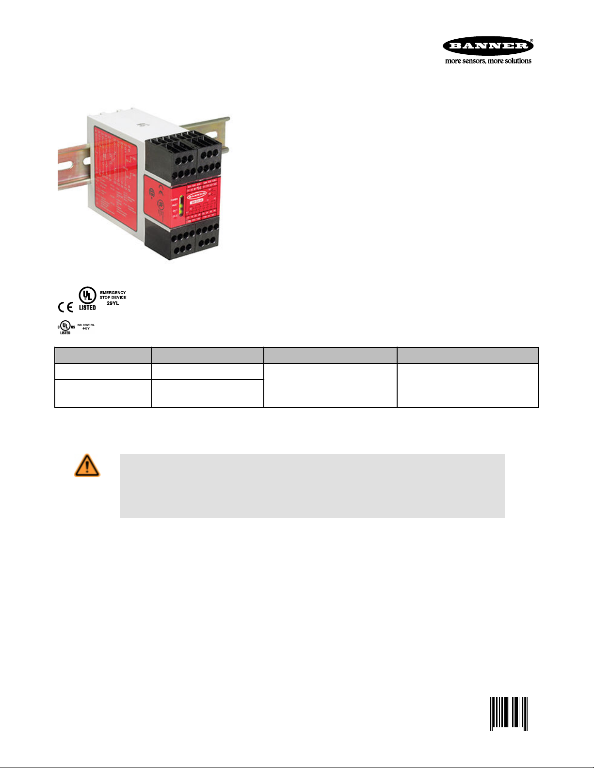
SM-xA-5A Safety Mat Monitoring Modules
0 122364 4
SM-GA-5A (12-24V dc / 115V ac operation) and SM-HA-5A (12-24V dc / 230V ac operation)
The user is responsible for satisfying all local, state, and national laws, rules,
codes, and regulations relating to the use of this product and its application. Banner
Engineering Corp. has made every effort to provide complete application, installation, operation, and maintenance instructions. Please direct any questions regarding the use or installation of this product to the factory applications department at
the telephone numbers or address shown found at http://www.bannerengineer-
ing.com.
The user is responsible for making sure that all machine operators, maintenance
personnel, electricians, and supervisors are thoroughly familiar with and understand
all instructions regarding the installation, maintenance, and use of this product, and
with the machinery it controls. The user and any personnel involved with the installation and use of this product must be thoroughly familiar with all applicable standards, some of which are listed within the specifications. Banner Engineering Corp.
makes no claim regarding a specific recommendation of any organization, the accuracy or effectiveness of any information provided, or the appropriateness of the provided information for a specific application.
Model Supply Voltage Outputs Output Rating
SM-GA-5A 12-24V dc or 115V ac 4 Normally Open Safety
SM-HA-5A 12-24V dc or 230V ac
For complete technical information about this product, including dimensions, accessories, and specifications, see www.BannerEngineering.com and search
122364_web.
WARNING: Not a Stand-Alone Safeguarding Device
This Banner product is not a stand-alone point-of-operation guarding device, as defined by OSHA regulations. It is necessa-
ry to install point-of-operation guarding devices, such as safety light screens and/or hard guards, to protect personnel from hazardous
machinery. Failure to install point-of-operation guards on hazardous machinery can result in a dangerous condition which
could lead to serious injury or death.
1 Normally Closed Aux.
2 Solid-State Aux.
N.O. Safety Outputs: 6 A
N. C. Aux. Outputs: 5 A
SS Aux Outputs: 100 mA
for
Overview
Safety Mat Monitor Modules SM-GA-5A and SM-HA-5A (the "Safety Module") are used to verify the proper operation of 4-wire presence-sensing switching mats (sensors).
P/N 122364 rev. C 8/22/2012
Page 2
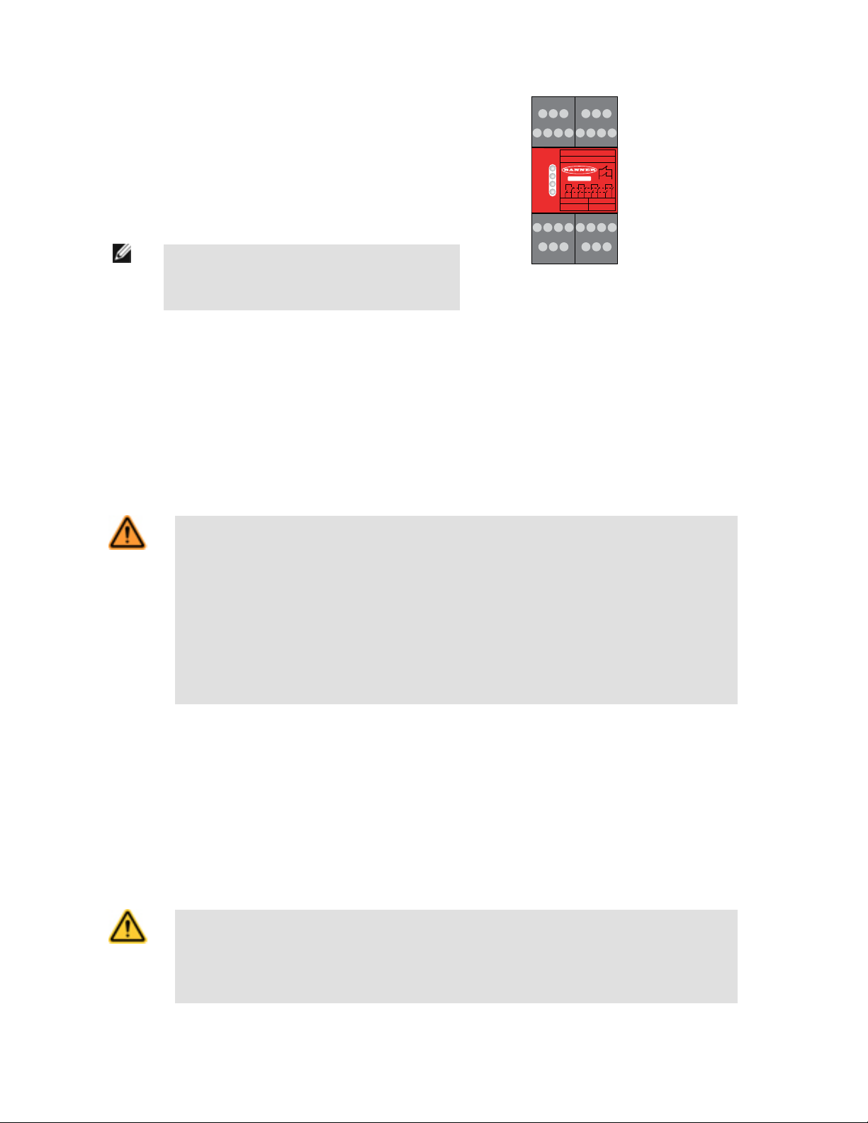
POWER
FAULT
CH. 1
CH. 2
K1
K2
51 52
13 14 23
A1 A2 B1 B2 S11 S12 S21 S22
24 33 34 43 44
Y30 Y31 Y32 Y35 51 52
S31 S32 S33 S34 S32 S35
SM-GA-5A
13
Y30 Y31 Y32
14 23 24 33
Y35 51 52
34 43 44
A1 A2 B1 B2 S11 S12 S21 S22
S31 S32 S33 S34 S32 S35
SM-xA-5A Safety Mat Monitoring Modules
Multiple mats may be switched in series to one Safety Module. The Safety Module provides the redundant safety outputs required for creating a control-reliable safety circuit. The Safety Module has two
functions:
•
To monitor the conductive elements (plates) and the wiring of one or more safety mat(s) for failures
and prevent the machine from restarting if any mat or the Module fails, and
• To provide a reset routine after the operator steps off the safety mat. This prevents the controlled
machinery from restarting automatically after the mat is cleared. This necessary reset/restart function is required by ANSI B11 and ANSI NFPA 79 machine safety standards. If the Module is used in
auto-reset mode, the reset/restart function must be provided by the machine control system.
NOTE:
NOTE:The Safety Module is not designed to monitor 2-wire mats,
bumpers, or edges (with or without sensing resistors).
Figure 1. Indicator and Terminal Locations
In operation, the Safety Module monitors the conductive elements (plates) of the pressure-sensitive mat for shorting of those elements (i.e., when the mat is stepped on)
and certain faults, such as shorts to other sources of power or ground (0V), or open connecting wires. With a +24V dc supply, Channel 1 (S11-S12) supplies > 20V dc that
is pulsed low and Channel 2 (S21-S22) supplies < 2V that is pulsed high; when these two channels are shorted together, the safety output contacts open (13-14, 23-24,
33-34, and 43-44).
If a fault is detected, the Module will lock out, open its safety outputs, and indicate the problem on its LED display, which can be diagnosed by using the troubleshooting
table in this document. After repairing the fault, step on the mat and off it again to clear the lockout condition (or cycle power). If the fault has been cleared and no other
faults exist, the Fault LED turns OFF and the Module can be reset (if configured for Auto Reset, the safety outputs will turn ON immediately).
The output relays energize automatically if the Module is wired for Auto Reset mode, all sensors are clear, all faults are removed or corrected, and power is applied. The
Module requires a manual reset if it is wired for Manual Reset mode.
WARNING: Application of Safety Mats
Requirements vary widely for the level of control reliability or category as described by ISO 13849-1 (EN 954-1) in the application of
safety mats. While Banner Engineering always recommends the highest level of safety in any application, it is the responsibility of
the user to safely install, operate, and maintain each safety system per the manufacturer's recommendations and comply
with all relevant laws and regulations.
Do not use safety mats as a tripping device to initiate machine motion (such as in a presence-sensing device initiation applica-
tion), due to the possibility of unexpected start or re-start of the machine cycle resulting from failure(s) within the mat and the interconnect cabling.
Do not use a safety mat to enable or provide the means to allow the machine control to start hazardous motion by simply
standing on the safety mat (e.g., at a control station). This type of application uses reverse/negative logic and certain failures (e.g.,
loss of power to the Module) can result in a "false" enable signal.
Mechanical Installation
Route the mat cable to the Safety Module location. The Safety Module must be installed inside an enclosure. It is not designed for exposed wiring. It is the user’s responsibility to house the Safety Module in an enclosure with NEMA 3 (IEC IP54) rating, or better.
The Safety Module mounts directly to standard 35 mm DIN rail; see Dimensions.
Heat Dissipation Considerations. For reliable operation, ensure that the operating specifications are not exceeded. The enclosure must provide adequate heat dissipation, so that the air closely surrounding the Module does not exceed the maximum operating temperature stated in the Specifications. Methods to reduce heat build-up
include venting, forced airflow (e.g., exhaust fans), adequate enclosure exterior surface area, and spacing between modules and other sources of heat.
Electrical Installation
CAUTION: Shock Hazard
Always disconnect power from the Banner product and the guarded machine before making any connections or replacing any component. Electrical installation and wiring must be made by qualified personnel and must comply with the NEC (National Electrical
Code), ANSI NFPA79 or IEC 60204-1 and -2, and all applicable local standards and codes. Use extreme caution to avoid electri-
cal shock at all times. Serious bodily injury or death could result.
2 www.bannerengineering.com - tel: 763-544-3164 P/N 122364 rev. C
Page 3

SM-xA-5A Safety Mat Monitoring Modules
The Safety Module is powered by either a 12-24V dc supply at 4W or an ac supply (115V ac, model SM-GA-5A, or 230V ac, model SM-HA-5A) at 7VA. The sensor circuit,
which monitors the conductive elements (plates) of the safety mat, consists of two channels (A and B) that issue a stop command (i.e., open the safety outputs) when an
individual steps onto the safety mat, shorting the two channels together.
It is not possible to give exact wiring instructions for a safety module which interfaces to a multitude of machine control configurations. The following guidelines are general
in nature.
Since the Safety Module functions by detecting the short circuit between the channels, resistance to electrical current flow in the contact monitoring circuit impacts the
operation and the safety of the system. Total resistance includes contact resistance of the internal mat contacts, the number of mats in the circuit, and the wire resistance of
the interconnect cables and connections.
The only limitation on the number of mats that can be connected in series is the amount of resistance. The total resistance within each channel can not exceed 250 ohms
when the Module is supplied by 24V dc or an ac power supply, and no more than 25 ohms when the Module is supplied by 12V dc.
The resistance between the channels when shorted together (i.e., when an individual steps on the mat) can not exceed 150 ohms (24V dc or an ac supply) or 10 ohms
(12V dc supply).
WARNING: Multiple Safety Mats
Whenever two or more safety mats are connected to the same Safety Mat Monitor Module, the corresponding conductive elements
(plates) of all mats must be connected together in series, as shown in the hookup drawing. Never connect the conductive ele-
ments (plates) of multiple safety mats in parallel; this defeats the ability of the Safety Module to detect open connection
wires to each mat, which would create an unsafe condition that could result in serious injury or death.
NOTE: The minimum amount of time for the Module to detect a STOP condition is 15 ms. This "recovery time" (OFF state) is required for the internal integrity tests to
complete, allowing a reliable reset to occur. A lockout may occur if the Module is cycled too quickly. To clear the lockout, the inputs must be re-cycled, meeting the minimum recovery time requirements.
Safety Mat Device Checkout - Prior to Module Connection
Before connecting the safety mat to the Module, verify the installation does not exceed the maximum resistance specification. Check the mat with an ohmmeter to verify
that none of the following values are exceeded.
1.
Check the leadwire resistance.
a) Keeping track of which wire goes to which terminal, disconnect all 4 wires from the terminal blocks.
b) Measure and record the resistance between the wires going to terminals S11 and S12: ________ (=Ra)
c) Measure and record the resistance between the wires going to terminals S21 and S22: ________ (=Rb)
d) Review the values for Ra and Rb.
If both Ra and Rb are Then
Less than 50 ohms The lead resistance is acceptable for all supply voltages; check the mat resistance next. If it is 50 ohms or more for either, continue below.
Less than 500 ohms The lead resistance is acceptable for an AC supply and for a DC supply >20 V. If resistance is acceptable for your supply, check the mat
resistance next. If resistance is not acceptable, lower the lead resistance by shortening the leadwires or by increasing the wire diameter.
Recheck Ra and Rb.
2. Check the mat resistance.
Step on the mat in various locations while taking the measurements listed below.
a)
b) Measure and record the highest observed resistance between S11 and S21: ________ (=Rc)
c) Measure and record the highest observed resistance between S21 and S22: ________ (=Rd)
d) Review the values for Rc and Rd.
If both Rc and Rd are Then
Less than 10 ohms The mat and leadwire resistance is acceptable for all supply voltages and the safety mat checkout is
complete.
Less than 150 ohms AND you are using an AC supply
The mat and leadwire resistance is acceptable and the safety mat checkout is complete.
or DC supply greater than 20V dc
Any other value If resistance is not acceptable, proceed to the next step.
3. Connect the ohmmeter to the wires to be connected to S11-S12 (Channel A), and note the resistance.
Connect the ohmmeter to the wires to be connected to S21-S22 (Channel B), and note the resistance.
4.
5. Perform the following calculation: Rm = (Rc + Rd - Ra - Rb)/2.
If Rm is: Then
Less than 10 ohms The mat resistance is acceptable for all supply voltages; the safety mat checkout is complete.
P/N 122364 rev. C www.bannerengineering.com - tel: 763-544-3164 3
Page 4

SM-xA-5A Safety Mat Monitoring Modules
If Rm is: Then
Less than 150 ohms AND you are using an AC
supply or DC supply greater than 20V dc
Any other value The resistance in the mat is too high for safe operation. Replace the safety mat. Repeat the mat resistance
WARNING: Safety Mat Resistance Values
Exceeding the maximum resistance between the monitoring channels (usually due to degradation of the mat) can result in
the increase of response time or complete loss of the sensing function of the safety mat, when it is stepped on (shorted).
This can result in serious injury or death.
Exceeding the maximum resistance within a contact monitoring channel can result in the Module issuing a stop command (opening
the safety outputs) when no person is present.
To ensure proper operation, verify the quality and specifications of the mat being connected to this Module, and perform
periodic checks of the safety mat's resistance, as described in the Safety Mat Initial Checkout.
The mat resistance is acceptable and the safety mat checkout is complete.
checkout for the new mat.
Reset Switch Connection
The reset circuit switch can be any mechanical switch, such as a normally open momentary switch, or a two-position key switch. The reset switch must be capable of
reliably switching 12 to 30V dc at 20 to 50 milliamps. As shown in the hookup drawings, the reset switch connects between Safety Module terminals S33 and S34.
The reset switch must be located outside of – and not be accessible from – the area of dangerous motion, and must be positioned so that any area of dangerous motion
may be observed by the switch operator during the reset procedure. See warning below.
WARNING: Reset Switch Location
All reset switches must be accessible only from outside, and in full view of, the hazardous area. Reset switches must also
be out of reach from within the safeguarded space, and must be protected against unauthorized or inadvertent operation
(e.g., through the use of rings or guards). If any areas are not visible from the reset switch(es), additional means of safeguarding
must be provided. Failure to do so could result in serious bodily injury or death.
WARNING: Reset Routine Required
U.S. and international standards require that a reset routine be performed after clearing the cause of a stop condition (e.g., arming an
E-stop button, closing an interlocked guard, etc.). Allowing the machine to restart without actuating the normal start command/
device can create an unsafe condition which could result in serious injury or death.
Automatic Reset Mode
The Safety Module may be configured (via hookup) for automatic reset. If no MSC contacts are monitored, install a jumper between terminals S32 and S35 (see hookups).
The Safety Module will reset (and its outputs energize) as soon as the switch returns to its armed (closed-contact) position.
Automatic reset is useful for some automated processes. However, if automatic reset is used, it is necessary to provide a means of preventing resumption of
hazardous machine motion, until an alternate reset procedure is performed. The alternate procedure must include a reset/restart switch, located outside the area of
dangerous motion and positioned so that any area of dangerous motion may be observed by the switch operator during the reset procedure. See Warning.
Connection to the Machine to be Controlled
The machine hookup diagram shows a generic connection of the Safety Module's redundant output circuits to the master stop control elements (MSCs). An MSC is defined
as an electrically powered device, external to the Safety Module, which stops the machinery being controlled by immediately removing electrical power to the machine and
(when necessary) by applying braking to dangerous motion. This stopping action is accomplished by removing power to the actuator of either MSC.
Overvoltage Category II and III Installations (EN 50178 and IEC 60664-1)
The Safety Module is rated for Overvoltage Category III when voltages of 1V to 150V ac/dc are applied to the output relay contacts. It is rated for Overvoltage Category II
when voltages of 151V to 250V ac/dc are applied to the output relay contacts and no additional precautions are taken to attenuate possible overvoltage situations in the
supply voltage. The Module can be used in an Overvoltage Category III environment (with voltages of 151V to 250V ac/dc) if care is taken either to reduce the level of
electrical disturbances seen by the Module to Overvoltage Category II levels by installing surge suppressor devices (e.g., arc suppressors), or to install extra external
insulation in order to isolate both the Safety Module and the user from the higher voltage levels of a Category III environment.
4 www.bannerengineering.com - tel: 763-544-3164 P/N 122364 rev. C
Page 5
SM-xA-5A Safety Mat Monitoring Modules
For Overvoltage Category III installations with applied voltages from 151V to 250V ac/dc applied to the output contact(s): the Safety Module may be used under
the conditions of a higher overvoltage category where appropriate overvoltage reduction is provided. Appropriate methods include:
•
An overvoltage protective device
• A transformer with isolated windings
• A distribution system with multiple branch circuits (capable of diverting energy of surges)
• A capacitance capable of absorbing energy of surges
• A resistance or similar damping device capable of dissipating the energy of surges
When switching inductive ac loads, it is good practice to protect the Safety Module outputs by installing appropriately-sized arc suppressors. However, if arc suppressors
are used, they must be installed across the load being switched (e. g., across the coils of external safety relays), and never across the Safety Module’s output contacts (see
WARNING, Arc Suppressors).
External Device Monitoring
To satisfy the requirements of Control Reliability (OSHA and ANSI), Category 3 and 4 of ISO 13849-1 (EN 954-1), the Master Stop Control Elements (MSCs) must each
offer a normally closed, forced-guided (mechanically linked) monitor contact. Connect one normally closed monitor contact from each master stop control element in series
to S31 and S32.
In operation, if one of the switching contacts of either MSC fails in the energized condition, the associated monitor contact will remain open. Therefore, it will not be possible
to reset the Safety Module. If no MSC-monitor contacts are monitored, a jumper must be installed between terminals S31-S32, as shown in the hookup drawings. It is the
user's responsibility to ensure that any single failure will not result in a hazardous condition and will prevent a successive machine cycle.
Auxiliary Monitor Contact/Solid-State Monitor Outputs Connection
The action of the auxiliary monitor contact, terminals 51-52, inversely "follows" the action of the safety outputs. Two additional solid-state monitor outputs (at terminals Y32
and Y35) each are capable of switching up to 100 mA at 12- 24V dc. The output at terminal Y32 follows the action of the output circuits (K1 and K2); the output at terminal
Y35 opens (low signal) when there is a loss of power or a fault is detected. These outputs are to be used only for nonsafety functions (typically, to communicate the status
of the Safety Module to a programmable logic controller). See the appropriate figure for hookup information.
WARNING: Wiring of Arc Suppressors
If arc suppressors are used, they MUST be installed as shown across the actuator coil of the stop control elements (MSCs or
MPCEs). NEVER install suppressors directly across the output contacts of the Safety Device or Module. It is possible for
suppressors to fail as a short circuit. If installed directly across the output contacts, a short-circuited suppressor will create an
unsafe condition which could result in serious injury or death.
WARNING: Interfacing MSCs
NEVER wire an intermediate device(s) (e.g., PLC, PES, PC) between the Safety Module outputs and the Master Stop Control Element it switches in such a manner that in the event of a failure there is a loss of the safety stop command, OR in such a manner that
the safety function can be suspended, overridden, or defeated, unless accomplished with the same or greater degree of safety.
Whenever forced-guided, mechanically linked relays are added as intermediate switching devices, a normally closed forced-guided
monitor contact from each relay must be added to the series feedback loop between Safety Module terminals S31 and S32.
Safety Mat Module Initial Checkout Procedure
WARNING:
Checkouts for Multiple Safety Devices. If more than one safety mat is series-connected to one Safety Mat Monitor Module, run this
checkout procedure individually for each mat.
CAUTION: Disconnect Power Prior to Checkout
Before performing the initial checkout procedure, make certain all power is disconnected from the machine to be control-
led.
Dangerous voltages may be present along the Safety Module wiring barriers whenever power to the machine control elements is ON.
Exercise extreme caution whenever machine control power is or may be present. Always disconnect power to the machine
control elements before opening the enclosure housing of the Safety Module.
P/N 122364 rev. C www.bannerengineering.com - tel: 763-544-3164 5
Page 6

SM-xA-5A Safety Mat Monitoring Modules
1. Remove power to the machine control elements, if it is already connected.
2.
Apply force to the mat’s sensing area, using a test piece as outlined in the mat manufacturer’s literature, or the appropriate standard.
3. Apply input power to the Safety Mat Monitor Module at terminals A1 and A2 or B1 and B2. Verify that only the Power indicator LED is ON.
4. Remove the test piece from the safety mat (clear the mat sensing area).
5. Manual Reset mode: Ch1 and Ch2 indicators should be flashing. Close and reopen the Reset switch.
6. Verify that the Ch1 and Ch2 indicators both come ON. If only one indicator comes ON or if any indicator is flashing, refer to the Troubleshooting section for more
information. Return to step 2 after correcting the problem.
7. Apply force in several locations (using a test piece) to the mat’s sensing area, per the mat manufacturer’s recommendations. Verify that the Ch1 and Ch2 indicators
turn OFF simultaneously. If either indicator does not go OFF, disconnect the input power and check all wiring. Return to step 2 after correcting the problem.
8. Repeat for each safety mat individually.
9. Close and secure the enclosure. Apply power to the machine control elements and perform the following Periodic Checkout Procedure.
Specifications
Category Specification
Supply Voltage and Current
Power Consumption Approx. 4W/7VA
Supply Protection Circuitry Protected against transient voltages and reverse polarity
Overvoltage Category Output relay contact voltage of 1V to 150V ac/dc: category III
Pollution Degree 2
Relay Outputs 4 normally open (N.O.) output channels and 1 normally closed (N.C.) output
AI-A2: 115V ac (model SM-GA-5A) or 230V ac (model SM-HA-5A) ±15%, 50/60Hz
BI-B2: 11V dc – 27.6V dc
Connect the Safety Module only to a SELV (safety extra-low voltage, for circuits without earth ground) or a PELV (protected extra-low
voltage, for circuits with earth ground) power supply, according to EN IEC 60950, NEC Class 2.
Output relay contact voltage of 151V to 250V ac/dc: category III, if appropriate overvoltage reduction is provided, as described earlier.
Each normally open output channel is a series connection of contacts from two forced-guided (mechanically linked) relays, K1-K2. The
normally closed Aux. output channel is a parallel connection of contacts from two forced-guided relays, K1-K2.
Contacts: AgNi, 5 μm gold-plated
Low Current Rating: The 5 μm gold-plated contacts allow the switching of low current/low voltage. In these low-power applications, multiple contacts can also be switched in series (e.g., “dry switching”). To preserve the gold plating on the contacts, do not exceed the following max. values at any time:
Min. voltage: 1V ac/dc
Min. current: 5 mA ac/dc
Min. power: 5 mW (5 mVA)
High Current Rating: If higher loads must be switched through one or more of the contacts, the minimum and maximum values of the
contact(s) changes to:
Minimum Maximum
Voltage: 15V ac/dc N.O. Safety Contacts (13-14, 23-24, 33-34, 43-44): 250V
Current: 250 mA ac/dc N.C. Auxiliary Contact (51-52): 250V ac / 24V dc, 5A resis-
Power: 5 W (5 VA)
Minimum Maximum — IEC60947-5-1
Voltage: 15V ac/dc N.O. Safety Contacts:
Current: 250 mA ac/dc N.C. Auxiliary Contact:
Max. voltage: 60V
Max. current: 300 mA
Max. power: 7 W (7 VA)
ac / 24V dc, 6A resistive
B300, Q300 (UL508)
tive
B300, Q300 (UL508)
AC-1: 250V ac, 6A; DC-1: 24V dc, 6A
AC-15: 230V ac, 3A; DC-13: 24V dc, 4A
6 www.bannerengineering.com - tel: 763-544-3164 P/N 122364 rev. C
Page 7
SM-xA-5A Safety Mat Monitoring Modules
Category Specification
AC-1: 250V ac, 5A; DC-1: 24V dc, 5A
AC-15: 230V ac, 2A; DC-13: 24V dc, 4A
Power: 5 W (5 VA)
Mechanical life: > 50,000,000 operations
Electrical life: 150,000 cycles @ 1500 VA; 1,000,000 cycles @ 450 VA; 2,000,000 cycles @ 250 VA; 5,000,000 cycles @ 125 VA
NOTE: Transient suppression is recommended when switching inductive loads. Install suppressors across load. Never install suppressors across output contacts (see Warning, Wiring of Arc Suppressors).
Solid-State Outputs Two non-safety solid-state dc outputs
Output circuits require application of +12-24V dc ± 15% at terminal Y31; dc common at Y30.
Max. switching current: 100 mA at 12-24V dc
Both outputs are protected against short circuits.
Output at Y32 monitors state of outputs – conducts (output high) when both K1 and K2 are energized.
Output at Y35 conducts (output high) when in normal operation (no lockout).
Output Response Time 35 ms max. (25 ms typical)
Input Requirements Safety mat normally open contact must be capable of switching 20 to 100 mA @ 12 to 30V dc; and must be closed > 25 ms for a valid
OFF-State Recovery Time 350 ms maximum
Indicators 3 green LED indicators: Power ON, Channel 1 (high side), Channel 2 (low side)
Construction Polycarbonate housing. Rated NEMA 1, IEC IP20
Mounting Mounts to standard 35 mm DIN rail track. Safety Module must be installed inside an enclosure rated NEMA 3 (IEC IP54), or better.
Vibration Resistance 10 to 60 Hz @ 0.35 mm peak displacement per UL 991
Operating Conditions Temperature: 0° to +50°C (+32° to 122°F), (surrounding air)
Design Standards Cat. 4 PL e per EN ISO 13849-1; SIL 3 per IEC 61508 and IEC 62061
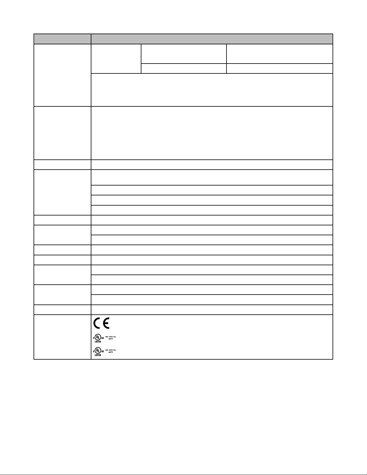
Certifications
stop command.
V ac or 24V dc Supply: Max. lead resistance 250 ohms; max. contact resistance: 150 ohms.
12V dc Supply: Max. lead resistance 25 ohms; max. contact resistance: 10 ohms.
Reset switch: must have one normally open contact capable of switching 20 to 50 mA @ 12 to 30V dc.
1 red LED indicator: indicates a fault condition (see Troubleshooting)
60 to 150 Hz @ 5 g max.
Max. Relative Humidity: 90% @ +50°C (non-condensing)
EC Declaration of Conformity
Banner Engineering Corp. herewith declares that SM-GA-5A and SM-HA-5A Safety Mat Monitor Modules for industrial control are in conformity with the provisions of the
Machinery Directive (Directive 2006/42/EC), and all essential Health and Safety Requirements have been met. Download the complete EC Declaration of Conformity as a
PDF file at http://www.bannerengineering.com/SMmodule
Banner Engineering Corp Limited Warranty
Banner Engineering Corp. warrants its products to be free from defects in material and workmanship for one year following the date of shipment. Banner Engineering Corp.
will repair or replace, free of charge, any product of its manufacture which, at the time it is returned to the factory, is found to have been defective during the warranty
period. This warranty does not cover damage or liability for misuse, abuse, or the improper application or installation of the Banner product.
THIS LIMITED WARRANTY IS EXCLUSIVE AND IN LIEU OF ALL OTHER WARRANTIES WHETHER EXPRESS OR IMPLIED (INCLUDING, WITHOUT LIMITATION,
ANY WARRANTY OF MERCHANTABILITY OR FITNESS FOR A PARTICULAR PURPOSE), AND WHETHER ARISING UNDER COURSE OF PERFORMANCE,
COURSE OF DEALING OR TRADE USAGE.
P/N 122364 rev. C www.bannerengineering.com - tel: 763-544-3164 7
Page 8

SM-xA-5A Safety Mat Monitoring Modules
This Warranty is exclusive and limited to repair or, at the discretion of Banner Engineering Corp., replacement. IN NO EVENT SHALL BANNER ENGINEERING CORP. BE
LIABLE TO BUYER OR ANY OTHER PERSON OR ENTITY FOR ANY EXTRA COSTS, EXPENSES, LOSSES, LOSS OF PROFITS, OR ANY INCIDENTAL, CONSEQUENTIAL OR SPECIAL DAMAGES RESULTING FROM ANY PRODUCT DEFECT OR FROM THE USE OR INABILITY TO USE THE PRODUCT, WHETHER ARISING IN CONTRACT OR WARRANTY, STATUTE, TORT, STRICT LIABILITY, NEGLIGENCE, OR OTHERWISE.
Banner Engineering Corp. reserves the right to change, modify or improve the design of the product without assuming any obligations or liabilities relating to any product
previously manufactured by Banner Engineering Corp.
 Loading...