

Page 1
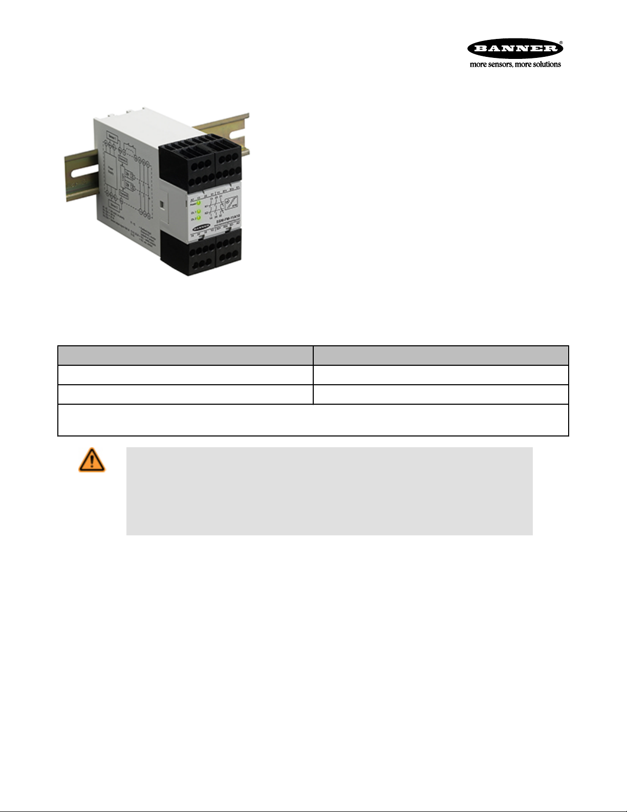
SSM-FM-11A... Safe Speed Monitoring Modules
For over-speed, under-speed, and zero-speed detection
• Dual-channel redundancy
• Monitors 2 sensors with PNP outputs
• Monitors rotation (rpm) or linear movement
• LED indication for power, input 1 and input 2
• 24V ac/dc operation
• Feedback input monitors external machine control elements
• Two normally open (N.O.) and one normally closed (N.C.) output switching
channels for connection to control-reliable power interrupt circuits rated at
4A
• Stop Category 0, per ISO 13850 (EN 418)
• SIL Claimed Level (SIL CL) 3 to EN 62061
• Performance Level (PL) e / Category 3 to DIN EN ISO 13849-1
• DIN-rail mountable 45 mm wide housing with removable terminal blocks
• Energizes output relays (closes N.O. contacts), when speed drops below
set value, for "standstill" (under-speed) monitoring
• De-energizes output relays (opens N.O. contacts), when speed rises above
set value, for over-speed monitoring
Models Detectable Speed Range *
SSM-FM-11A10 5 to 10,500 ipm
SSM-FM-11A20 10 to 20,000 ipm
* The unit "ipm" (impulses per minute) may be equal to actual machine rpm, or may be a multiple, depending on the number of sensing
points used.
WARNING: Not a Stand-Alone Safeguarding Device
This Banner product is not a stand-alone point-of-operation guarding device, as defined by OSHA
regulations. It is necessary to install point-of-operation guarding devices, such as safety light screens
and/or hard guards, to protect personnel from hazardous machinery. Failure to install point-of-operation
guards on hazardous machinery can result in a dangerous condition which could lead to serious
injury or death.
P/N 140782_web
rev. C
8/22/2012
Page 2

SSM-FM-11A... Safe Speed Monitoring Modules
Important... read this before proceeding!
The user is responsible for satisfying all local, state, and national laws, rules, codes, and regulations relating to the use of this
product and its application. Banner Engineering Corp. has made every effort to provide complete application, installation, operation, and
maintenance instructions. Please direct any questions regarding the use or installation of this product to the factory applications department at the telephone numbers or address shown found at http://www.bannerengineering.com.
The user is responsible for making sure that all machine operators, maintenance personnel, electricians, and supervisors are thoroughly familiar with and understand all instructions regarding the installation, maintenance, and use of this product, and with the machinery it
controls. The user and any personnel involved with the installation and use of this product must be thoroughly familiar with all applicable
standards, some of which are listed within the specifications. Banner Engineering Corp. makes no claim regarding a specific recommendation of any organization, the accuracy or effectiveness of any information provided, or the appropriateness of the provided information
for a specific application.
Applicable U.S. Standards
ANSI B11.0 Safety of Machinery, General Requirements, and Risk Assessment
Contact: Safety Director, AMT – The Association for Manufacturing Technology, 7901 Westpark Drive, McLean, VA 22102, Tel.:
703-893-2900
ANSI NFPA 79 Electrical Standard for Industrial Machinery
Contact: National Fire Protection Association, 1 Batterymarch Park, P.O. Box 9101, Quincy, MA 02269-9101, Tel.: 800-344-3555
ANSI/RIA R15.06 Safety Requirements for Industrial Robots and Robot Systems
Contact: Robotic Industries Association, 900 Victors Way, P.O. Box 3724, Ann Arbor, MI 48106, Tel.: 734-994-6088
Applicable International Standards
ISO 12100-1 & -2 (EN 292-1 & -2) Safety of Machinery – Basic Concepts, General Principles for Design
IEC 62061 Functional Safety of Safety-Related Electrical, Electronic and Programmable Control Systems
ISO 13849-1 (EN 954-1) Safety-Related Parts of Control Systems
Contact: Global Engineering Documents, 15 Inverness Way East, Englewood, CO 80112-5704, Tel.: 800-854-7179
Certificate of Adequacy
This document (p/n 140782) satisfies the requirements of Machinery Directive 2006/42/EC, Section 1.7.4 — instructions.
EC Declaration of Conformity
Date: 10/07/2009
We herewith declare that SSM-FM-11A10 and SSM-FM-11A20 Safe Speed Monitoring Modules for industrial control are in conformity
with the provisions of the Machinery Directive (Directive 98/37/EEC), and all essential Health and Safety Requirements have been met.
R. Eagle / Engineering Manager
Banner Engineering Corp. · 9714 Tenth Avenue North · Minneapolis, MN 55441-5019 USA
Download the complete EC Declaration of Conformity as a PDF file at www.bannerengineering.com/SSMmodule
2 www.bannerengineering.com - tel: 763-544-3164 P/N 140782_web
rev. C
Page 3
1
3
2
SSM-FM-11A... Safe Speed Monitoring Modules
Overview
The SSM-FM-11A.. Safe Speed Monitoring Module ("the Module") can be used to monitor a rotating or laterally moving device's stopping,
starting, or speed. The Module requires signals from two independent sensors.
As a "standstill" (under-speed) monitor, the Module is often used in combination with hard guarding, access doors, and safety gates with
solenoid-lock or -unlock safety switches. When the speed of the monitored device drops below the set switch point (where its speed is no
longer considered dangerous), the Module closes its safety output contacts, applying power to the safety switch solenoid, releasing the
switch lock and enabling the operator to open the safety gate.
In over-speed monitor applications, the N.O. safety contacts are closed for operation (when the motor speed of the monitored device is
below the set switch point). When the speed exceeds the set value, indicating a too-high (dangerous) speed, the safety output contacts
open.
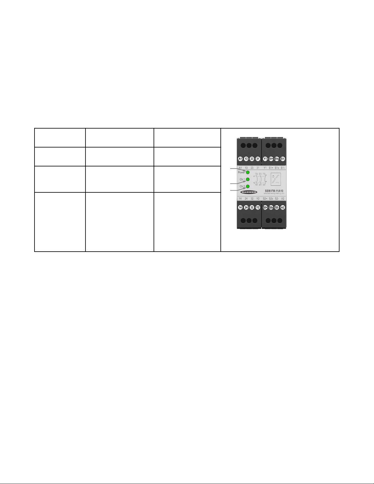
Indicators
1. Power ON (green)
Standstill / Under-speed
Monitoring Applications
Power is applied Power is applied
Over-speed Monitoring Applications
when
2. Safety output
channel 1 ON
Standstill signal detected on
Input Channel 1
No over-speed detected on
Input Channel 1
(green) when
2. Safety output
channel 2 ON
Standstill signal detected on
Input Channel 2
No over-speed detected on
Input Channel 2
(green ) when
Figure 1. SSM-FM-11A... features and terminal
locations
Operation and Requirements
The Module is redundant and self-checking. It requires digital input signals from two independent input sensors (e.g., proximity switches)
to monitor for either standstill (under-speed) or over-speed conditions.
The input channels are factory pre-adjusted for simultaneity, and a simultaneity potentiometer (behind the Module front cover) is available
to further synchronize the input channel timing. Two banks of DIP switches are also located behind the front cover, for the purpose of
selecting the switch point range; a second potentiometer is used to fine-tune the switch point setting. See Figure, "Module adjustments."
P/N 140782_web
rev. C
www.bannerengineering.com - tel: 763-544-3164 3
Page 4

t
t
ds
Res
+
Res
t
ds
t
do
13-14
23-24
Stop
Stop
Stop
Motor Standstill
Motor ON
Supply ON
Standstill Detection
Overspeed Detection
Motor ON
Overspeed
S1s
0V
A1/A2 +24V
S1s: Output signal from sensor A
Motor
Speed
S2s
Motor Standstill
Motor Standstill
Motor ON
Motor ON
Motor OFF
Motor ON
S2s: Output signal from sensor B
t : Power-up delay
detection
t : Response after overspeed detection
do
ds
t : Response after standstill/underspeed
SSM-FM-11A... Safe Speed Monitoring Modules
Input Sensor Requirements
Both sensors must have 24V PNP outputs. Because the Module continually monitors its connections to each sensor, each sensor must
draw a minimum current of 3 mA at all times (in either the OFF or ON
state). The Module will detect if any of the three wires from the sensor to the Module are interrupted. A broken sensor wire will always
result in an OFF condition.
• If the safety outputs are ON when a sensor wire breaks or is disconnected, the related internal relay turns OFF and the safety
outputs open, signaling "No Standstill" and/or "Over-speed."
• If the safety outputs are OFF when a sensor wire breaks or is disconnected, they can not turn ON (again signaling "No Standstill"
and/or "Over-speed") until the sensor connection is fixed.
Sensor Mounting Requirements: For safe and reliable operation,
the two input sensors must be mounted so that they are vibrationfree, their signals are received simultaneously, and they don't influence each other.
Figure 2. Functional Diagram
Mechanical Installation
The Safety Module must be installed inside an enclosure.
It is not designed for exposed wiring. It is the user’s responsibility to house the Safety Module in an enclosure with NEMA 3 (IEC IP54)
rating, or better. The Safety Module mounts directly to standard 35 mm DIN rail; see Dimensions.
Heat Dissipation Considerations
For reliable operation, ensure that the operating specifications are not exceeded. The enclosure must provide adequate heat dissipation,
so that the air closely surrounding the Module does not exceed the maximum operating temperature stated in the Specifications. Methods
to reduce heat build-up include venting, forced airflow (e.g., exhaust fans), adequate enclosure exterior surface area, and spacing between modules and other sources of heat.
Electrical Installation
It is not possible to give exact wiring instructions for a Safety Module which interfaces to a multitude of machine control configurations.
The following guidelines are general in nature.
The Safety Module has no delay function. Its output relay contacts open within the time frame determined by the formula shown in the
Configuration section. This classifies the Safety Module as functional stop "Category 0", as defined by ANSI NFPA 79 and IEC/EN
60204-1.
Input Sensor Connections
The Module provides 24V dc and 0V to power the sensors through S1+/S1- and S2+/S2-. The sensor output signals are connected to
terminals S1s and S2s.
4 www.bannerengineering.com - tel: 763-544-3164 P/N 140782_web
rev. C
Page 5
SSM-FM-11A10
or
SSM-FM-11A20
Sensor 2
24V ac/dc
0 V
K1
A
4 A max.
K2
A
K1
B
K2
B
K1
C
K2
C
Y1
MSC1
MSC
Monitor
Contacts
or Jumper
MSC2
+24V
0V
PNP
Signal
Out
13
S2+
S2s
S2-
Sensor 1
+24V
0V
PNP
Signal
Out
S1+
A2A1
S1s
S1-
14
24
31 32
Y2
23
See External Device
Monitoring
0V
0V
n.c.
K1
A
K2
A
K1
B
K2
B
K1
C
K2
C
13
14
23
24
33
34
ES-FA-9AA
SSM-FM-11A10
or
SSM-FM-11A20
Sensor 2
24V ac/dc
0V
K1
A
4A max.
K2
A
K1
B
K2
B
K1
C
K2
C
Machine
Control
Circuits
Y1
Unlock (3)
OK to Open
+24V
0V
PNP
Signal
Out
13
S2+
S2s
S2-
Sensor 1
+24V
0V
PNP
Signal
Out
S1+
A2A1
S1s
S1-
14
24
31 32
Y2
23
S12
S22
S21
24V ac/dc
Start
Function
(7)
A2
S34
OPEN
E1
E2
0V
0V
(5)
MPCE
1
MPCE
2
A1
S33
24V
ac/dc
(6)
MPCE1 MPCE2
Request to
Enter (2)
S11
Reset
(1)
M
MPCE1 MPCE2
(5)
(4)
SSM-FM-11A... Safe Speed Monitoring Modules
Reset and Startup Conditions
The Module works only in automatic reset mode. In order for the Module to
switch to RUN mode for normal operation, the Y1 - Y2 feedback input
must be closed during power-up.
The Module typically requires two to three seconds after power ON to
evaluate the signals from the two sensors and to decide if the number of
incoming signals/pulses is above or below the set switch point value. After
three seconds, if the Module detects a number of pulses per minute below
the set value, the relays energize and the output contacts turn ON, indicating a standstill condition. If the machine being monitored and the Module
are powered up at the same time, the machine has only three seconds to
come up to speed, or the Module detects a standstill condition. If the machine requires more than three seconds, power up the machine first, then
the Module, after the appropriate delay.
When each of the internal relays is energized, its corresponding LED turns
ON green. Both relay outputs activate only if both inputs reach the enabling conditions within approximately two seconds. If the signals are not
received within two seconds (e.g., because of a defective sensor or because the channels did not switch simultaneously), the output contacts will
not turn ON, and power to the Module must be cycled.
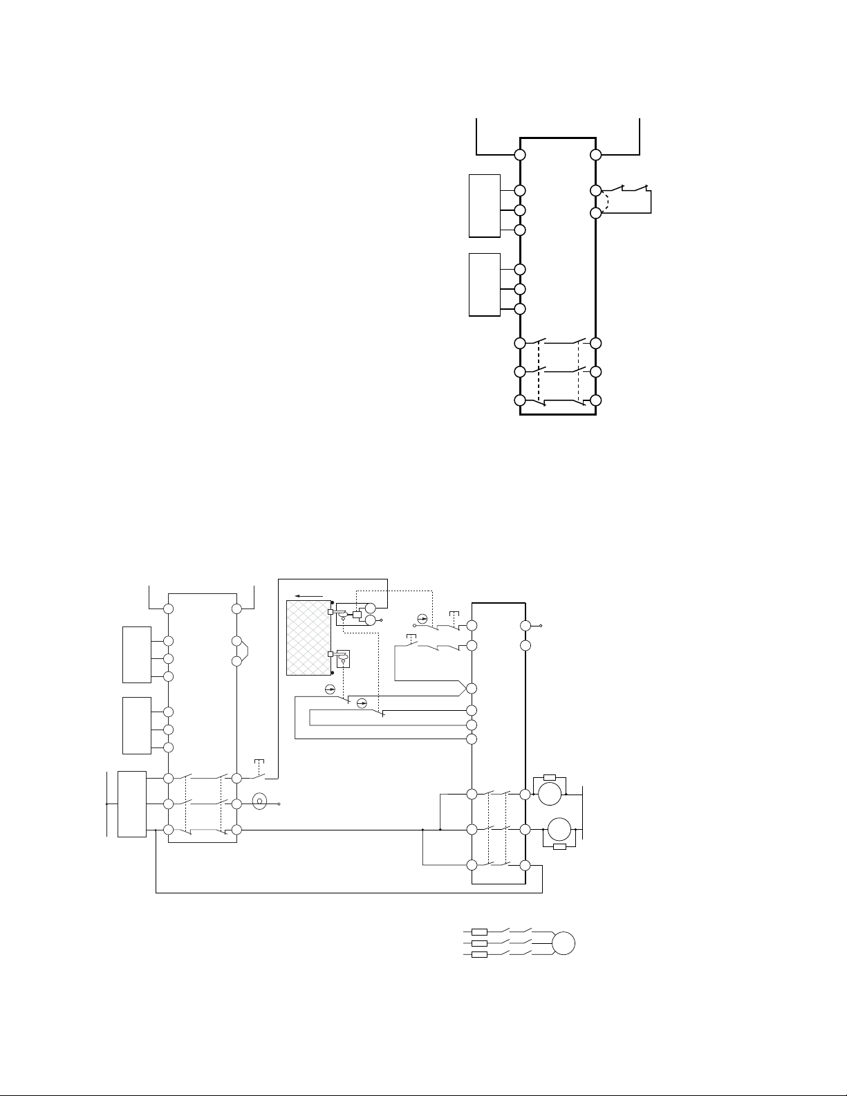
Figure 3. Typical hookup to two sensors
Connection to the Machine to be Controlled
The machine hookup diagram shows a generic connection of the Safety Module's redundant output circuits to the Machine Primary Control Elements MPCE1 and MPCE2. A Machine Primary Control Element is an electrically powered device, external to the Interface Module, which stops the machinery being controlled by immediately removing electrical power from the machine and (when necessary) by
applying braking to dangerous motion.
NOTES:
P/N 140782_web
rev. C
Figure 4. Machine connection with an interlocked guard with guard locking and another safety module
www.bannerengineering.com - tel: 763-544-3164 5
Page 6

SSM-FM-11A... Safe Speed Monitoring Modules
1. Safety Module ES-FA-9AA is configured for manual reset. See data sheet p/n 60606 for complete information. Other Safety Modules can be used. Call Banner Engineering with all questions.
2. After the guard has been closed, the Safety Module has been reset, and the machine control has started the motor, the Request to
Enter button can be pushed to interrupt the cycle.
3. The machine control and the SSM Safe-Speed Monitoring Module enable the Unlock button and illuminate the OK to Open light.
4. The signal from the Unlock button energizes the solenoid locking mechanism of the locking style safety switch, allowing the guard
to be opened. It is recommended to locate the Unlock button near the associated guard. The solenoid contact prevents the reset of
the ES-FA-9AA Safety Module until the guard is locked.
5. Arc Suppressor, see Warning.
6. See the External Device Monitoring section and the warning, Interfacing MPCEs.
7. Not all feedback or monitoring functions of the machine interface are shown.
WARNING: WARNING . . . Interfacing MPCEs. NEVER wire any intermediate device(s) (e.g., PLC,
PES, PC), between the Safety Module outputs and the Machine Primary Control Elements (MPCE1
to MPCE3) it switches, in such a manner that in the event of a failure there is the loss of the safety
stop command, OR in such a manner that the safety function can be suspended, overridden, or
defeated, unless accomplished with the same or greater degree of safety. Whenever forced-guided,
mechanically linked relays are added as intermediate switching devices, a normally closed forced-guided
monitor contact from each relay must be added to the series feedback loop between Interface Module
terminals Y1 and Y2.
WARNING: WARNING . . . Wiring of Arc Suppressors. If arc suppressors are used, they MUST be
installed as shown across the coils of the Machine Primary Control Elements (MPCE1 to MPCE2). NEV-
ER install suppressors directly across the output contacts of the Safety Module. It is possible for suppressors to fail as a short circuit. If installed directly across the output contacts of the Interface Module, a shortcircuited suppressor will create an unsafe condition which could result in serious injury or death.
CAUTION: CAUTION . . . Shock Hazard. Always disconnect power from the Safety Module and all
power from the machine being controlled before making any wire connections. Electrical installation
and wiring must be made by qualified personnel and must comply with the NEC (National Electrical Code),
EN60204-1 and -2, and all applicable local standards and codes.
External Device Monitoring
To satisfy the requirements of Control Reliability (OSHA and ANSI), Category 3 and 4 of ISO 13849-1 (EN 954-1), the Machine Primary
Control Elements (MPCEs) must each offer a normally closed, forced-guided (mechanically linked) monitor contact. Connect one normally closed monitor contact from each Machine Primary Control Element as shown in the appropriate hookup drawing.
In operation, if one of the switching contacts of either MPCE fails in the energized condition, the associated monitor contact will remain
open. Therefore, it will not be possible to reset the Primary Safety Device . If no MPCE-monitor contacts are monitored, it is the user's
responsibility to ensure that any single failure will not result in a hazardous condition and will prevent a successive machine cycle.
Overvoltage Category II and III Installations (EN 50178 and IEC 60664-1)
The Safety Module is rated for Overvoltage Category III when voltages of 1V to 150V ac/dc are applied to the output relay contacts. It is
rated for Overvoltage Category II when voltages of 151V to 250V ac/dc are applied to the output relay contacts and no additional precautions are taken to attenuate possible overvoltage situations in the supply voltage. The Module can be used in an Overvoltage Category III
environment (with voltages of 151V to 250V ac/dc) if care is taken either to reduce the level of electrical disturbances seen by the Module
to Overvoltage Category II levels by installing surge suppressor devices (e.g., arc suppressors), or to install extra external insulation in
order to isolate both the Safety Module and the user from the higher voltage levels of a Category III environment.
For Overvoltage Category III installations with output contact voltage 151V to 250V ac/dc applied to the output contact(s): the
Safety Module may be used under the conditions of a higher overvoltage category where appropriate overvoltage reduction is provided.
Appropriate methods include:
6 www.bannerengineering.com - tel: 763-544-3164 P/N 140782_web
rev. C
Page 7

Front
plate
1
2
3
4
SSM-FM-11A... Safe Speed Monitoring Modules
• An overvoltage protective device
• A transformer with isolated windings
• A distribution system with a multiplicity of branch circuits (capable of diverting energy of surges)
• A capacitance capable of absorbing energy of surges
• A resistance or similar damping device capable of dissipating the energy of surges
When switching inductive ac loads, it is good practice to install appropriately-sized arc suppressors to protect the Safety Module outputs.
However, if arc suppressors are used, they must be installed across the load being switched (e. g., across the coils of external safety
relays), and never across the Safety Module's output contacts (see WARNING, "Wiring of Arc Suppressors").
Auxiliary Monitor Contact
The action of the auxiliary monitor contact, terminals 31-32, inversely "follows" the action of the safety outputs. The 31-32 auxiliary monitor contact is to be used only for control functions that are NOT safety-related. A typical use is to communicate the status of the Safety
Module output to a programmable logic controller (PLC).
Configuration
1. DIP switch bank A
2. DIP switch bank B
3. Simultaneity adjustment potentiometer
4. Fine-tune potentiometer
Figure 5. Removing the front cover
Figure 6. Module adjustments
Use DIP switch banks A and B together to set the ranges. For example, to select the first range setting, set DIP switch 1 in bank A and in
bank B to OFF, set DIP switch 2 in bank A and bank B to OFF.
Range Settings DIP Switch Banks A and B
Model SSM-…10 Model SSM-…20 1 2
5–40 ipm 10–80 ipm OFF OFF
1,200–10,500 2,400–20,000 OFF ON
300–2,700 600–5,300 ON OFF
35–340 ipm 80–650 ipm ON ON
Adjusting the Switch Point Value
The Module's four impulse-per-minute (ipm) ranges are selected via redundant pairs of DIP switches, as shown in the table. To access
the DIP switches, insert a small flat-blade screwdriver in the slot behind the Module's front panel, and pry the front panel off.
To adjust the switch point to any value, first select the range via the DIP switches. Then select the value within that range via the finetuning potentiometer, using either of two methods.
Approximate Method
The mechanical range of the potentiometer is 270°. Because the potentiometer is linear, set the approximate values as in the following
example:
• Desired switching point: 1,400 ipm
P/N 140782_web
rev. C
www.bannerengineering.com - tel: 763-544-3164 7
Page 8

Conveyor (top view)
Sensor 1Sensor
2
Speed = 1 meter per second
Reflectors
Conveyor (side view)
1 meter
SSM-FM-11A... Safe Speed Monitoring Modules
• Selected range: 300 to 2,700 ipm
• Potentiometer range delta: 2,700 ipm minus 300 ipm = 2,400 ipm
With the potentiometer dial all the way to the left (counterclockwise), the switch point is at 300 ipm. To increase the setting to 1,400 ipm,
1,100 ipm (1,400 minus 300 = 1,100 ipm) must be added:
[270 degrees ÷ 2,400 ipm (total range)] x 1,100 ipm = 123.75 degrees
Starting from the left, turn the potentiometer dial 123.75° clockwise. The middle position of the potentiometer is 135° (or 1,200 ipm), so
the setting is just a few degrees right from the middle position. This method provides only an approximate value.
More Precise Method
Measure the motor speed, including the speeds to be detected as over-speed, under-speed or zero speed (standstill), using an rpm
meter.
Adjusting Simultaneity
The input channels are factory pre-adjusted; use the simultaneity potentiometer (behind the Module's front cover) to further synchronize
the input channel timing.
1. Start the motor.
The safety output contacts and indicators should turn OFF (safety contacts open), as soon as the motor speed passes the switch
point.
2. Stop the motor.
After the motor speed drops below the switch point value and after the selected delay time, the safety output contacts and indicators
should turn ON.
3. If only one of the two channels detects the low-speed condition, restart the motor and turn the simultaneity potentiometer a few degrees clockwise (or counterclockwise, depending on which of the two channels switched first) to adjust the simultaneity. Repeat this
procedure until both channels detect standstill and turn OFF both internal relays simultaneously.
Linear or Rotational Movement
The Module can monitor either linear or rotational motion because it looks only for pulses on its two inputs.
Linear Motion Applications (Monitoring the Speed of a Conveyor)
Figure 7. Linear Motion Detection
Module should monitor conveyor for max. speed of 1 meter/second.
Sensing points per meter = pulses per meter: 1 per 0.25 meter = 4 per meter
Max. speed: 1 meter/second = 60 meters/minute
8 www.bannerengineering.com - tel: 763-544-3164 P/N 140782_web
rev. C
Page 9

SSM-FM-11A... Safe Speed Monitoring Modules
Number of pulses per minute at a speed in meters per minute: sensing points/meter × meters/minute
For this example, the number of pulses = 4 pulses/meter × 60 meters/minute = 240 pulses/minute.
To detect a speed greater than 1 meter/second, the switching point must be set slightly higher than 240 ipm; for 4 sensing points: 4
pulses per meter.
Rotational Motion Applications
Depending on the number of sensing points at the motor, the ipm (impulses per minute) can be a multiple of the motor rpm. Use the
following formula to calculate the number of impulses per minute the Module will see from the two sensor outputs: rpm x number of
sensing points per sensor = ipm
If each sensor sees one sensing point per motor turn, then rpm = ipm.
Examples:
• At 1000 rpm with 1 sensing point per turn per sensor: 1000 x 1 = 1000 ipm
• At 1000 rpm with 2 sensing points per turn per sensor: 1000 x 2 = 2000 ipm
Because more sensing points per sensor are interpreted by the Module as a higher rpm, the more sensing points used, the closer the
switch point can be set to 0 rpm.
NOTE: Both sensors must always sense their sensing points at the exact same time, so that the two Module inputs receive the pulses at
the same time. If two sensing points are used per sensor, they must be offset by 180°. If four sensing points are used, they must be
offset by 90° of each other (see figures).
Each sensor sends one pulse per revolution to the Module (500 rpm = 500 ipm).
Two sensing points at different distances
from the center of the disk.
Each sensor sends two pulses per revolution to the Module (500 rpm = 500 x 2 =
1,000 ipm).
Two sensing points at the same distance
from the center of the disk
Each sensor sends four pulses per revolution to the Module (500 rpm = 500 x 4 =
2,000 ipm).
Four sensing points at the same distance
from the center of the disk
Standstill (Under-speed) Monitoring Applications
Because the pulses that define the detected speed are created by sensors that monitor the moving or rotating part (work piece or tool),
speed sensing is independent of the supply voltage of the monitored motor.
The two input channels are factory pre-adjusted for reliable switching simultaneity of the sensor inputs. A channel fine-tuning potentiometer inside the Module housing (behind the front cover) provides exact simultaneity.
P/N 140782_web
rev. C
www.bannerengineering.com - tel: 763-544-3164 9
Page 10

Setup
Safety Outputs
Motor Min.
Speed (30 rpm)
Set Switch Point Value (5 rpm)
(Potentiometer)
Set Switch Point Value
(30 rpm)
Motor Shuts Off
And Comes to a
Standstill
Normal
Operation
Speed
SSM-FM-11A... Safe Speed Monitoring Modules
Figure 8. Under-speed Timing
Delay Time
A delay time occurs between the detection of the standstill condition and the turning ON of the safety output contacts; this delay time is
based on the Module's adjusted ipm (input pulses per minute) set value. Calculate the delay time as follows:
(60 seconds ÷ adjusted ipm value) + minimum response time of 2.5 seconds = output ON delay (in seconds) after standstill detection
Example: ipm = 15
(60 seconds ÷ 15) + minimum response time of 2.5 seconds = 6.5 seconds
In this example, the safety output contacts will turn ON 6.5 seconds after the standstill condition is detected. In standstill monitoring
applications, the safety output contacts are OFF when the motor speed is above the standstill switch point setting. When the speed
drops below that value, the output contacts turn ON (close).
Configuring for Under-speed Detection
Under-speed detection is detecting a low speed anywhere within the set range of the Module. For this example, we are using 500 ipm.
1. Turn OFF power to the Module.
2. Using a small flat-blade screwdriver, pry open the Module's front plate.
3. Using the four DIP switches, select a switching range of 300-2,700 or 80-650, depending on the model.
4. Turn the fine-tune potentiometer counterclockwise to the 1 setting.
5. Set the simultaneity potentiometer to the middle position (0).
6. If sensors are not yet installed, install them now so that they can detect the rotation of the motor.
7. Connect the sensors to the Module.
8. Disconnect the wires from the Module safety output contacts 13-14 and 23-24.
9. Connect power to the Module; the Motor should still be OFF.
The Module's Power LED must come ON immediately. The safety output contacts (13-14 and 23-24) and indicators should come ON
after no more than a 3-second time delay, indicating a standstill condition.
10. Start the motor and run it at the speed you want to detect as under-speed (for this example, 500 ipm).
11. The N.C. safety output contacts and indicators must turn OFF.
12. Slowly turn the fine-tuning potentiometer clockwise (1 or 2 degrees at a time), pausing to allow the Module its necessary response
time to detect under-speed. Continue to turn clockwise until both N.C. safety output contacts (13-14 and 23-24) and indicators turn
ON.
13. Increase the motor speed again to normal operating speed.
Both safety output contacts and indicators must turn OFF.
14. To test for the correct setting, slow the motor down below the set value (or turn the motor OFF).
Both safety output contacts and indicators must turn ON again.
15. Wire the safety output contacts into your machine control circuit and verify that the system works according to the requirements.
NOTE: Use the simultaneity potentiometer to adjust simultaneity between the two input channels if only one of them detects the standstill
signal from its assigned sensor.
10 www.bannerengineering.com - tel: 763-544-3164 P/N 140782_web
rev. C
Page 11

Setup
Safety Outputs
Motor Max.
Speed (2,000 rpm)
Set Switch Point Value
(300 rpm)
Set Switch Point Value
(2,000 rpm)
Output contacts
turn OFF again,
signaling overspeed
Motor speed increased above max.
speed of 2,000 rpm
Normal
Operation
Speed
SSM-FM-11A... Safe Speed Monitoring Modules
Configuration for Zero Speed Detection
These directions illustrate only one setup method, which may be not as accurate as using an rpm meter or an oscilloscope to set the
switching frequency to a precise value. This example should set the switch point very close to Standstill.
1. Turn OFF power to the Module and the machine.
2. Pry open the Module's front plate with a small flat-blade screwdriver.
3. Select the range with the slowest ipm values using the DIP switches (5-40 ipm range for model SSM-FM-11A10 and 10-80 ipm range
for model SSM-FM-11A20).
4. Set the simultaneity potentiometer to the middle position (0).
5. Use the fine-tuning potentiometer to set the switch point to the lowest possible value (fully counter-clockwise, to the 1 setting).
6. If the sensors are not yet installed, install them now so that they can detect the rotation of the motor.
7. Connect the sensor outputs to the Module.
8. Disconnect the wires from the Module safety output contacts 13-14 and 23-24.
9. Connect power to the Module; the Motor should still be OFF.
The Module Power LED must come ON immediately. The safety output contacts (13-14 and 23-24) and indicators should come ON
after no more than a 3-second time delay.
10. Start the motor.
The safety output contacts and indicators should turn OFF (safety contacts open), as soon as the motor speed passes the switch
point for standstill.
11. Stop the motor.
After the motor speed drops below the minimum switch point value (less than 5 ipm or 10 ipm, depending on model) and after the
selected delay time, the N.C. safety output contacts and indicators should turn ON.
12. If the motor speed does not drop below the minimum switch point value, or if only one of the two channels detects a standstill condition, restart the motor, and increase the switch point for standstill slightly, by turning the fine-tune potentiometer a few degrees clockwise. Repeat this procedure until both channels detect standstill and turn OFF both internal relays simultaneously.
13. Connect safety outputs 13-14 and 23-24 to the monitoring circuit and verify that the system works according to the requirements.
Over-speed Monitoring Applications
For over-speed monitoring applications, the sensor setup is similar to standstill monitoring applications, except for the setting of the
switch point value. The safety output contacts are ON (closed) when the motor speed is below the set standstill switch point value; the
safety output contacts open when the motor speed exceeds the set over-speed value.
For over-speed monitoring, it is important to adjust the two input channels sothey switch simultaneously. If one of the channels detects
the over-speed signal first, its internal relays will drop out and switch the safety output contacts OFF, dropping the motor speed immediately; the second input's internal relay would then remain ON, preventing the Module and the motor from restarting. (To restart in this
situation, cycle power to the Module.) The input channels are factory pre-adjusted, use the simultaneity potentiometer (behind the Module
front cover) to further synchronize the input channel timing.
The switch point has some hysteresis, so turn the potentiometer back a degree or so, but not to the point where the safety output indicators turn OFF again. This is now your switch point to detect motor speeds above 2,000 rpm.
Configuring for Over-Speed Detection
Over-speed detection is detecting a high speed anywhere within the set range of the Module. For this example, we are using 2,000 ipm.
P/N 140782_web
rev. C
Figure 9. Over-speed Timing
www.bannerengineering.com - tel: 763-544-3164 11
Page 12

SSM-FM-11A... Safe Speed Monitoring Modules
1. Turn OFF power to the Module and the motor.
2. Using a small flat-blade screwdriver, pry open the Module's front plate.
3. Using the DIP switches, select switching range 300-2,700 ipm or 600-5,300 ipm, depending on model.
4. Turn the fine-tune potentiometer clockwise to 10.
5. Set the simultaneity potentiometer to the middle position (0).
6. If the sensors are not yet installed, install them so that they can detect the rotation of the motor.
7. Connect the sensors to the Module.
8. Disconnect the wires from the Module safety output contacts 13-14 and 23-24.
9. Connect power to the Module; the Motor should still be OFF.
The Module's Power LED must come ON immediately. The safety output contacts (13-14 and 23-24) and indicators should come ON
after no more than a 3-second time delay, indicating a standstill condition.
10. Start the motor and run it at the speed you want to detect as over-speed (for this example, 2,000 rpm).
11. Slowly turn the fine-tuning potentiometer counterclockwise until both N.C. safety output contacts (13-14 and 23-24) and indicators
turn OFF. (If necessary, fine-tune the channel simultaneity using the fine-tune potentiometer). This is your switch point.
12. Reduce the motor speed to normal operating speed.
Both safety output contacts and indicators must turn back ON.
13. Verify the proper setting by increasing the motor speed again above the set value.
The safety output contacts must turn OFF.
14. Wire the safety output contacts into your motor control circuit.
Checkout Procedure
CAUTION: Disconnect Power Prior to Checkout
Before performing the initial checkout procedure, make certain all power is disconnected from the
machine to be controlled.
Dangerous voltages may be present along the Safety Module wiring barriers whenever power to the machine control elements is ON. Exercise extreme caution whenever machine control power is or may
be present. Always disconnect power to the machine control elements before opening the enclosure housing of the Safety Module.
Verify the functioning of the Safety Module and the device(s) connected to it at initial installation and on a regular periodic basis to ensure
proper operation (see also the machine manufacturer's recommendations).
1. Remove power from the machine primary control elements (MPCEs) and ensure the machine is in a stop (no motion) condition.
2. Apply power to the Safety Module at terminals A1 and A2 (see hookup figures).
3. Verify that the Input Power indicator, and the input channel 1 (K1) and input channel 2 (K2) indicators turn ON. This can take up to 20
seconds. (This means that the N.O. contacts 13-14 and 23-24 are closed and the N.C. 31-32 is open.) If not, disconnect the input
power and check all wiring. Do not proceed until the cause of the problem is corrected.
4. Simulate motion without exposing any individual(s) to hazards, e.g., run the motor with the clutch disengaged while monitoring the
drive shaft or gearing.
5. Verify that the input channel 1 (K1) and input channel 2 (K2) indicators turn OFF as expected (contacts 13-14 and 23-24 open, and
contacts 31-32 close). If the Safety Module does not operate (indicate) as expected, disconnect the input power and check all wiring.
After correcting the problem, return to step 2.
6. Close and secure the enclosure in which the Safety Module is mounted. Apply power to the machine primary control elements and
perform the Periodic Checkout Procedure.
12 www.bannerengineering.com - tel: 763-544-3164 P/N 140782_web
rev. C
Page 13

SSM-FM-11A... Safe Speed Monitoring Modules
Repairs
CAUTION: Abuse of Module After Failure
If an internal fault has occurred and the Module will not reset, do not tap, strike, or otherwise attempt to
correct the fault by a physical impact to the housing. An internal relay may have failed in such a man-
ner that its replacement is required.
If the Module is not immediately replaced or repaired, multiple simultaneous failures may accumulate such that the safety function can not be guaranteed.
Do not attempt any repairs to the Module. It contains no field-replaceable components. Return it to the factory for warranty
repair or replacement, as follows.
Contact Banner Factory Application Engineering at the address listed on www.bannerengineering.com. They will attempt to troubleshoot
the system from your description of the problem. If they conclude that a component is defective, they will issue a return merchandise
authorization (RMA) number for your paperwork, and give you the proper shipping address.
Pack the Module carefully. Damage that occurs in return shipping is not covered by warranty.
Specifications
Power
Supply Voltage and Current
24V ac/dc, 50-60 Hz, no polarity
AC: 24V +10% / -15%
DC: 24V ±10%
Performance
Startup Reset Time
1.5 seconds
Hysteresis
6% typical
Inputs
Input Requirements for PNP Input Sensors
PNP Input Sensors: 24V dc (terminals S1s and S2s)
Input current min.: 3 mA Input current max.: 25 mA
Min. pulse time: 1 ms ON, 1 ms OFF
Max. IPM at Inputs S1s and S2s
30,000
Outputs
Power Consumption
approx. 4VA/2.5 W
Adjustable Setting Ranges (impulses/minute)
SSM-FM-11A10: 5…40 ipm, 35…340 ipm, 300…2,700
ipm, or 1,200…10,500 ipm
SSM-FM-11A20: 10…80 ipm, 80…650 ipm, 600…
5,300 ipm, 2,400…20,000 ipm
Standstill (under-speed) Output Response Time
See formula
Over-speed Output Response Time
SSM-FM-11A10: Range 5…10,500: tR = 700 ms typ.
SSM-FM-11A20: Range 10…20,000: tR = 350 ms typ.
Switching Capacity to AC 15
3A / 230V ac for N.O. contacts (per IEC/EN 60
947-5-1)
P/N 140782_web
rev. C
Output Configuration
Outputs K1 & K2: two redundant (total of four) safety
relay N.O. (forced-guided) contacts—AgNi, gold flashed; one auxiliary N.C. contact—AgNi, gold flashed
Contact ratings (all N.O. and N.C. output contacts): 2
normally open (N.O.) output channels and 1 normally
closed (N.C.) aux. output
Current Rating:
www.bannerengineering.com - tel: 763-544-3164 13
Page 14

84 mm
(3.3")
45 mm
(1.8")
118.0 mm
(4.6")
SSM-FM-11A... Safe Speed Monitoring Modules
2A / 230V ac for N.C. contact (per IEC/EN 60 947-5-1)
Electrical Life (Switching cycles of the output con-
tacts, resistive load)
350,000 cycles @ 920 VA
1,000,000 cycles @ 440 VA
2,000,000 cycles @ 250 VA
5,000,000 cycles @ 125 VA
Thermal Current Ith: 4A
Mechanical Life: More than 50,000,000 operations
Power Ranges
Min. voltage: 15V ac/dc
Max. voltage: 230V ac/dc
Min. current: 30 mA ac/dc
Max. current: 4 A
Min. power: 0.45 W (0.45 VA)
Max. power: 100 W (920 VA)
NOTE: Transient suppression is recommended when switching inductive loads. Install suppressor across load. Never install suppressor
across output contacts (see Warning).
Construction
Indicators
3 green LED indicators: Power On, Channel 1 active,
and Channel 2 active
Housing
Polycarbonate. Rated NEMA 1, IEC IP20 (IEC/EN 60
529)
Mounting
Mounts to standard 35 mm DIN rail track. Safety Module must be installed inside an enclosure rated NEMA
Vibration Resistance
10 to 55 Hz @ 0.35 mm displacement per IEC
60068-2-6
Operating Conditions
Max. Rel. Humidity: 90% @ +50° C (non-condensing)
Temperature: 0° to 50° C (+32° to 122° F)
Design Standards
Cat. 3 PL e per DIN EN ISO 13849-1; SIL CL 3 per IEC
62061
3 (IEC IP54) or better.
Figure 10. Dimensions for SSM-FM-11A20
Certifications
Approvals are pending.
This module was evaluated by UL to UL508 Industrial Control Equipment, which is not a certification relating to the safety performance of
the module.
14 www.bannerengineering.com - tel: 763-544-3164 P/N 140782_web
rev. C
Page 15

84 mm
(3.3")
45 mm
(1.8")
118.0 mm
(4.6")
Dimensions
SSM-FM-11A... Safe Speed Monitoring Modules
Figure 11. Dimensions for SSM-FM-11A20
Banner Engineering Corp Limited Warranty
Banner Engineering Corp. warrants its products to be free from defects in material and workmanship for one year following the date of
shipment. Banner Engineering Corp. will repair or replace, free of charge, any product of its manufacture which, at the time it is returned
to the factory, is found to have been defective during the warranty period. This warranty does not cover damage or liability for misuse,
abuse, or the improper application or installation of the Banner product.
THIS LIMITED WARRANTY IS EXCLUSIVE AND IN LIEU OF ALL OTHER WARRANTIES WHETHER EXPRESS OR IMPLIED (INCLUDING, WITHOUT LIMITATION, ANY WARRANTY OF MERCHANTABILITY OR FITNESS FOR A PARTICULAR PURPOSE), AND
WHETHER ARISING UNDER COURSE OF PERFORMANCE, COURSE OF DEALING OR TRADE USAGE.
This Warranty is exclusive and limited to repair or, at the discretion of Banner Engineering Corp., replacement. IN NO EVENT SHALL
BANNER ENGINEERING CORP. BE LIABLE TO BUYER OR ANY OTHER PERSON OR ENTITY FOR ANY EXTRA COSTS, EXPENSES, LOSSES, LOSS OF PROFITS, OR ANY INCIDENTAL, CONSEQUENTIAL OR SPECIAL DAMAGES RESULTING FROM ANY
PRODUCT DEFECT OR FROM THE USE OR INABILITY TO USE THE PRODUCT, WHETHER ARISING IN CONTRACT OR WARRANTY, STATUTE, TORT, STRICT LIABILITY, NEGLIGENCE, OR OTHERWISE.
Banner Engineering Corp. reserves the right to change, modify or improve the design of the product without assuming any obligations or
liabilities relating to any product previously manufactured by Banner Engineering Corp.
 Loading...