

Page 1
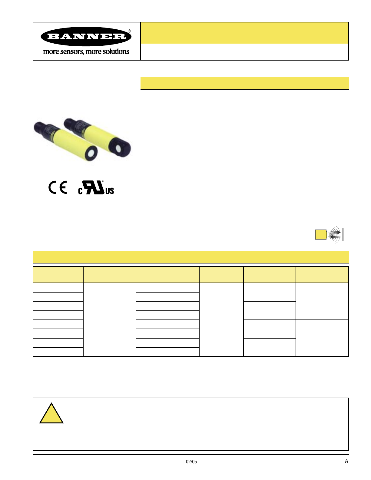
U-GAGE™ S18U Series Sensors with Analog Output
!
B
Aug 2013
18 mm Ultrasonic Sensors with TEACH-mode programming
Features
• Fast, easy-to-use TEACH-Mode programming; no potentiometer adjustments
Right-Angle Housing
Straight Housing
• Short dead zone
• Scalable output automatically distributes the output signal over the width of the
programmed sensing window
• Two bi-colored status LEDs
• Rugged encapsulated design for harsh environments
• Choose 2 meter or 9 meter unterminated cable, or 5-pin Euro-style QD connector
• Wide operating range of -20° to +60°C (-4° to +140°F)
• Choose either straight or right-angle housing
• Temperature compensation
• Selectable response times of 2.5 or 30 ms
• Select analog models with either 0-10V dc or 4-20 mA output
Models
Model
Number
S18UUA
S18UUAQ
S18UIA
S18UIAQ
S18UUAR
S18UUARQ
S18UIAR
S18UIARQ
* 9 m cables are available by adding suffix “W/30” to the model number of any cabled sensor (e.g., S18UUA W/30).
A model with a QD connector requires a mating cable; see page 10.
Sensing
Range
30 to 300 mm
(1.2" to 11.8")
Cable*
5-wire, 2 m (6.5') cable
5-pin Euro style QD
5-wire, 2 m (6.5') cable
5-pin Euro style QD
5-wire, 2 m (6.5') cable
5-pin Euro style QD
5-wire, 2 m (6.5') cable
5-pin Euro style QD
Supply
Voltage
10 to 30V dc
Output
0 to 10V dc
4 to 20 mA
0 to 10V dc
4 to 20 mA
Ultrasonic
Housing
Configuration
Straight
Right-Angle
Information about discrete models is available on Banner’s website: www.bannerengineering.com
WARNING . . .
Never use these products as sensing devices for personnel protection. Doing so could lead to serious injury or death.
These sensors do NOT include the self-checking redundant circuitry necessary to allow their use in personnel safety
applications. A sensor failure or malfunction can cause either an energized or de-energized sensor output condition.
Consult your current Banner Safety Products catalog for safety products which meet OSHA, ANSI and IEC standards for
personnel protection.
Printed in USA 02/05 P/N 110738 rev. A
Not To Be Used for Personnel Protection
Page 2
U-GAGE™ S18U Series Sensor — Analog Output
B
Principles of Operation
Ultrasonic sensors emit one or multiple pulses of ultrasonic energy, which travel
through the air at the speed of sound. A portion of this energy reflects off the target
and travels back to the sensor. The sensor measures the total time required for the
energy to reach the target and return to the sensor. The distance to the object is then
calculated using the following formula:
2
To improve accuracy, an ultrasonic sensor may average the results of several pulses
before outputting a new value.
ct
D =
Temperature Effects
The speed of sound is dependent upon the composition, pressure and temperature of
the gas in which it is traveling. For most ultrasonic applications, the composition and
pressure of the gas are relatively fixed, while the temperature may fluctuate.
D = distance from the sensor to the target
c = speed of sound in air
t = transit time for the ultrasonic pulse
In air, the speed of sound varies with temperature according to the following
approximation:
C
C
Or, in English units:
C
= 20 √273 + T
m/s
= 49 √460 + T
ft/s
C
F
= speed of sound in meters per second
m/s
TC = temperature in °C
C
= speed of sound in feet per second
ft/s
TF = temperature in °F
Temperature Compensation
Changes in air temperature affect the speed of sound, which in turn affects the distance
reading measured by the sensor. An increase in air temperature shifts both sensing
window limits closer to the sensor. Conversely, a decrease in air temperature shifts
both limits farther away from the sensor. This shift is approximately 3.5% of the limit
distance for a 20° C change in temperature.
The S18U series ultrasonic sensors are temperature compensated. This reduces the
error due to temperature by about 90%. The sensor will maintain its window limits to
within 1.8% over the -20° to +60° C range.
NOTES:
• Exposure to direct sunlight can affect the sensor’s ability to accurately compensate for
changes in temperature.
• If the sensor is measuring across a temperature gradient, the compensation will be
less effective.
• The temperature warmup drift upon power-up is less than 1.7% of the sensing
distance. After 10 minutes, the apparent distance will be within 0.3% of the actual
position. After 25 minutes, the sensing distance will be stable.
Banner Engineering Corp. • Minneapolis, MN U.S.A.
2 P/N 110738 rev. A
www.bannerengineering.com • Tel: 763.544.3164
Page 3
U-GAGE™ S18U Series Sensor — Analog Output
Power/
Signal Strength
LED
TEACH/
Output Indicator
LED
TEACH
Push Button
PWR OUT
TEACH
Minimum
Operating
Range
Near
Setpoint
Far
Setpoint
Maximum
Operating
Range
Target
Ta
rget
Ta
rget
Ta
rget
Dead Zone
Output
Power
Output
Power
Output
Power
ON:
Green
OFF
Output
Power
OFF
ON:
Green
ON:
Yellow
ON:
Green
OFF
ON:
Red
OFF
B
Sensor Programming
Two TEACH methods may be used to program the sensor:
• Teach individual minimum and maximum limits, or
• Use Auto-Window feature to center a sensing window around the taught position.
The sensor may be programmed either via its push button, or via a remote switch.
Remote programming also may be used to disable the push button, preventing
unauthorized personnel from adjusting the programming settings. To access this
feature, connect the gray wire of the sensor to 0 - 2V dc, with a remote programming
switch between the sensor and the voltage.
NOTE: The impedance of the Remote Teach input is 12 kΩ.
Programming is accomplished by following the sequence of input pulses (see
programming procedures starting on page 4). The duration of each pulse
(corresponding to a push button “click”), and the period between multiple pulses, are
defined as “T”:
0.04 seconds < T < 0.8 seconds
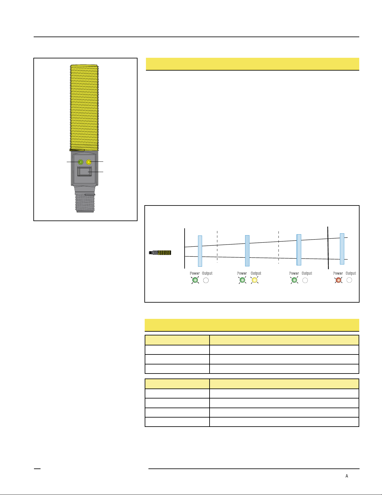
Figure 1. Sensor features
Figure 2. TEACH Interface
Status Indicators
Power ON/OFF LED Indicates
OFF Power is OFF.
ON Red Target is weak or outside sensing range.
ON Green Sensor is operating normally, good target.
Output/Teach LED Indicates
OFF Target is outside window limits.
Yellow Target is within window limits.
ON Red (solid) In Teach Mode, waiting for first limit.
ON Red (flashing) In Teach Mode, waiting for second limit.
Banner Engineering Corp. • Minneapolis, MN U.S.A.
www.bannerengineering.com • Tel: 763.544.3164
P/N 110738 rev. A 3
Page 4
U-GAGE™ S18U Series Sensor — Analog Output
4
Near
Window
Far
Window
20
Target Position
Analog Output (mA)
Positive
Slope
Current-Sourcing Models
0
Near
Window
Far
Window
10
Target Position
Analog Output (V dc)
Positive
Slope
Voltage-Sourcing Models
T
T T
T
T T
T T
T
T
T T
T
T T
T T
T
or
or
...
D
or
B
Teaching Minimum and Maximum Limits
General Notes on Programming
• The sensor will return to Run mode if the first Teach condition is not registered
within 120 seconds.
• After the first limit is taught, the sensor will remain in Program mode until the Teach
sequence is finished.
• To exit Program mode without saving any changes, press and hold the programming
push button > 2 seconds (before teaching the second limit). The sensor will revert to
the last saved limits.
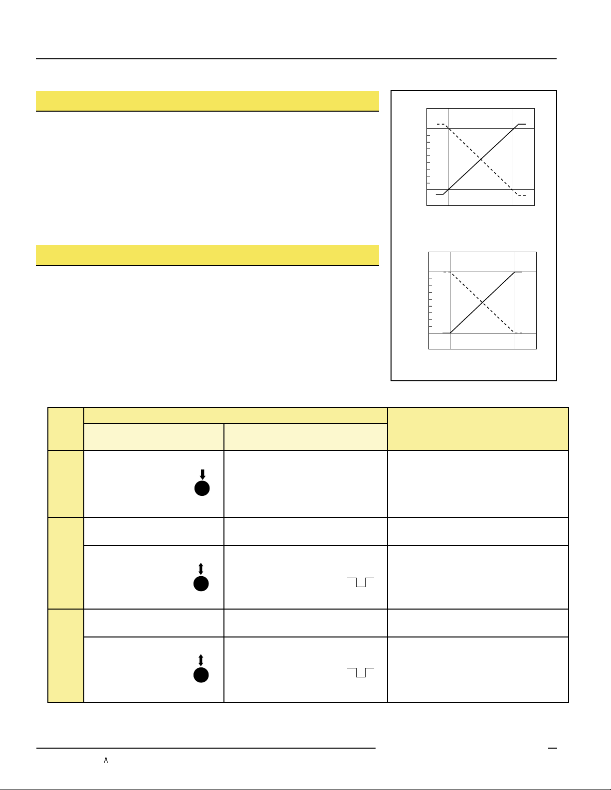
Analog Output Slope:
The U-GAGE S18U sensor may be programmed for either a positive or a negative
output slope, based on which limit is taught first (see Figure 3). If the Near limit is
taught first, the slope will be positive. If the Far limit is taught first, the slope will be
negative. Banner’s scalable output automatically distributes the output signal over the
width of the programmed sensing window.
In the event of signal loss, the analog output goes to 3.6 mA or 0V dc, which may be
used to trigger an alarm.
Procedure
0.04 < “click” < 0.8 sec.
• Push and hold the
push button
Mode
Programming
• Position the target for
the first limit
Teach
• “Click” the push button • Single-pulse the remote line
First Limit
• Position the target for
the second limit
Teach
• “Click” the push button • Single-pulse the remote line
Second Limit
Push Button
• No action required; sensor is ready for
1st limit teach
• Position the target for the first limit
• Position the target for the second limit
Remote Wire
0.04 sec. < T < 0.8 sec.
Figure 3. Analog output slope
Result
Output LED: ON Red
Power LED: ON Green (good signal) or
ON Red (no signal)
Power LED: Must be ON Green
Teach Accepted
(Sensor learns the 0V dc or 4 mA limit)
Output LED: Flashing Red
Teach Unacceptable
Output LED: ON Red
Power LED: Must be ON Green
Teach Accepted
(Sensor learns the 10V dc or 20 mA limit)
Output LED: Yellow or OFF
Teach Unacceptable
Output LED: Flashing Red
4 P/N 110738 rev. A
Banner Engineering Corp. • Minneapolis, MN U.S.A.
www.bannerengineering.com • Tel: 763.544.3164
Page 5

Push Button
T
T T
T
T T
T T
T
T
T T
T
T T
T T
T
or
or
...
D
or
B
0.04 < “click” < 0.8 sec.
U-GAGE™ S18U Series Sensor — Analog Output
Teaching Limits Using the Auto-Window Feature
Teaching the same limit twice for the same output automatically centers a 100 mm
window on the taught position.
General Notes on Programming
• The sensor will return to Run mode if the first Teach condition is not registered
within 120 seconds.
• After the first limit is taught, the sensor will remain in Program mode until the Teach
sequence is finished.
• To exit Program mode without saving any changes, press and hold the programming
push button > 2 seconds (before teaching the second limit). The sensor will revert to
the last saved limits.
• Using this procedure the analog output will be centered on the taught position at
approximately 5V dc or 12 mA.
Procedure
Remote Wire
0.04 sec. < T < 0.8 sec.
Result
• Push and hold the
push button
Mode
• No action required; sensor is ready for
first limit teach
Output LED: ON Red
Power LED: ON Green (good signal) or
ON Red (no signal)
Programming
• Position the target for
the center of the window
• “Click” the push button • Single-pulse the remote line
Teach Limit
• Without moving the
target, “click” the
Limit
Re-Teach
push button again
• Position the target for the center of the
window
• Without moving the target,
single-pulse the remote line
again
Power LED: Must be ON Green
Teach Accepted
Output LED: Flashing Red
Teach Unacceptable
Output LED: ON Red
Teach Accepted
Output LED: Yellow or OFF
Teach Unacceptable
Output LED: Flashing Red
Banner Engineering Corp. • Minneapolis, MN U.S.A.
www.bannerengineering.com • Tel: 763.544.3164
P/N 110738 rev. A 5
Page 6

U-GAGE™ S18U Series Sensor — Analog Output
TTT
T T
T T T
T T
T T
T
T T
T T
T
B
Push Button Lockout
Enables or disables the push button to prevent unauthorized adjustment of the program
settings.
Procedure
Push Button
Remote Wire
0.04 sec. < T < 0.8 sec.
Result
• Not available via push button • Four-pulse the remote line
Push Button
Enable/Disable
• Push buttons are either enabled or disabled,
depending on previous condition.
6 P/N 110738 rev. A
Banner Engineering Corp. • Minneapolis, MN U.S.A.
www.bannerengineering.com • Tel: 763.544.3164
Page 7

U-GAGE™ S18U Series Sensor — Analog Output
B
Specifications
Sensing Range
Supply Voltage
Ultrasonic Frequency
Supply Protection Circuitry
Output Configuration Analog Output: 0 to 10V dc or 4 to 20 mA, depending on model
Output Protection
Output Ratings Analog Voltage Output: 2.5 kΩ minimum load resistance
Output Response Time
(for a 95% step change)
Delay at Power-Up
Temperature Effect
Linearity* 2.5 ms response: ±1 mm 30 ms response: ± 0.5 mm
Resolution* 2.5 ms response: 1 mm 30 ms response: 0.5 mm
Minimum Window Size
Adjustments Sensing window limits: TEACH-Mode programming of near and far window limits may be set using the
Indicators Range Indicator (Red/Green) Green — Target is within sensing range
Remote TEACH Input Impedance: 12 kΩ
Construction Threaded Barrel: Thermoplastic polyester Push Button Housing: ABS/PC
Operating Conditions Temperature: -20° to +60° C (-4° to +140° F) Maximum relative humidity: 100%
Connections
Environmental Rating
Vibration and Mechanical
Shock
Temperature Warmup Drift
Application Notes
Certifications
30 to 300 mm (1.2" to 11.8")
10 to 30V dc (10% maximum ripple); 65 mA max. (exclusive of load), 40 mA typical @ 25V input
300 kHz, rep. rate 2.5 ms
Protected against reverse polarity and transient voltages
Protected against short circuit conditions
Minimum supply for a full 10V output is 12V dc (for supply voltages between 10
and 12, V out max is at least V supply -2)
Analog Current Output: 1 kΩ max @ 24V input
Max load resistance = (Vcc-4)/0.02 ohms
For current output (4-20 mA) models, ideal results are achieved when the total load resistance
R = [(Vin – 3)/0.020]Ω. Example, at Vin = 24V dc, R ≈ 1 kΩ (1 watt). A worst-case shift of 1% of sensing
distance is caused by operating the sensor at Vin = 30V dc and R = 0 Ω.
2.5 milliseconds: Black wire at 5-30V dc
30 milliseconds: Black wire at 0-2V dc (or open)
Consult factory for other response speed options
300 milliseconds
0.02% of distance/ °C
5 mm
push button or remotely via TEACH input (see page 3).
Red — Target is outside sensing range
OFF — Sensing power is OFF
Teach/Output Indicator (Yellow/Red) Yellow — Target is within taught limits
OFF — Target is outside taught window limits
Red — Sensor is in TEACH mode
Push Button: Santoprene Lightpipes: Acrylic
2 m (6.5') or 9 m (30') shielded 5-conductor (with drain) PVC jacketed attached cable or 5-pin
Euro-style quick-disconnect (see page 10 for quick-disconnect cable options)
Leakproof design is rated IEC IP67; NEMA 6P
All models meet Mil. Std. 202F requirements method 201A (vibration: 10 to 60 Hz max., double amplitude
0.06", maximum acceleration 10G). Also meets IEC 947-5-2 requirements: 30G 11 ms duration, half sine
wave.
Less than 1.7% of sensing distance upon power-up (see Temperature Compensation, page 2)
Objects passing inside the specified near limit may produce a false response.
* Linearity and resolution are specified using a 50 mm x 50 mm (2" x 2") aluminum plate at 22°C under fixed sensing conditions.
Banner Engineering Corp. • Minneapolis, MN U.S.A.
www.bannerengineering.com • Tel: 763.544.3164
P/N 110738 rev. A 7
Page 8

U-GAGE™ S18U Series Sensor — Analog Output
Lateral Distance
-5 mm
-10 mm
-15 mm
5 mm
0
10 mm
15 mm
20 mm
-20 mm
0 100 mm 150 mm50 mm 200 mm 250 mm 300 mm
Sensing Distance
2.25 mm rod
8 mm rod
50 mm x 50 mm
Target Rotation
Sensing Distance
-5°
-10°
-15°
5°
0
10°
15°
0 50 mm 100 mm 150 mm 200 mm 250 mm 300 mm
Aluminum target used: 50 mm x 50 mm
bn
shield
bk
gy
bn
bu
wh
+10 - 30V dc
shield
shield
Remote Teach
0 - 2V dc
4 - 20 mA or
0 - 10V dc
5 - 30V dc (fast)
0 - 2V dc (slow)
bn
bu
+10 - 30V dc
4 - 20 mA or
0 - 10V dc
wh
gy
0 - 2V dc
bk
5 - 30V dc (fast)
0 - 2V dc (slow)
Remote Teach
B
Sensor Response Curves
Effective Beam Pattern (Typical)
Cabled Models QD Models
Maximum Target Rotation Angle
Hookups
NOTE: It is recommended that the shield wire be connected to earth ground or DC common.
8 P/N 110738 rev. A
Banner Engineering Corp. • Minneapolis, MN U.S.A.
www.bannerengineering.com • Tel: 763.544.3164
Page 9

53.8 mm
(2.12")
90.9 mm
(3.58")
95.1 mm
(3.75")
8.5 mm
(0.33")
58.0 mm
(2.29")
85.1 mm
(3.35")
53.8 mm
(2.12")
80.8 mm
(3.18")
8.5 mm
(0.33")
18.1 mm
(0.71")
18.0 mm
(0.71")
18.0 mm
(0.71")
58.0 mm
(2.29")
3.6 mm
(0.14")
10.6 mm
(0.42")
10.6 mm
(0.42")
Tr
ansducer
6.0 mm (0.24")
6.0 mm (0.24")
Tr
ansducer
B
U-GAGE™ S18U Series Sensor — Analog Output
Dimensions
Straight Housing
Cabled Models QD Models
Right-Angle Housing
Cabled Models QD Models
Banner Engineering Corp. • Minneapolis, MN U.S.A.
www.bannerengineering.com • Tel: 763.544.3164
P/N 110738 rev. A 9
Page 10

U-GAGE™ S18U Series Sensor — Analog Output
White
Blue
Black
Brown
Gray
M12 x 1
ø 15 mm
(0.6")
44 mm max.
(1.7")
38 mm max.
(1.5")
M12 x 1
ø 15 mm
(0.6")
38 mm max.
(1.5")
B
Accessories
Quick-Disconnect Cables
Style Model Length Dimensions Pinout
5-pin
Euro-style
straight, with
shield
5-pin
Euro-style
right-angle,
with shield
MQDEC2-506
MQDEC2-515
MQDEC2-530
MQDEC2-506RA
MQDEC2-515RA
MQDEC2-530RA
2 m (6.5')
5 m (15')
9 m (30')
2 m (6.5')
5 m (15')
9 m (30')
Banner Engineering Corp. • Minneapolis, MN U.S.A.
www.bannerengineering.com • Tel: 763.544.3164
10 P/N 110738 rev. A
Page 11

U-GAGE™ S18U Series Sensor — Analog Output
18.5 mm
(0.73")
25.4 mm
(1.00")
41 mm
(1.6")
46 mm
(1.8")
30°
30 mm
(1.2")
R 24.2 mm
(0.95")
ø 4.6 mm*
(0.18")
4.6 mm*
(0.18")
* Use 4 mm (#8) screws
to mount bracket.
Drill screw holes
24.2 mm (0.95") apart.
7.6 mm
(0.30")
36.0 mm
(1.42")
50.8 mm
(2.00")
42.0 mm
(1.65")
22.9 mm
(0.9")
25.4 mm
(1.00")
10.6 mm
(0.42")
M18 x 1
internal
thread
50.8 mm
(2.0")
66.0 mm
(2.60")
41.7 mm
(1.64")
24.6 mm
(0.97")
20.8 mm
(0.82")
16.0 mm
(0.63 ")
45.2 mm
(1.78")
ø18.3 mm
(0.72")
2.7 mm
(0.10")
2.7 mm
(0.10")
27.2 mm
(1.07")
ø20.3 mm
(0.80")
ø30.5 mm
(1.20")
R2.5 mm
(0.10")
60º
60º
46.7 mm
(1.84")
9.7 mm
(0.38")
71.1 mm
(2.80")
20.3 mm
(0.80")
4X 6.9 mm
(0.27")
20.3 mm
(0.80")
33.8 mm
(1.33")
60º
25.4 mm
(1.00")
25.4 mm
(1.00")
8.1 mm
(0.32")
41.7 mm
(1.64")
20.8 mm
(0.82")
6X #10-32 Thru
ø30.5 mm
(1.20")
63.5 mm
(2.50")
SMB18UR Top
SMB18UR Bottom
B
Mounting Brackets
SMB18A
SMB18UR
• 12-gauge, stainless steel, right-angle
mounting bracket with a curved mounting
slot for versatility and orientation
• Clearance for M4 (#8) hardware
• 2-piece universal 18 mm swivel bracket
• 300 series stainless steel
• Includes stainless steel swivel locking
hardware
SMB18SF
• 18 mm swivel bracket
• Black thermoplastic polyester
• Includes stainless steel hardware
Banner Engineering Corp. • Minneapolis, MN U.S.A.
www.bannerengineering.com • Tel: 763.544.3164
P/N 110738 rev. A 11
Page 12

U-GAGE™ S18U Series Sensor — Analog Output
B
Banner Engineering Corp Limited Warranty
Banner Engineering Corp. warrants its products to be free from defects in material and workmanship for one year following the date of shipment. Banner
Engineering Corp. will repair or replace, free of charge, any product of its manufacture which, at the time it is returned to the factory, is found to have been
defective during the warranty period. This warranty does not cover damage or liability for misuse, abuse, or the improper application or installation of the
Banner product.
THIS LIMITED WARRANTY IS EXCLUSIVE AND IN LIEU OF ALL OTHER WARRANTIES WHETHER EXPRESS OR IMPLIED (INCLUDING, WITHOUT
LIMITATION, ANY WARRANTY OF MERCHANTABILITY OR FITNESS FOR A PARTICULAR PURPOSE), AND WHETHER ARISING UNDER COURSE OF
PERFORMANCE, COURSE OF DEALING OR TRADE USAGE.
This Warranty is exclusive and limited to repair or, at the discretion of Banner Engineering Corp., replacement. IN NO EVENT SHALL BANNER
ENGINEERING CORP. BE LIABLE TO BUYER OR ANY OTHER PERSON OR ENTITY FOR ANY EXTRA COSTS, EXPENSES, LOSSES, LOSS OF
PROFITS, OR ANY INCIDENTAL, CONSEQUENTIAL OR SPECIAL DAMAGES RESULTING FROM ANY PRODUCT DEFECT OR FROM THE USE OR
INABILITY TO USE THE PRODUCT, WHETHER ARISING IN CONTRACT OR WARRANTY, STATUTE, TORT, STRICT LIABILITY, NEGLIGENCE, OR
OTHERWISE.
Banner Engineering Corp. reserves the right to change, modify or improve the design of the product without assuming any obligations or liabilities relating to
any product previously manufactured by Banner Engineering Corp.
P/N 110738 rev A.
Banner Engineering Corp., 9714 Tenth Ave. No., Minneapolis, MN USA 55441 • Phone: 763.544.3164 • www.bannerengineering.com • Email: sensors@bannerengineering.com
WARRANTY: Banner Engineering Corp. warrants its products to be free from defects for
one year. Banner Engineering Corp. will repair or replace, free of charge, any product of its
manufacture found to be defective at the time it is returned to the factory during the warranty
period. This warranty does not cover damage or liability for the improper application of
Banner products. This warranty is in lieu of any other warranty either expressed or implied.
 Loading...