

Page 1
S18 Sensors – dc-Voltage Series
!
78.0 mm*
(3.07")
37.0 mm
(1.46")
Yellow LED
Output Indicator
Jam Nuts
(2 Provided)
18 x 1 mm
Thread
Green LED
Power Indicator
*Polarized retro and fixed-field models = 83.8 mm (3.30")
59.2 mm*
(2.33")
Yellow LED
Output Indicator
37.0 mm
(1.46")
Jam Nuts
(2 Provided)
18 x 1 mm
Thread
2 m
(6.5') Cable
Green LED
Power Indicator
*Polarized retro and fixed-field models = 65.0 mm (2.56")
P
LISTED
R
bn
bu
wh
bk
+
10 - 30V dc
–
Load
Load
bu
bn
wh
bk
10 - 30V dc
Load
Alarm
+
–
bn
bu
10-30V dc
+
–
10 - 30V dc
No Connection
bu
bk
bn
wh
+
–
bu
bn
wh
bk
+
10 - 30V dc
–
Load
Load
bn
bu
wh
bk
10 - 30V dc
Load
Alarm
+
–
Installation
Self-contained, dc-operated sensors
Additional information on this product is immediately available online at www.bannerengineering.com/116159
View or download additional information, including excess gain curves, beam patterns and accessories.
For further assistance, contact a Banner Engineering Applications Engineer at (763) 544-3164 or (888) 373-6767.
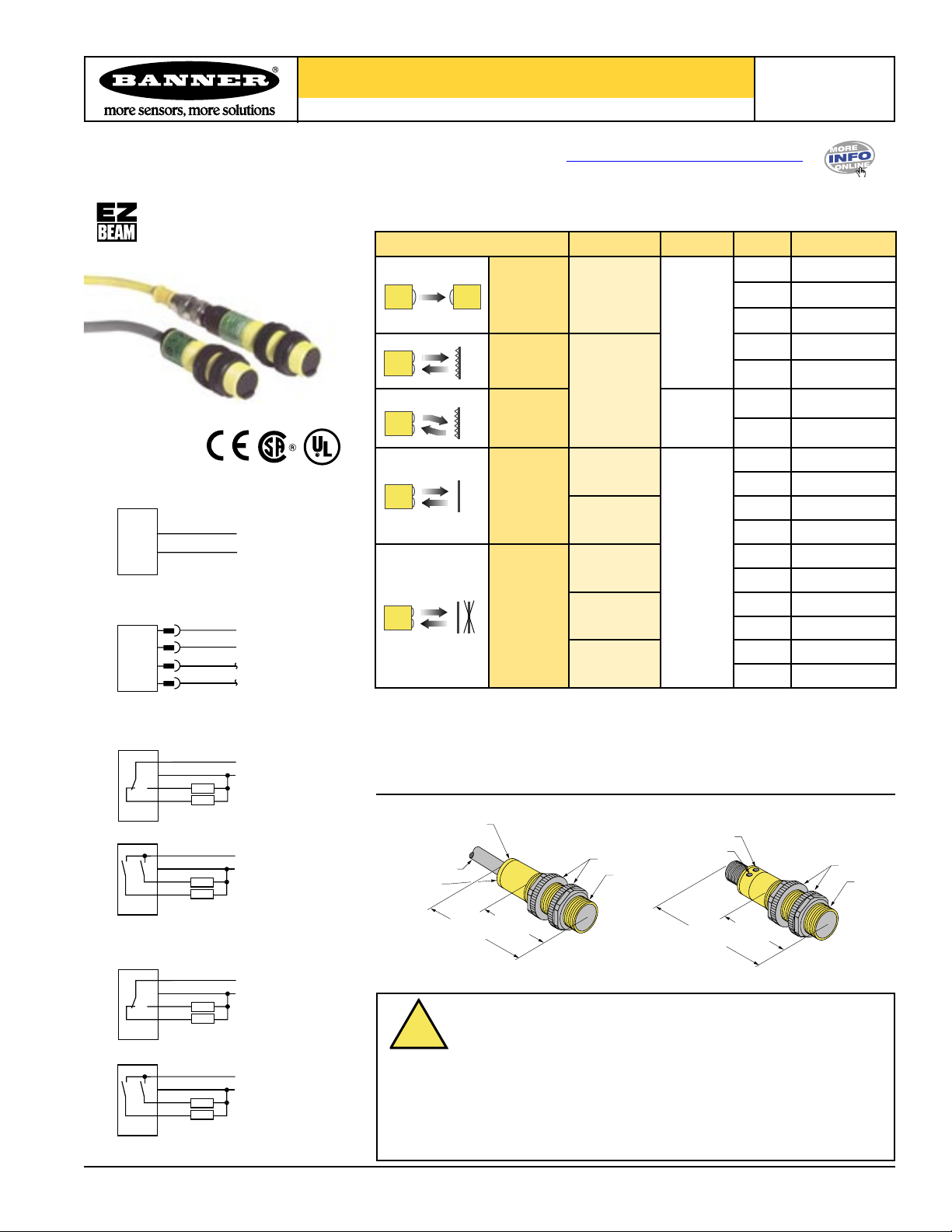
Sensing Mode Range LED Output Model*
– S186E
Cabled Emitters
QD Emitters
NPN (Sinking) Outputs
Standard Hookup
Opposed
20 m
(66')
Infrared
950 nm
Retroreflective
†
2 m
Polarized
Retroreflective
(79")
†
Visible
Red
680 nm
100 mm
(4")
Diffuse
300 mm
(12")
Infrared
880 nm
Fixed
Field
25 mm (1")
cutoff
50 mm (2")
cutoff
100 mm (4")
cutoff
* Standard 2 m (6.5') cable models are listed.
• 9 m (30') cable: add suffix “W/30” (e.g., S186E W/30).
• 4-pin Euro-style QD models: add suffix “Q” (e.g., S186EQ). A model with a QD connector requires a
mating cable.
† Use polarized models when shiny objects will be sensed.
NPN
PNP
NPN
PNP
NPN
PNP
NPN
PNP
NPN
PNP
NPN
PNP
NPN
PNP
NPN
PNP
Guide
S18SN6R
S18SP6R
S18SN6L
S18SP6L
S18SN6LP
S18SP6LP
S18SN6D
S18SP6D
S18SN6DL
S18SP6DL
S18SN6FF25
S18SP6FF25
S18SN6FF50
S18SP6FF50
S18SN6FF100
S18SP6FF100
PNP (Sourcing) Outputs
Printed in USA 10/04 P/N 116159
NOTE: QD hookups are functionally identical.
Alarm Hookup
Standard Hookup
Alarm Hookup
Dimensions
Cabled Models
WARNING . . .
Never use these products as sensing devices for personnel protection.
Doing so could lead to serious injury or death. These sensors do
NOT include the self-checking redundant circuitry necessary to allow their use in
personnel safety applications. A sensor failure or malfunction can cause either
an energized or de-energized sensor output condition. Consult your current
Banner Safety Products catalog for safety products which meet OSHA, ANSI and
IEC standards for personnel protection.
Not To Be Used for Personnel Protection
QD Models
Page 2
LISTED
R
38 mm max.
(1.5")
M12 x 1
ø 15 mm
(0.6")
38 mm max.
(1.5")
M12 x 1
ø 15 mm
(0.6")
44 mm max.
(1.7")
White Wire
Brown Wire
Black Wire
Blue Wire
S18 Sensors – dc-Voltage Series
Specifications
Supply Voltage and Current (exclusive of load current): 10 to 30V dc (10% max.
ripple); supply current (exclusive of load current):
Emitters, Non-Polarized Retro, Diffuse: 25 mA
Receivers: 20 mA
Polarized Retroreflective: 30 mA
Fixed-Field: 35 mA
Supply Protection Circuitry
Protected against reverse polarity and transient voltages
Output Configuration
SPDT solid-state dc switch; Choose NPN (current sinking) or PNP (current
sourcing) models
Light Operate: N.O. output conducts when sensor sees its own (or the
emitter’s) modulated light
Dark Operate: N.C. output conducts when the sensor sees dark; the N.C.
(normally closed) output may be wired as a normally open
marginal signal alarm output, depending upon hookup to power
supply (U.S. patent 5087838)
Output Rating
150 mA maximum (each) in standard hookup. When wired for alarm output, the
total load may not exceed 150 mA.
OFF-state leakage current: < 1 microamp @ 30V dc
ON-state saturation voltage: < 1V at 10 mA dc; < 1.5V at 150 mA dc
Output Protection Circuitry
Protected against false pulse on power-up and continuous overload or short
circuit of outputs
Output Response Time
Opposed mode: 3 ms ON, 1.5 ms OFF
Retro, Fixed-Field and Diffuse: 3 ms ON and OFF
NOTE: 100 ms delay on power-up; outputs do not conduct during this time.
Repeatability
Opposed mode: 375 µs
Retro, Fixed-Field and Diffuse: 750 µs
Repeatability and response are independent of signal strength.
Indicators
Two LEDs (Green and Yellow)
Green ON steady: power to sensor is ON
Green flashing: output is overloaded
Yellow ON steady: N.O. output is conducting
Yellow flashing: excess gain marginal (1 to 1.5x) in light condition
Construction
PBT polyester housing; polycarbonate (opposed mode) or acrylic lens
Environmental Rating
Leakproof design rated NEMA 6P, DIN 40050 (IP69K)
Connections
2 m (6.5') or 9 m (30') attached cable, or 4-pin Euro-style quick-disconnect
fitting
Operating Conditions
Temperature: -40° to +70°C (-40° to +158°F)
Maximum relative humidity: 90% at 50°C (non-condensing)
Vibration and Mechanical Shock
All models meet Mil. Std. 202F requirements. Method 201A (Vibration;
frequency 10 to 60 Hz, max., double amplitude 0.06" acceleration 10G).
Method 213B conditions H&I (Shock: 75G with unit operating; 100G for
non-operation)
Certifications
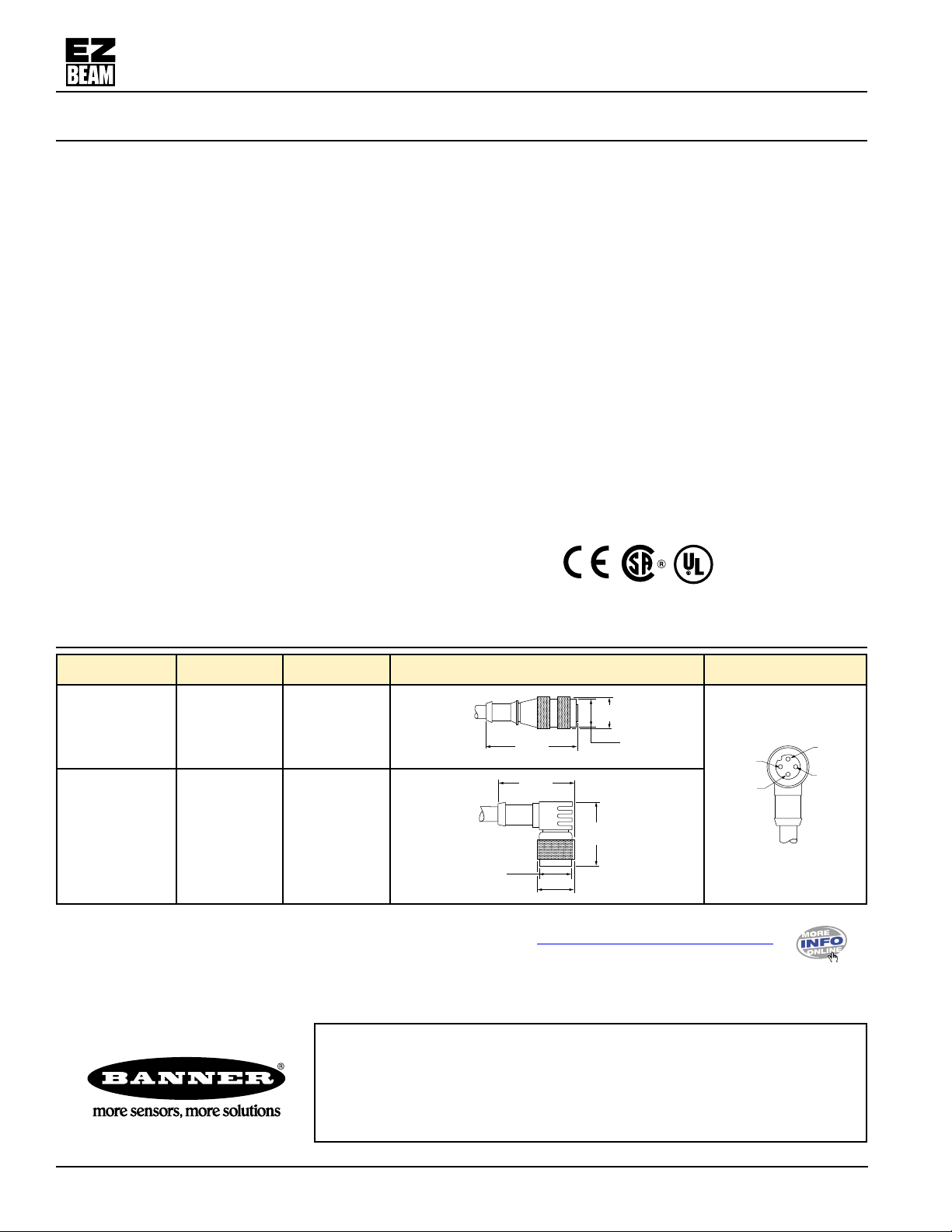
Quick-Disconnect (QD) Cables
Style Model Length Dimensions Pin-Out
4-pin
Euro-style
Straight
4-pin
Euro-style
Right-angle
MQDC-406
MQDC-415
MQDC-430
MQDC-406RA
MQDC-415RA
MQDC-430RA
Additional information on this product is immediately available online at www.bannerengineering.com/116159
View or download additional information, including excess gain curves, beam patterns and accessories.
For further assistance, contact a Banner Engineering Applications Engineer at (763) 544-3164 or (888) 373-6767.
2 m (6.5')
5 m (15')
9 m (30')
2 m (6.5')
5 m (15')
9 m (30')
WARRANTY: Banner Engineering Corp. warrants its products to be free from defects for
one year. Banner Engineering Corp. will repair or replace, free of charge, any product of its
manufacture found to be defective at the time it is returned to the factory during the warranty
period. This warranty does not cover damage or liability for the improper application of
Banner products. This warranty is in lieu of any other warranty either expressed or implied.
P/N 116159
Banner Engineering Corp., 9714 Tenth Ave. No., Minneapolis, MN USA 55441 • Phone: 763.544.3164 • www.bannerengineering.com • Email: sensors@bannerengineering.com
 Loading...