

Page 1
1
10
100
1 m
3.3 ft
10 m
33 ft
100 m
330 ft
.1 m
.33 ft
1000
DISTANCE
EXCESS GAIN
S12 Series
Opposed Mode
25 m
82 ft
20 m
66 ft
15 m
49 ft
10 m
32 ft
5 m
16 ft
0
0
500 mm
1000 mm
1500 mm
500 mm
1000 mm
1500 mm
0
20 in
40 in
60 in
20 in
40 in
60 in
DISTANCE
S12 Series
Opposed Mode
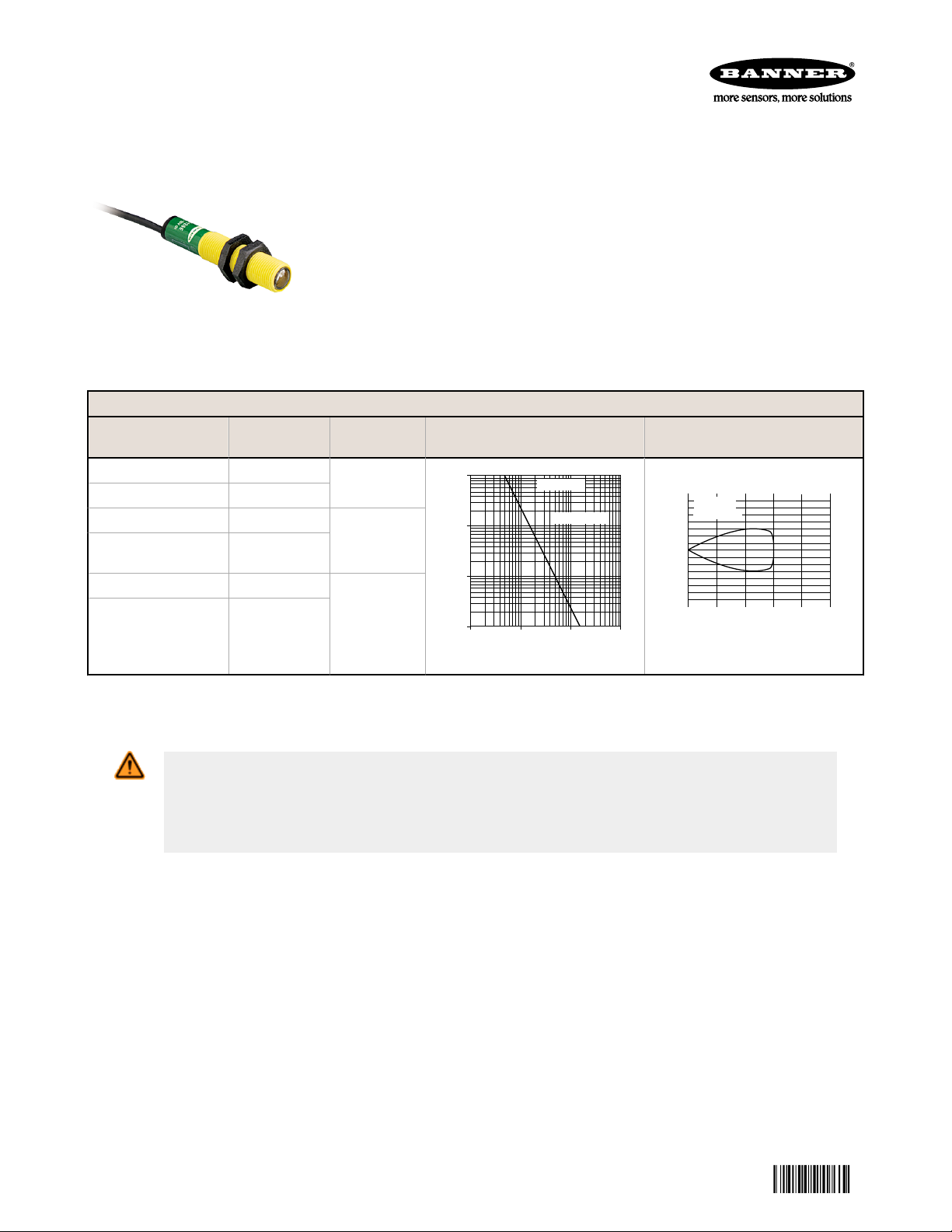
EZ-BEAM S12 Series Opposed-Mode Sensor
34501
Pairs
Datasheet
• Economical opposed-mode (beam-break) sensor pairs in 12-millimeter
diameter barrel-style housings
• Sensing range of 15 meters (50 feet)
• Totally self-contained; 10 to 30 V dc operation
• Complementary outputs: one normally open, one normally closed;
choice of NPN (sinking) or PNP (sourcing) configuration, 100 mA max.
(continuous)
• One output may be used as a marginal signal alarm
• LED status indicators for Power On, Output Overload, Object Sensed,
and Low Gain conditions
Visible Red, 680 nm
Models Cable
S126E Emitter 2 m (6.5 ft)
S126EQP Emitter 4-Pin Pico QD
S12SN6R Receiver 2 m (6.5 ft)
S12SN6RQP
Receiver
4-Pin Pico QD
S12SP6R Receiver 2 m (6.5 ft)
Output
Type
-
NPN
Excess Gain
Beam Pattern (Effective
beam: 8.1 mm)
S12SP6RQP
Receiver
4-Pin Pico QD
PNP
To order 9 m (30 ft) cable models, add the suffix “W/30” to the model number of any cabled sensor (e.g. - S12SN6R W/
30). Models with a QD connector requires an accessory mating cable.
WARNING: Not To Be Used for Personnel Protection
Never use this device as a sensing device for personnel protection. Doing so could lead to
serious injury or death. This device does not include the self-checking redundant circuitry necessary
to allow its use in personnel safety applications. A sensor failure or malfunction can cause either an
energized or de-energized sensor output condition.
Original Document
34501 Rev. B
27 March 2014
Page 2
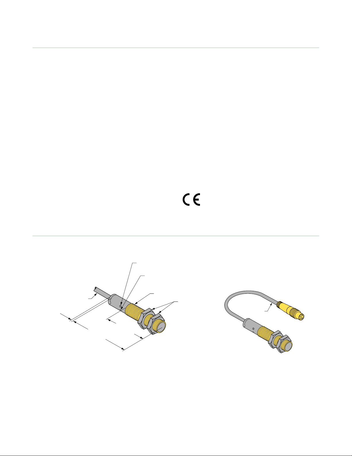
59.9 mm
(2.36")
4.1 mm
(0.16")
Amber LED
Output Indicator
38 mm
(1.5")
Jam Nuts
(Provided)
12 x 1 mm Thread
2 m
(6.5') Cable
Green LED
Power Indicator
150 mm
(6") Pigtail
EZ-BEAM S12 Series Opposed-Mode Sensor Pairs
Specifications
Supply Voltage and Current
10 to 30 V dc (10% maximum ripple)
Supply current (exclusive of load current): Opposed Mode Emitters: 25
mA; Opposed Mode Receivers: 20 mA
Supply Protection Circuitry
Protected against reverse polarity and transient voltages
Output Configuration
SPDT (complementary) solid-state dc switch; choose NPN (current
sinking) or PNP (current sourcing) models.
Light operate: N.O. output conducts when the sensor sees the emitter’s
modulated light
Dark operate: N.C. output conducts when the sensor sees dark; The
N.C. (normally closed) output may be wired as a normally open
marginal signal alarm output, depending upon hookup to the power
supply (U.S. patent 5087838)
Output Rating
100 mA maximum (each) in standard hookup; when wired for alarm
output, the total load may not exceed 100 mA
Off-state leakage current < 1 microamp at 30 V dc
On-state saturation voltage < 1 V at 10 mA dc and < 1.5 V at 150 mA
dc
Output Protection Circuitry
Protected against false pulse on power-up and continuous overload or
short circuit of outputs
Output Response Time
3 milliseconds ON, 1.5 milliseconds OFF
100 millisecond delay on power-up; outputs are non-conducting during
this time
Repeatability
375 microseconds; repeatability and response are independent of
signal strength
Indicators
Receivers have two LEDs: green and amber
Green solid: power to sensor is “on”
Green flashing: output is overloaded (dc models only)
Amber solid: normally open output is conducting
Amber flashing: excess gain marginal (1–1.5x) in light condition
Construction
reinforced thermoplastic polyester housings; polycarbonate lenses;
polyurethane end cap
Environmental Rating
Leakproof design rated NEMA 6P (IEC IP67)
Connections
2 m (6.5 ft) or 9 m (30 ft) attached PVC-covered 4-wire cable, or a 4pin Pico-style QD
Operating Conditions
Temperature: –40 °C to 70 °C (–40 °F to 158 °F)
Maximum relative humidity: 90% at 50 °C (non-condensing)
Vibration and Mechanical Shock
Meets Mil. Std. 202F requirements.
Method 201A (Vibration: frequency 10 to 60 Hz, max., double
amplitude 0.06-inch acceleration 10G).
Method 213B conditions H&I (Shock: 75G with unit operating; 100G for
non-operation).
Certifications
Dimensions
Figure 1. Cabled Models
2 www.bannerengineering.com - tel: 763-544-3164 P/N 34501 Rev. B
Figure 2. Pigtail Quick Disconnect Models
Page 3

3
1
−
+
4
2
Load
Load
Load
Load
10–30 V dc
1
3
−
+
4
2
Load
Load
10–30 V dc
10–30 V dc
3
1
−
+
4
2
Alarm
Load
10–30 V dc
1
3
−
+
4
2
Alarm
Load
+
−
10–30 V dc
1
3
1
3
+
−
10–30 V dc
4
2
not used
not used
R 5.1 mm
(0.20")
20
10
ø 4.6 mm
(0.18")
R 3.1 mm
(0.12")
R 24.1 mm
(0.95")
Slot 4.6 mm
(0.18")
12.7 mm
(0.50")
ø 12.3 mm
(0.49")
25.4 mm
(1.00")
42.9 mm
(1.69")
38.1 mm
(1.50")
12.3 mm
(0.49")
EZ-BEAM S12 Series Opposed-Mode Sensor Pairs
Wiring Diagrams
Receivers with NPN Outputs (Standard) Receivers with PNP Outputs (Standard) Key
Receivers with NPN Outputs (Alarm) Receivers with PNP Outputs (Alarm) Key
1 - Brown
2 - White
3 - Blue
4 - Black
1 - Brown
2 - White
3 - Blue
4 - Black
Emitters with Attached Cable Emitters with Quick Disconnect Key
Accessories
Brackets
SMB12MM
• 12-gauge, stainless steel, right-angle mounting bracket for
barrel-style sensors with 12 mm threads
• Curved mounting slot allows the bracket ±10° of lateral
movement
• Mounting holes accommodate #8 hardware
Hole center spacing: A to B = 26.0
Hole size: A = ø 4.6, B = 12.8 x 4.6, C= ø 12.3
1 - Brown
2 - White
3 - Blue
4 - Black
Aperture Kits. SP12 sensors may be fitted with apertures that narrow or shape the effective beam of the sensor and
protect the sensor’s lens. These apertures are rectangular or circular thread-on water-tight parts. Use of apertures with
SP12 high-gain sensors makes it possible to create very narrow, concentrated sensing beams for precision sensing
applications.
P/N 34501 Rev. B www.bannerengineering.com - tel: 763-544-3164 3
Page 4

ø 9.0
32 Typ.
4
3
1
2
ø 10.9
29 Typ.
15 Typ.
Model Description Dimensions
AP12SC
AP12SR
4-Pin Snap-on M8/Pico-Style Cordsets
Model Length Style Dimensions Pinout
PKG4-2 2.00 m (6.56 ft) Straight
PKW4Z-2 2.00 m (6.56 ft) Right-Angle
EZ-BEAM S12 Series Opposed-Mode Sensor Pairs
Includes lens, o-ring, thread-on housing, and 3 circular apertures
with openings of:
• 0.5 mm (0.02 inch) diameter
• 1.0 mm (0.04 inch) diameter
• 2.5 mm (0.10 inch) diameter
Includes lens, o-ring, thread-on housing, and 3 rectangular
apertures with openings of:
• 0.5 mm (0.02 inch) wide
• 1.0 mm (0.04 inch) wide
• 2.5 mm (0.10 inch) wide
1 = Brown
2 = White
3 = Blue
4 = Black
Banner Engineering Corp Limited Warranty
Banner Engineering Corp. warrants its products to be free from defects in material and workmanship for one year following
the date of shipment. Banner Engineering Corp. will repair or replace, free of charge, any product of its manufacture
which, at the time it is returned to the factory, is found to have been defective during the warranty period. This warranty
does not cover damage or liability for misuse, abuse, or the improper application or installation of the Banner product.
THIS LIMITED WARRANTY IS EXCLUSIVE AND IN LIEU OF ALL OTHER WARRANTIES WHETHER EXPRESS OR
IMPLIED (INCLUDING, WITHOUT LIMITATION, ANY WARRANTY OF MERCHANTABILITY OR FITNESS FOR A
PARTICULAR PURPOSE), AND WHETHER ARISING UNDER COURSE OF PERFORMANCE, COURSE OF DEALING OR
TRADE USAGE.
This Warranty is exclusive and limited to repair or, at the discretion of Banner Engineering Corp., replacement. IN NO
EVENT SHALL BANNER ENGINEERING CORP. BE LIABLE TO BUYER OR ANY OTHER PERSON OR ENTITY FOR
ANY EXTRA COSTS, EXPENSES, LOSSES, LOSS OF PROFITS, OR ANY INCIDENTAL, CONSEQUENTIAL OR
SPECIAL DAMAGES RESULTING FROM ANY PRODUCT DEFECT OR FROM THE USE OR INABILITY TO USE THE
PRODUCT, WHETHER ARISING IN CONTRACT OR WARRANTY, STATUTE, TORT, STRICT LIABILITY,
NEGLIGENCE, OR OTHERWISE.
Banner Engineering Corp. reserves the right to change, modify or improve the design of the product without assuming any
obligations or liabilities relating to any product previously manufactured by Banner Engineering Corp.
www.bannerengineering.com - tel: 763-544-3164
 Loading...