

Page 1
-6
+6
-4.8
-4
+4
mm
+4.8
11-12
23-24
Break (91N/156N)
11-12
23-24
S2S1
Tension
Set Point
133N/228N
Latch
Pull (175N/300N)
Latch
Safety
Monitor
Safety
Monitor
1211
2423
1211
2423
-6
+6
-4.8
-4
-3
+4
+3
mm
+4.8
11-12
23-24
Break (91N/156N)
11-12
23-24
2-3
S2S1
Tension
Set Point
133N/228N
Latch
Pull (175N/300N)
Latch
Safety
Monitor
Safety
Monitor
Aux.
Aux.
1211
2423
1211
2423
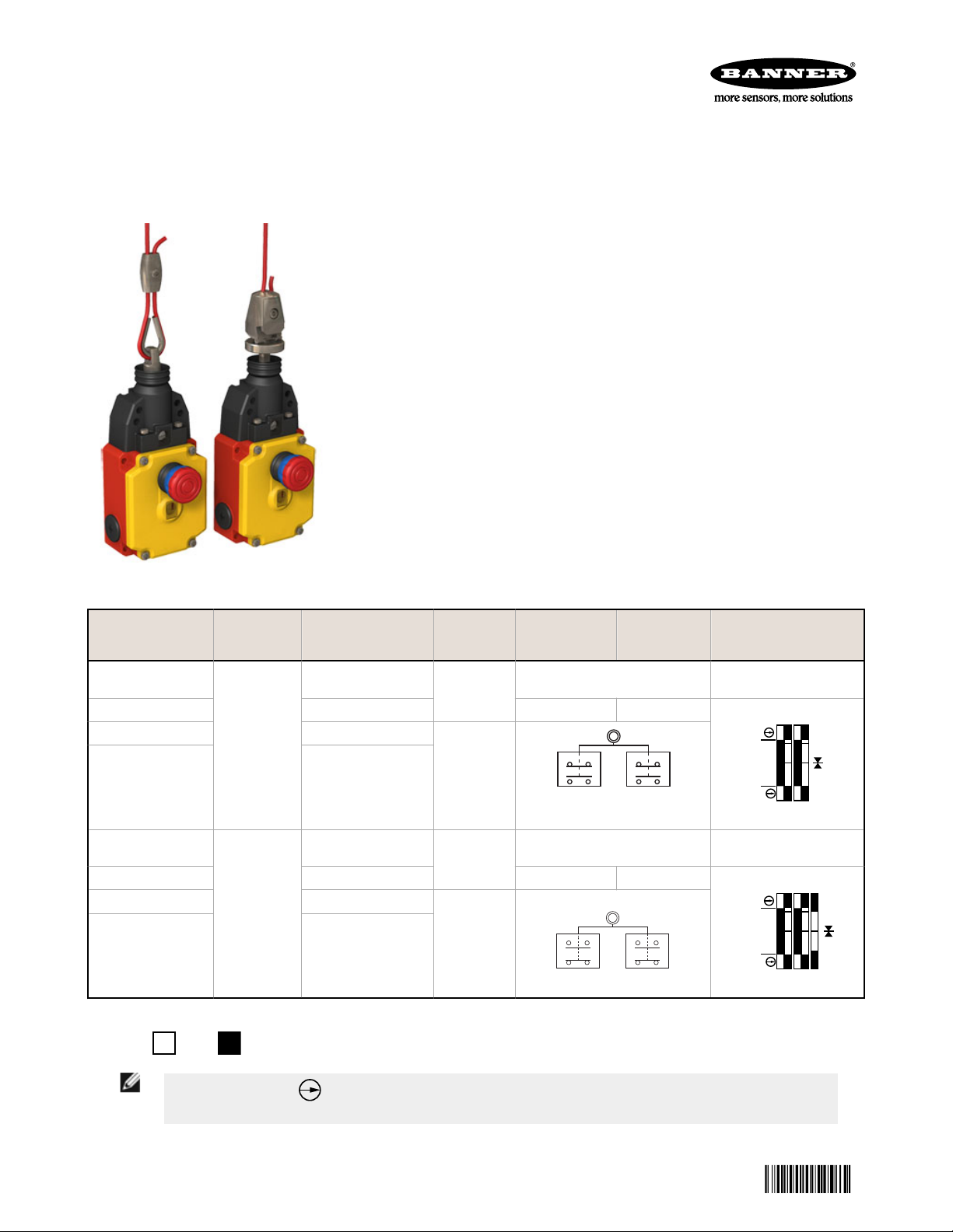
RP-RM83F Heavy-Duty Rope Pull
141245
Emergency Stop Switches
Datasheet
Rope pull switch with an emergency stop button for indoor or outdoor use
• Both safety contacts latch open when rope is pulled, broken, or if
tension is reduced; requires manual reset (IEC 60947-5-5)
• Aluminum die-cast housing, rated IP67 and NEMA 4, suitable for
demanding indoor and outdoor industrial environments
• Innovative RP-RM83F-..LT.. design provides quick, easy rope
adjustment
• Rope spans up to 75 m (245 ft), depending on model
• Both safety contacts are closed with normal rope tension, and open
when rope is pulled or if rope breaks (or if tension is reduced from
normal amount)
• Both Monitoring contacts operate opposite the safety contacts for
monitoring by another device
• Additional Aux. 24V solid-state PNP output on some models provides
remote rope tension monitoring
• Tension indicator window indicates proper rope tension for operation or
safety contacts latched open (the rope pull or the E-stop button is
actuated)
Model Max. Rope
Length
RP-RM83F-75LTE
Rope Connection Aux.
Status
Output
Built-in Turnbuckle
Yes
Run Position Cable
Pulled/
Cable Break
Cable Run Position (All
Models)
RP-RM83F-75LRE Ring S1 S2
RP-RM83F-75LT Built-in Turnbuckle
RP-RM83F-75LR Ring
RP-RM83F-38LTE
75 m (245 ft)
Built-in Turnbuckle
No
Yes
Cable Pulled / Cable Break
Position (All Models)
RP-RM83F-38LRE Ring S1 S2
RP-RM83F-38LT Built-in Turnbuckle
37.5 m (123
ft)
RP-RM83F-38LR Ring
No
Contacts: Open Closed
Switching Diagram
No PNP Aux. Output
Models
PNP Aux. Output Models
NOTE:
This symbol for a positive-opening safety contact (IEC 60947-5-1) is used in the switching
diagram to identify the point in actuator travel where the normally-closed safety contact is fully open.
P/N 141245 Rev. C 7 February 2014
Page 2

RP-RM83F Heavy-Duty Rope Pull Emergency Stop Switches
Important... Read This First
Regarding the Use of Rope Pull Switches. In the United States, the functions that Banner rope pull switches are
intended to perform are regulated by the Occupational Safety and Health Administration (OSHA). Whether or not any
particular rope pull switch installation meets all applicable OSHA requirements depends upon factors that are beyond the
control of Banner Engineering Corp. These factors include the details of how the switches are applied, installed, wired,
operated, and maintained.
Banner Engineering Corp. has attempted to provide complete application, installation, operation, and maintenance
instructions in this document. Direct any questions regarding the use or installation of rope pull switches to the factory
applications department.
Banner Engineering Corp. recommends that rope pull switches be applied according to the guidelines set forth in the
standards listed below. In addition, the user is responsible for ensuring all local, state, and national laws, rules, codes, and
regulations relating to the use of Banner rope pull switches in each application are satisfied. Extreme care is urged that all
legal requirements are met and that all installation and maintenance instructions are followed.
Applicable U.S. and International Standards (not all inclusive):
ANSI B11.0 Safety of Machinery, General Requirements, and Risk Assessment
Contact: Safety Director, AMT – The Association for Manufacturing Technology, 7901 Westpark Drive, McLean, VA
22102, Tel.: 703-893-2900
ANSI B11.19 Performance Criteria for Safeguarding
Contact: Safety Director, AMT – The Association for Manufacturing Technology, 7901 Westpark Drive, McLean, VA
22102, Tel.: 703-893-2900
ANSI NFPA 79 Electrical Standard for Industrial Machinery
Contact: National Fire Protection Association, 1 Batterymarch Park, P.O. Box 9101, Quincy, MA 02269-9101, Tel.:
800-344-3555
ANSI/RIA R15.06 Safety Requirements for Industrial Robots and Robot Systems
Contact: Robotic Industries Association, 900 Victors Way, P.O. Box 3724, Ann Arbor, MI 48106, Tel.: 734-994-6088
ISO 12100 Safety of Machinery – General Principles for Design — Risk Assessment and Risk Reduction
IEC 60204-1 Electrical Equipment of Machines Part 1: General Requirements
ISO 13850 (EN 418) Emergency Stop Devices, Functional Aspects – Principles for Design
IEC 60947-5-5 Low Voltage Switchgear – Electrical Emergency Stop Device with Mechanical Latching Function
These and other standards are available from:
NSSN National Resource for Global Standards : http://www.nssn.org/ (Tel: 212-642-4980)
IHS Standards Store : http://www.global.ihs.com/ (Tel: 303-397-7956, 800-854-7179)
Document Center : http://www.document-center.com/home.cfm (Tel: 650-591-7600)
EC Declaration of Conformity (DOC)
Banner Engineering Corp. herewith declares that the RP-RM83F Heavy-Duty Rope Pull Emergency Stop Switches are
in conformity with the provisions of the Machinery Directive and all essential health and safety requirements have been
met.
Representative in EU: Peter Mertens, Managing Director Banner Engineering Europe. Address: Park Lane, Culliganlaan 2F,
1831 Diegem, Belgium.
Overview
Models RP-RM83F-.. are rope pull emergency stop switches in compact, heavy-duty die-cast aluminum housings, for indoor
or outdoor use. When used with steel wire rope, they can provide emergency stop actuation along conveyors and similar
machinery. Red PVC-covered 2, 3, 4, or 5 mm diameter wire rope is recommended, depending on model (force) and rope
distance.
The switches have redundant contacts; terminals 11/12 are positive opening when there is a cable-pull or cable-brake
situation. When used separately, these contacts provide inputs to a dual-channel safety module. Terminals 11/12 can also
be used individually to provide single-channel switching or as a single-channel input to a safety module. Terminals 23/24
are for monitoring purposes only (closed in a cable-break/cable-pull situation).
When the rope is properly tensioned (228 or 133N, depending on model), the red arrows are centered under the hash
mark on the tension indicator window, the contacts at terminals 11/12 are closed, and the contacts at terminals 23/24 are
open. All models feature a “latching” operation. When the rope is pulled, the switch contacts 11/12 open and remain open
until the built-in E-stop/reset button is manually reset.
These rope pull emergency stop switches are not generally considered safeguarding devices, in that they do not prevent or
reduce exposure of individuals to a hazard. They provide the same function as other types of emergency stop switches.
2 www.bannerengineering.com - tel: 763-544-3164 P/N 141245 Rev. C
Page 3
Green
Yellow
Yellow
RP-RM83F Heavy-Duty Rope Pull Emergency Stop Switches
WARNING: Not a Safeguarding Device
An Emergency Stop Device is not considered a safeguarding device because it requires an
overt action by an individual to stop machine motion or hazards.
A safeguarding device limits or eliminates an individual's exposure to a hazard without action by the
individual or others. Because an individual must actuate the device for it to function, these devices do
not fit the definition of a safeguarding device and cannot be substituted for required safeguarding. Refer
to the relevant standards to determine those requirements.
WARNING: Emergency Stop Functions
Do not mute or bypass any Emergency Stop device. ANSI B11.19, ANSI NFPA79 and IEC/EN
60204-1 require that the Emergency Stop function remain active at all times.
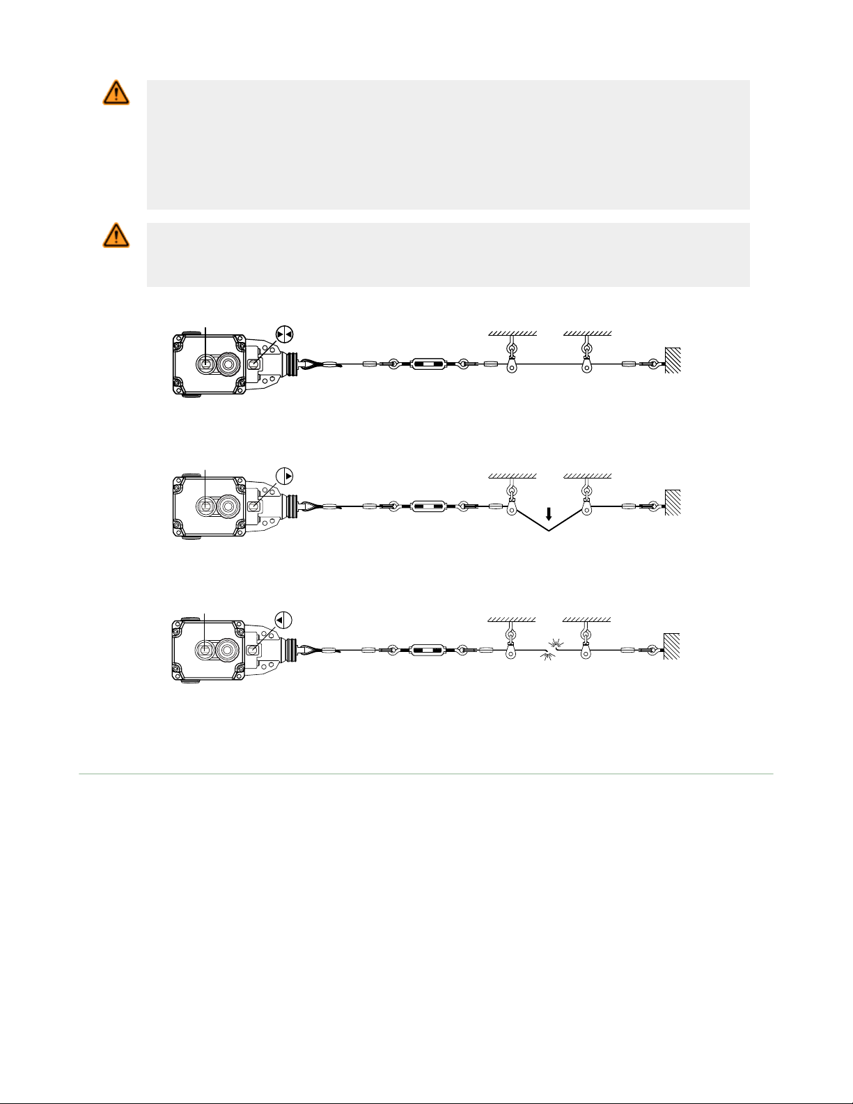
Figure 1. Run Condition (Proper Rope Tension) - Contacts 11/12 Closed
Figure 2. Rope Pulled Condition - Contacts 11/12 Open
Figure 3. Rope Break Condition - Contacts 11/12 Open
Mechanical Installation
• The rope should be easily accessible and visible along its entire length. Markers or flags may be fixed on the rope
to increase its visibility
• Switch body, anchor mounts and wire rope supports (pulleys or eye bolts) must be rigid and secure
• Although pulleys are preferred, a combination of pulleys and/or eye bolts are required to support the wire rope
along its length. When pulled, the wire rope, should move freely through the pulleys or eye bolts to actuate the
switch
• Use only pulleys (not eye bolts) when routing the rope around a corner or whenever direction changes, even
slightly
• Never run rope through conduit or other tubing
• Never attach weights to the rope
• Temperature affects rope tension. The rope expands (lengthens) when temperature increases, and contracts
(shrinks) when temperature decreases. Significant temperature variations require frequent checks of the tension
adjustment
• Do not exceed the maximum specified total rope length. Banner offers models for other spans; contact Banner
Engineering or visit www.bannerengineering.com for model selection
P/N 141245 Rev. C www.bannerengineering.com - tel: 763-544-3164 3
Page 4
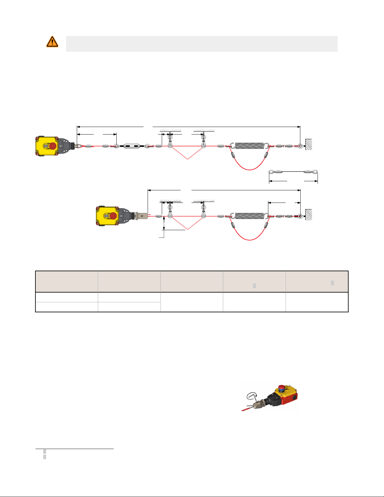
340 mm
L3
Spring breakage
protector cable
L1
L1
L3
L4 L2
L4
400 mm (16") max.
for actuation of switch
Note:
Force to actuate must
not exceed 200 N (45lbf)
L2
RP-RM83F Heavy-Duty Rope Pull Emergency Stop Switches
WARNING: Failure to use pulleys or eye bolts to support the wire rope can result in damage to the
switch and may create a dangerous situation that could lead to serious injury or death.
Installation Procedure
1. Mount the switch securely on a solid stationary surface.
2. Fasten an eye bolt at the opposite end of the rope span from the switch. Verify that the anchor for the eye bolt is
solid and stationary to withstand the constant tension and possible pull of the rope.
3. Assemble the rope as shown. Keep the rope’s PVC cover intact along its complete length.
4. Use pulleys (recommended) or eye bolts at each support point. Always use a pulley when routing the rope around
a corner, regardless of the angle.
Figure 4. Assembly of Rope and Hardware
Switch Model
75 m 75 m (245 ft)
38 m 37.5 m (123 ft)
Max. Total Length L1
Max. Distance
Between Pulleys L2
3-5 m (10-15 ft) 150 mm (6 inches) 150 mm (6 ft)
Max. Distance to
Spring/Turnbuckle L3
1
Min. Distance Fitting
to Pulley L4
2
All hardware is supplied by the user. See Dimensions for switch mounting hole mounting pattern and size.
Installing Models RP-RM83F-..75 and RP-LS42F-xxLF (with Integral Turnbuckle)
These models have their own integral turnbuckle and clamp to tension the rope and to hold it in place. This innovative
design provides for quick and easy rope fixing and tensioning. These models require no external turnbuckle or any
additional clamp at the switch end of the rope.
To install the rope at the switch end:
1. Strip away several inches of the cable covering.
2. Loosen the set screw on the switch fitting using a 4
mm hex wrench.
3. Insert the cable into the center hole, and pull the
cut end out from the side hole.
4. When the tension is correct, tighten the set screw to
hold the rope firmly in place.
Figure 5. Tightening the rope into the internal turnbuckle (models
RP-RM83F-..LT and -..LTE)
1
Closer, if possible
2
Distance must allow necessary clearance to all mounting hardware.
4 www.bannerengineering.com - tel: 763-544-3164 P/N 141245 Rev. C
Page 5

11 12
23 24
11 12
23 24
–
+
1
2
3
1
2
3
Load
10-30 VDC
PNP
Warning Signal
Connections
11 12
23 24
11 12
23 24
–
+
1
2
3
1
2
3
Load
10-30 VDC
Channel A Channel B
RP-RM83F Heavy-Duty Rope Pull Emergency Stop Switches
Tensioning the Rope
After the rope span components are installed, apply tension to the rope until the arrows in the tensioning indicator are
centered on the line in the tension indicator window. This indicates sufficient rope tension. (Contacts 11/12 will close.)
1. For models RP-RM83F-..LT and RP-RM83F-..LTE: Turn the external turnbuckle until the arrows are centered. For
models RP-RM83F-..LR and RP-RM83F-..LRE: Turn the shaft of the switch using a 17 mm wrench as shown, until
the arrows are centered.
2. Pull hard on the rope and reset the latch several times. If the arrows in the tensioning indicator window do not
return to the correct position (centered on the line in the window), further tighten or loosen the rope tension as
needed, then reset, until proper tension is shown.
3. Check the tension adjustment periodically to ensure proper operation.
Figure 6. Tension Indicator
Window: too little tension shown
Figure 7. Tension Indicator
Window: proper tension shown
Figure 8. Adjusting rope tension (models RP-RM83F-..LT
and-..LTE)
Electrical Installation
Accessing the Wiring Chamber
Access the wiring chamber by loosening the four corner screws to remove the front cover. Select the best wiring entrance
and thread in the ½" x 14 NPSM conduit adapter (supplied), or the optional M20 x 1.5 cable gland (see Accessories). Wire
the two switch contacts in series or independently.
Figure 9. Single-Channel Connection
WARNING: Shock Hazard and Hazardous Energy
Always disconnect power from the safety system (for example, device, module, interfacing,
etc.) and the machine being controlled before making any connections or replacing any
component.
Electrical installation and wiring must be made by Qualified Personnel and must comply with the
relevant electrical standards and wiring codes, such as the NEC (National Electrical Code), ANSI
NFPA79, or IEC 60204-1, and all applicable local standards and codes.
Lockout/tagout procedures may be required. Refer to OSHA 29CFR1910.147, ANSI Z244-1, ISO
14118, or the appropriate standard for controlling hazardous energy.
P/N 141245 Rev. C www.bannerengineering.com - tel: 763-544-3164 5
Figure 10. Dual-Channel Connection
Page 6

–
+
1
2
3
0 V dc
+24 V
1
2
3
Load
RP-RM83F Heavy-Duty Rope Pull Emergency Stop Switches
Wiring
These switch models have redundant pairs of safety contacts, so they may be wired for either single-channel or dualchannel output to a safety module or E-stop circuit. Monitor contacts may be wired as desired to an external alarm device.
CAUTION: Proper Wiring. Maximum tightening torque of contact screws is specified at 0.8 Nm; do not
over-tighten. Before closing the front cover, verify no wires are trapped. Do not operate the rope pull
without properly closing the cover.
Single-Channel Output: Wire contacts 11/12 together in series to the input of a safety module or E-stop circuit.
Dual-Channel Output: Wire contacts 11/12 independently to the two safety module inputs.
Warning Signal. Switch models RP-RM83F-...E provide a
24 V dc solid-state “warning signal” output, which signals
when the rope tension is either too high or too low, before
the safety contacts open and the switch latches OFF. This
solid-state switch is located inside the wiring chamber next
to the safety output contacts.
Figure 11. Warning Signal Electrical Connections
Manual/Latch Reset
E-Stop and Latch Reset. Following the rope pulling/
breaking or the E-stop button being pressed, the latch must
be manually reset. The E-stop can be reset only when
proper tension is indicated. Pull the red E-stop button until
the switch Status indicator changes from Yellow to Green
and the latch makes an audible “click,” indicating that the
latch has been reset.
NOTE: Proper rope tension must be
displayed before the latch can be reset.
Figure 12. Resetting the Latch
Maintenance/Checkout
At switch installation or replacement and at machine set up, a Designated Person3 must test each switch for proper
machine shutdown response and check the switch(es) and installation for proper operation, physical damage, mounting
(looseness), and excessive environmental contamination. This must also take place on a periodic schedule determined by
the user, based on the severity of the operating environment and the frequency of switch actuations. Adjust, repair, or
replace components as needed. If inspection reveals contamination on the switch, thoroughly clean the switch and
eliminate the cause of the contamination. Replace the switch and/or appropriate components when any parts or
assemblies are damaged, broken, deformed, or badly worn; or if the electrical/mechanical specifications (for the
environment and operating conditions) have been exceeded. Always test the control system for proper functioning under
machine control conditions after performing maintenance, replacing the switch, or replacing any component of the switch.
Additional items that should be included in the checkout and/or regularly scheduled maintenance of a rope pull system:
3
A Designated Person is identified in writing by the employer as being appropriately trained to perform a specified checkout procedure.
6 www.bannerengineering.com - tel: 763-544-3164 P/N 141245 Rev. C
Page 7

RP-RM83F Heavy-Duty Rope Pull Emergency Stop Switches
• Check for proper rope tension and adjust as needed
• Verify free operation (no binding) of the rope and proper tripping when the rope is pulled
• Periodically lubricate the pulleys and other moving parts associated with the rope
• Repair any loose or damaged hardware, worn/frayed rope (cable), missing red rope sheathing or flags/markers (if
used)
• Remove or clean off any contamination and eliminate its cause
Repairs
Contact Banner Engineering for troubleshooting of this device. Do not attempt any repairs to this Banner device; it
contains no field-replaceable components. If the device or a device component is determined to be defective by a
Banner Applications Engineer, they will advise you of Banner's RMA (Return Merchandise Authorization) procedure.
Important: If instructed to return the device, pack it with care. Damage that occurs in return shipping
is not covered by warranty.
Specifications
Contact Rating
10 A at 24 V ac
10 A at 110 V ac
6 A at 230 V ac
6 A at 24 V dc
2.5 kV max. transient tolerance
NEMA A300 P300
Monitoring Solid-State Output Rating
Rated operational voltage: Ue = 10 to 30 V dc
Rated operational current: = 50 mA
Utilization category: DC13
Protected against reverse polarity and short circuit
European Rating
Utilization categories: AC15 and DC13
Ui = 500 V ac; Ith = 10 A
Rated surge capacity: 2.5 kV
40-60 Hz
Ue (V) Ie/AC-15 (A) Ie/DC-13 (A)
120 6 0.55
240 3 0.27
Contact Material
Silver-nickel allow
Maximum Switching Speed
20 operations per minute
Recommended Rope Size
Accommodates rope sizes 2 to 5 mm diameter steel rope (see
Accessories); select rope diameter based on switch model and rope
length
75 m models: recommended 2 to 5 mm diameters
38 m models: recommended 2 to 5 mm diameters
Maximum Rope Pull Length
75 m (245 ft) or 37.5 m (123 ft), depending on model
Short Circuit Protection
10 amp Slow Blow, 15 amp Fast Blow. Recommended external
fusing or overload protection.
Mechanical Life
100,000 operations
Wire Connections
Screw terminals with pressure plates accept the following wire
sizes:
Stranded and solid: 20 AWG (0.5 mm2) to 16 AWG (1.5 mm2) for
one wire
Stranded: 20 AWG (0.5 mm2) to 18 AWG (1.0 mm2) for two wires
Cable Entry
M20 x 1.5 threaded entrance. Adapter supplied to convert M20 x
1.5 to ½"-14 NPT threaded entrance
Construction
Die-cast aluminum housing; zinc die-cast actuator
Environmental Rating
NEMA 4, IEC IP67, per IEC/EN 60529
Operating Conditions
Temperature: –30 °C to 80 °C (–34 °F to 176 °F)
Weight
RP-RM83F-..LT and -..LTE: 1Kg (2.1 lbs.)
RP-RM83F-..LR and -..LRE: 0.77 Kg (1.6 lbs.)
Product Performance Standards
DIN EN 60947-1, DIN EN 60947-5-1, DIN EN 60947-5-5, IEC
60947-1, IEC 60947-5-1, IEC 60947-5-5, ISO 13850
Certifications
P/N 141245 Rev. C www.bannerengineering.com - tel: 763-544-3164 7
Page 8

8.5 mm
(0.33")
88 mm
(3.5")
53 mm
(2.1")
20.5 mm
(0.80")
20.5 mm
(0.80")
30.5 mm
(1.20")
20.5 mm
(0.80")
M20 x 1.5
40 mm
(1.6")
max. 197 mm / min. 185 mm
(max. 7.8" / min. 7.3")
127 mm
(5.0")
10 mm
(0.4")
85.5 mm
(3.37")
8 mm
(0.3")
90 mm
(3.5")
72 mm
(2.8")
78 mm
(3.1")
48 mm
(1.9")
Ø 6.5 mm
x 4
(0.26")
Ø 5.4 mm
x 4
(0.21")
RP-RM83F Heavy-Duty Rope Pull Emergency Stop Switches
Dimensions
Figure 13. RP-RM83F-..LR..
8 www.bannerengineering.com - tel: 763-544-3164 P/N 141245 Rev. C
Page 9

88 mm
(3.5")
53 mm
(2.1")
20.5 mm
(0.80")
26 mm
(1.0")
30.5 mm
(1.20")
m20 x 1.5
40 mm
(1.6")
max. 282 mm / min. 237 mm
(max. 11.1" / min. 9.3")
127 mm
(5.0")
10 mm
(0.4")
85.5 mm
(3.37")
8 mm
(0.3")
90 mm
(3.5")
72 mm
(2.8")
78 mm
(3.1")
48 mm
(1.9")
Ø 6.5 mm
x 4
(0.26")
Ø 5.4 mm
x 4
(0.21")
Ø 36 mm
(1.4")
20.5 mm
(0.80")
SW17
Spring breakage
protector cable
Thimble
Clamp Turnbuckle Spring Eye BoltPulley
RP-RM83F Heavy-Duty Rope Pull Emergency Stop Switches
Accessories
Figure 14. RP-RM83F-..LT..
Figure 15. Wire Rope Assembly Components
P/N 141245 Rev. C www.bannerengineering.com - tel: 763-544-3164 9
Page 10

RP-RM83F Heavy-Duty Rope Pull Emergency Stop Switches
Model Length Description Wire Rope
RPA-C1-10 10 m (33 ft)
RPA-C1-20 20 m (66 ft)
2 mm steel wire rope with 0.5 mm red PVC jacket
(unterminated)
RPA-C1-100 100 m (330 ft)
Model Length Description Wire Rope
RPA-C2-10 10 m (33 ft)
RPA-C2-20 20 m (66 ft)
RPA-C2-50 50 m (264 ft)
3 mm steel wire rope with 0.5 mm red PVC jacket
(unterminated)
RPA-C2-80 80 m (264 ft)
Model Length Description Wire Rope
RPA-C3-10 10 m (33 ft)
RPA-C3-100 100 m (330 ft)
4 mm steel wire rope with 0.5 mm red PVC jacket
(unterminated)
Model Quantity Description Thimble
RPA-T1-4 4 Thimble for 2 mm wire rope
RPA-T2-4 4 Thimble for 3 mm wire rope
RPA-T3-4 4 Thimble for 4 mm wire rope
Model Quantity Description Clamp
RPA-CC1-4 4 Clamp for 2 mm wire rope
RPA-CC2-4 4 Clamp for 3 mm wire rope
RPA-CC3-4 4 Clamp for 4 mm wire rope
Model Quantity Description Turnbuckle
RPA-TA1-1 1 #4 Turnbuckle
Model Quantity Description Eye Bolt
RPA-EB1-1 1 ¼"-20 Eye bolt (3" bolt shaft)
Model Quantity Description Pulley
RPA-P1-1 1 Hanging pulley for in-line use
RPA-DP1-1 1 Right-angle mount deflection pulley for corner turns (90 to
180 degrees)
10 www.bannerengineering.com - tel: 763-544-3164 P/N 141245 Rev. C
Page 11

M20 x 1.5
24.0 mm
(0.94")
35.5 mm
(1.40")
23.0 mm
(0.91")
M20 x 1.5
24.0 mm
(0.94")
1/2"-14 NPT
Internal Thread
O-ring
RP-RM83F Heavy-Duty Rope Pull Emergency Stop Switches
Model Quantity Description Tensioning Spring Used With
RPA-S3-1 1 Tensioning spring #3 RP-LM40D-6
RP-LM40D-6L
RP-RM83F-..75..
RPA-S5-1 1 Tensioning spring #5 RP-RM83F-..38..
Model Quantity Description Tensioning Spring Used With
RPA-S4-1 1 Tensioning spring #4 with built-in eye
bolt, cable thimble, clamping, tensioning,
and overload protection.
RPA-S6-1 1 Tensioning spring #6 with built-in eye
RP-LM40D-6
RP-LM40D-6L
RP-RM83F-..75..
RP-RM83F-..38..
bolt, cable thimble, clamping, tensioning,
and overload protection.
Model Size
For Cable
Diameter
Dimensions Used With
SI-LM40 Safety Interlock
Switches
SI-QM100 Safety Interlock
SI-QM-CGM20 M20 × 1.5 Metal
5.0 to 12.0 mm
(0.20 to 0.47 inches)
Switches
RP-RM83 Rope Pull Switches
RP-LM40 Rope Pull Switches
RP-QM72/QMT72 Rope Pull
Switches
RP-QM90 Rope Pull Switches
Model Size Thread Conversion Dimensions Used With
SI-LM40 Safety Interlock
Switches
SI-QM100 Safety Interlock
SI-QM-M20
½ in-14 NPT
Metal
M20 × 1.5 to ½
in-14 NPT
Switches
RP-RM83 Rope Pull Switches
RP-LM40 Rope Pull Switches
RP-QM72/QMT72 Rope Pull
Switches
RP-QM90 Rope Pull Switches
Banner Engineering Corp Limited Warranty
Banner Engineering Corp. warrants its products to be free from defects in material and workmanship for one year following
the date of shipment. Banner Engineering Corp. will repair or replace, free of charge, any product of its manufacture
which, at the time it is returned to the factory, is found to have been defective during the warranty period. This warranty
does not cover damage or liability for misuse, abuse, or the improper application or installation of the Banner product.
THIS LIMITED WARRANTY IS EXCLUSIVE AND IN LIEU OF ALL OTHER WARRANTIES WHETHER EXPRESS OR
IMPLIED (INCLUDING, WITHOUT LIMITATION, ANY WARRANTY OF MERCHANTABILITY OR FITNESS FOR A
PARTICULAR PURPOSE), AND WHETHER ARISING UNDER COURSE OF PERFORMANCE, COURSE OF DEALING OR
TRADE USAGE.
This Warranty is exclusive and limited to repair or, at the discretion of Banner Engineering Corp., replacement. IN NO
EVENT SHALL BANNER ENGINEERING CORP. BE LIABLE TO BUYER OR ANY OTHER PERSON OR ENTITY FOR
ANY EXTRA COSTS, EXPENSES, LOSSES, LOSS OF PROFITS, OR ANY INCIDENTAL, CONSEQUENTIAL OR
SPECIAL DAMAGES RESULTING FROM ANY PRODUCT DEFECT OR FROM THE USE OR INABILITY TO USE THE
PRODUCT, WHETHER ARISING IN CONTRACT OR WARRANTY, STATUTE, TORT, STRICT LIABILITY,
NEGLIGENCE, OR OTHERWISE.
Banner Engineering Corp. reserves the right to change, modify or improve the design of the product without assuming any
obligations or liabilities relating to any product previously manufactured by Banner Engineering Corp.
www.bannerengineering.com - tel: 763-544-3164
 Loading...