

Page 1
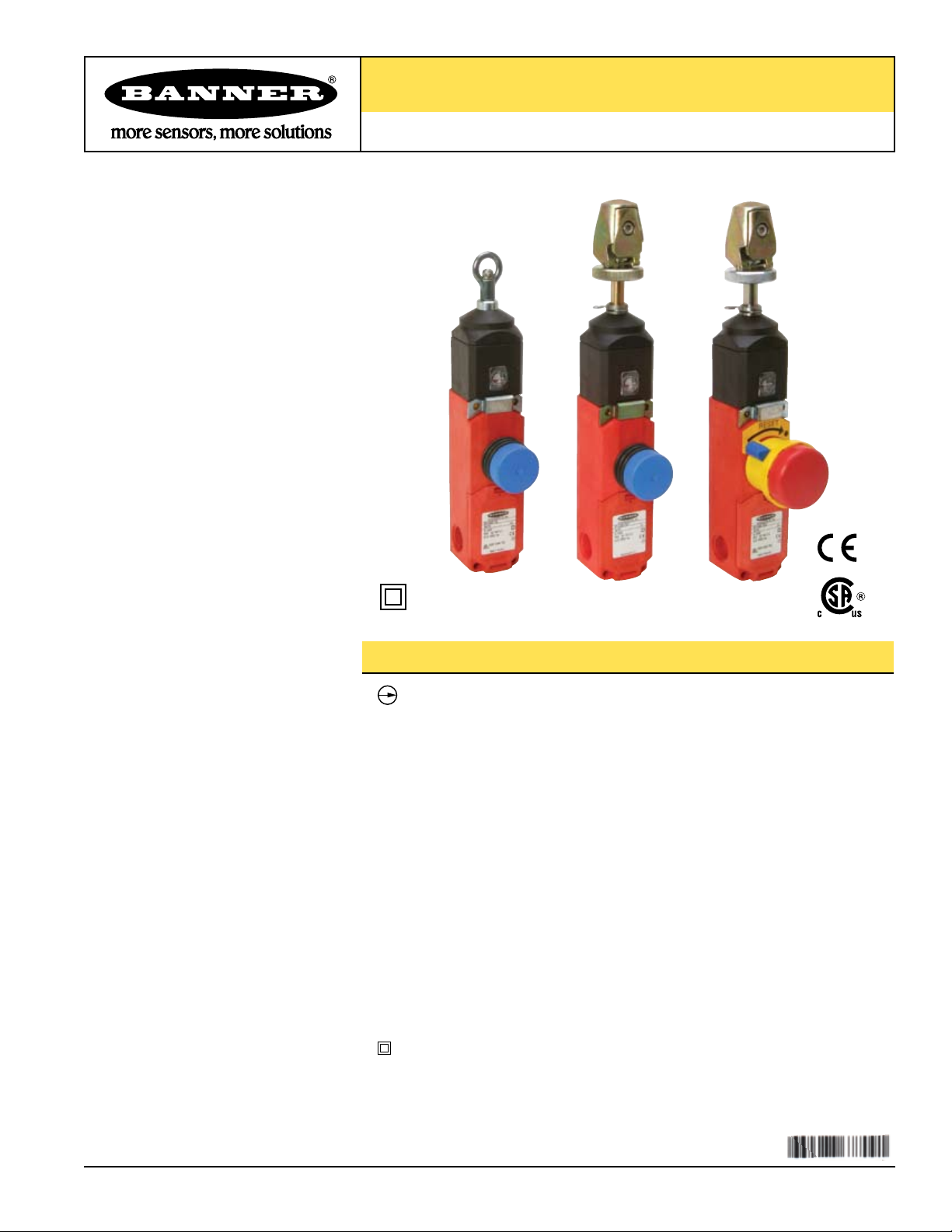
Rope Pull Emergency Stop Switches
RP-LS42F-75L.. Series 42 mm Latching Switches with Rope Actuators
Features
•
Positive-opening safety contacts (IEC 60947-5-1), not dependent
upon springs
• Contacts latch open when rope is pulled; requires manual reset
• Heavy-duty thermoplastic housing, rated IP67 and NEMA 4, suitable
for demanding industrial environments
• Innovative design provides quick, easy rope fixing and tensioning on models
RP-LS42F-75LE and RP-LS42F-75LF
• Rope spans up to 75 m (245')
• Both safety contacts are closed with normal rope tension, and open when rope is
pulled or if rope breaks (or if tension is reduced from normal amount)
• Extra contacts for monitoring or to provide dual-channel input to a safety module
• Indicator mark on switch shows when rope has proper tension for operation
• Long life, switch rated at 1 million mechanical operations, minimum
• Three available models: one with E-stop button, all with latching outputs
Insulated device (IEC 60947-5-1) on all models with plastic housings
•
Printed in USA 07/06 P/N 67709 rev. A
Page 2
Rope Pull Emergency Stop Switches –
RP-LS42F-75L.. Series
Important Information
Regarding the Use of Rope Pull Emergency Stop Switches
In the United States, the functions that Banner rope pull emergency stop switches are intended to perform are regulated by the Occupational
Safety and Health Administration (OSHA). Whether or not any particular rope pull switch installation meets all applicable OSHA requirements
depends upon factors that are beyond the control of Banner Engineering Corp. These factors include the details of how the switches are applied,
installed, wired, operated, and maintained.
Banner Engineering Corp. has attempted to provide complete application, installation, operation, and maintenance instructions. This information is
found in the instruction manual packaged with each rope pull switch. Direct any questions regarding the use or installation of rope pull switches to
the factory applications department at the telephone numbers or address shown below.
Banner Engineering Corp. recommends that rope pull emergency stop switches be applied according to the guidelines set forth in standards listed
below. In addition, the user of Banner rope pull switches has the responsibility to ensure that all local, state, and national laws, rules, codes,
and regulations relating to the use of Banner rope pull switches in any particular application are satisfied. Extreme care is urged that all legal
requirements have been met and that all installations and maintenance instructions are followed.
Application Assistance
Toll Free: 1-888-3-SENSOR (1-888-373-6767)
Email: sensors@bannerengineering.com
Address: 9714 Tenth Avenue North
Minneapolis, MN 55441
U. S. Standards Applicable to Use of Emergency Stop Safety Modules
ANSI B11 Standards for Machine Tools “Safety Requirements for the Construction, Care and Use”
Available from: Safety Director
AMT—The Association for Manufacturing Technology
7901 Westpark Drive
McLean, VA 22102
Tel.: 703-893-2900
NFPA79 “Electrical Standard for Industrial Machinery (1997)”
Available from: National Fire Protection Association
1 Batterymarch Park, P.O. Box 9101
Quincy, MA 02269-9101
Tel.: 800-344-3555
ANSI/RIA R15.06 “Safety Requirements for Industrial Robots and Robot Systems”
Available from: Robotic Industries Association
900 Victors Way, P.O. Box 3724
Ann Arbor, MI 48106
Tel.: 734-994-6088
European Standards Applicable to Use of Emergency Stop Safety Modules
ISO/TR12100-1&-2 “Safety of Machinery—Basic Concepts, General Principles for Design
(EN 292-1 & -2) Part 1: Basic Terminology, Methodology”; Part 2: Technical Principles and Specifications
ISO13849-1 (EN 954-1) “Safety of Machines—Safety Related Parts of Control Systems”
IEC/EN 60204-1 “Electrical Equipment of Machines: Part 1: General Requirements”
Also, request a type “C” standard for your specific machinery.
ISO13850 (EN 418) “Safety of Machinery—Emergency Stop Equipment Functional Aspects, Principles for Design”
IEC 60947-5-5 “Electrical Emergency Stop Devices with Mechanical Latching Function”
Available from: Global Engineering Documents
15 Inverness Way East
Englewood, CO 80112-5704
Tel.: 800-854-7179
2 P/N 67709 rev. A
Banner Engineering Corp. • Minneapolis, MN U.S.A.
www.bannerengineering.com • Tel: 763.544.3164
Page 3
Rope Pull Emergency Stop Switches –
21 22
13 14
41 42
33 34
21 22
13 14
41 42
33 34
21 22
13 14
41 42
33 34
13-14
21-22
Break (180N)
Tension
Set Point
240N
Latch
Pull (300N)
-5 (0.20)
+5 (0.20)
-3.8 (0.15)
-3 (0.12)
+3 (0.12)
mm (in)
+3.8 (0.15)
33-34
41-42
Latch
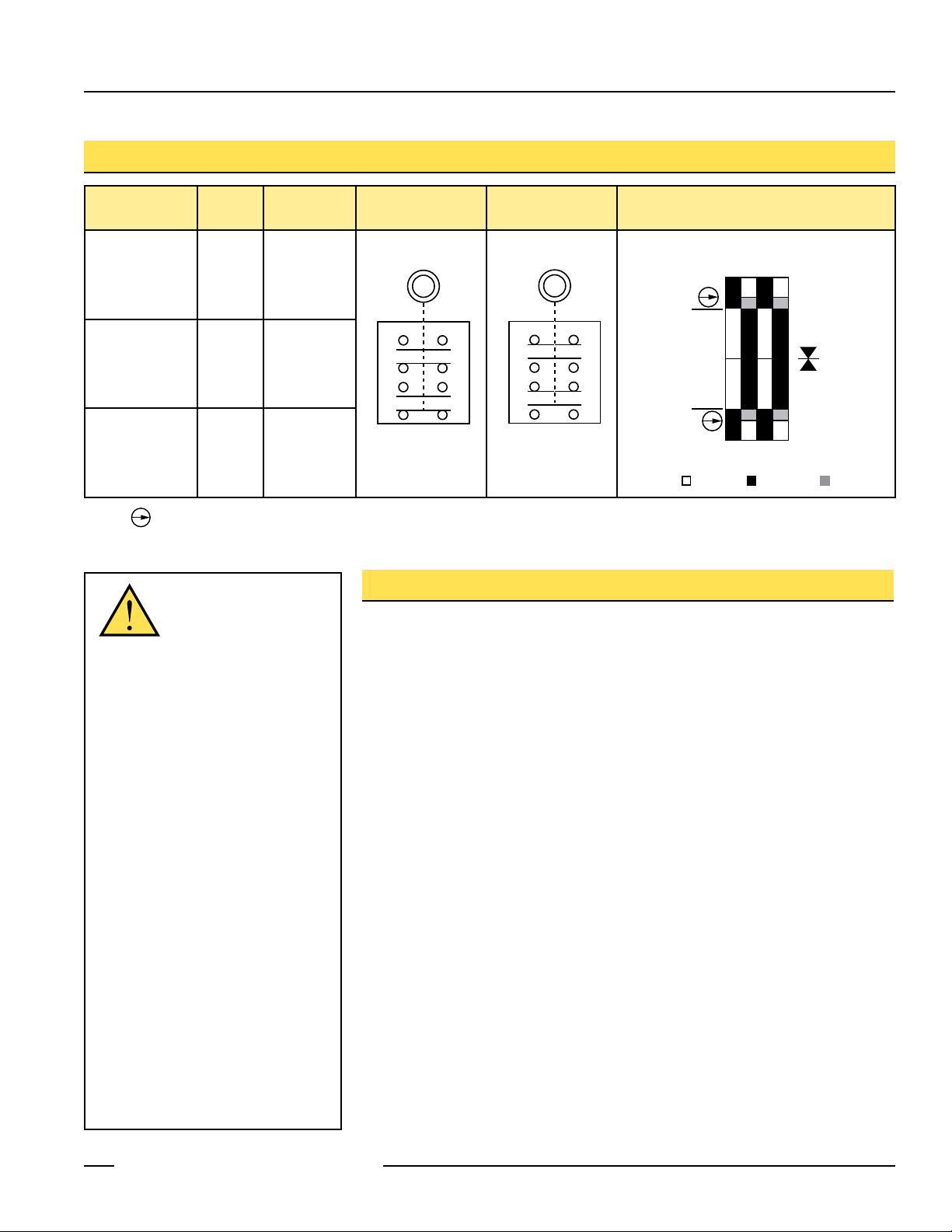
Models
RP-LS42F-75L.. Series
†
Model
RP-LS42F-75L No No
RP-LS42F-75LE Yes Yes
RP-LS42F-75LF No Ye s
NOTE: This symbol for a positive-opening safety contact (IEC 60947-5-1) is used in the switching diagram to identify the point in actuator travel where
the normally-closed safety contact is fully open.
E-Stop
Built-in
Turnbuckle
WARNING ...
Run
Position
Cable Pulled/
Cable Break
Contacts:
Overview
Switching
Diagram
Open Closed Transition
Not a Safeguarding
Device
An Emergency Stop Device, including,
but not limited to buttons, rope pulls and
cable pulls, is not generally considered
a safeguard; and does not alone fulfill
U.S. or International requirements for
safeguarding hazards associated with
machinery.
The definition of safeguarding is the
"protective measure using safeguards [guards
or protective devices] to protect persons from
the hazards which cannot reasonably be
eliminated..." (ISO12100-1, 3.29 and 3.30).
A safeguard limits or eliminates an individual's
exposure to a hazard (examples include
interlocking devices, safety mats, safety light
screens). An emergency stop is considered
to be a complementary protective measure,
which is neither an inherently safe design
measure, nor safeguarding, but may
be required as part of the safety related
control system and risk reduction strategy
(ISO12100-2, 4.5.1 and 4.5.2).
The user must refer to the relevant
standard(s) to determine the safeguarding
requirements for their particular situation.
Banner Engineering Corp. • Minneapolis, MN U.S.A.
P/N 67709 rev. A 3
www.bannerengineering.com • Tel: 763.544.3164
Models RP-LS42F-75L.. are rope pull emergency stop switches in compact, limit switchstyle housings made of high-impact thermoplast. When used with steel wire rope, they
can provide emergency stop actuation along conveyors and similar machinery. Red
PVC-covered 3 mm diameter wire rope is recommended (see page 10).
The switches have redundant contacts; terminals 21/22 and 41/42 are positive opening
when there is a cable-pull or cable-brake situation. When used separately, these contacts
provide inputs to a dual-channel safety module (see Figure 6). Terminals 21/22 and
41/42 can also be used individually to provide single-channel switching or as a singlechannel input to a safety module. Terminals 13/14 and 33/34 are for monitoring purposes
only (closed in a cable-brake/-pull situation).
When the rope is properly tensioned (240N), the red arrows are centered on the hash
mark on the tension indicator window, the contacts at terminals 21/22 and 41/42 are
closed, and the contacts at terminals 13/14 and 33/34 are opened (see Figures 1, 2
and 4).
These rope pull emergency stop switches are not generally considered safeguarding
devices, in that they do not prevent or reduce exposure of individuals to a hazard. They
provide the same function as other types of emergency stop switches.
All models feature “latching” operation. When the rope is pulled, the switch contacts
21/22 and 41/42 open and remain open until the built-in reset button is manually reset
(see Figure 1).
Page 4
Rope Pull Emergency Stop Switches –
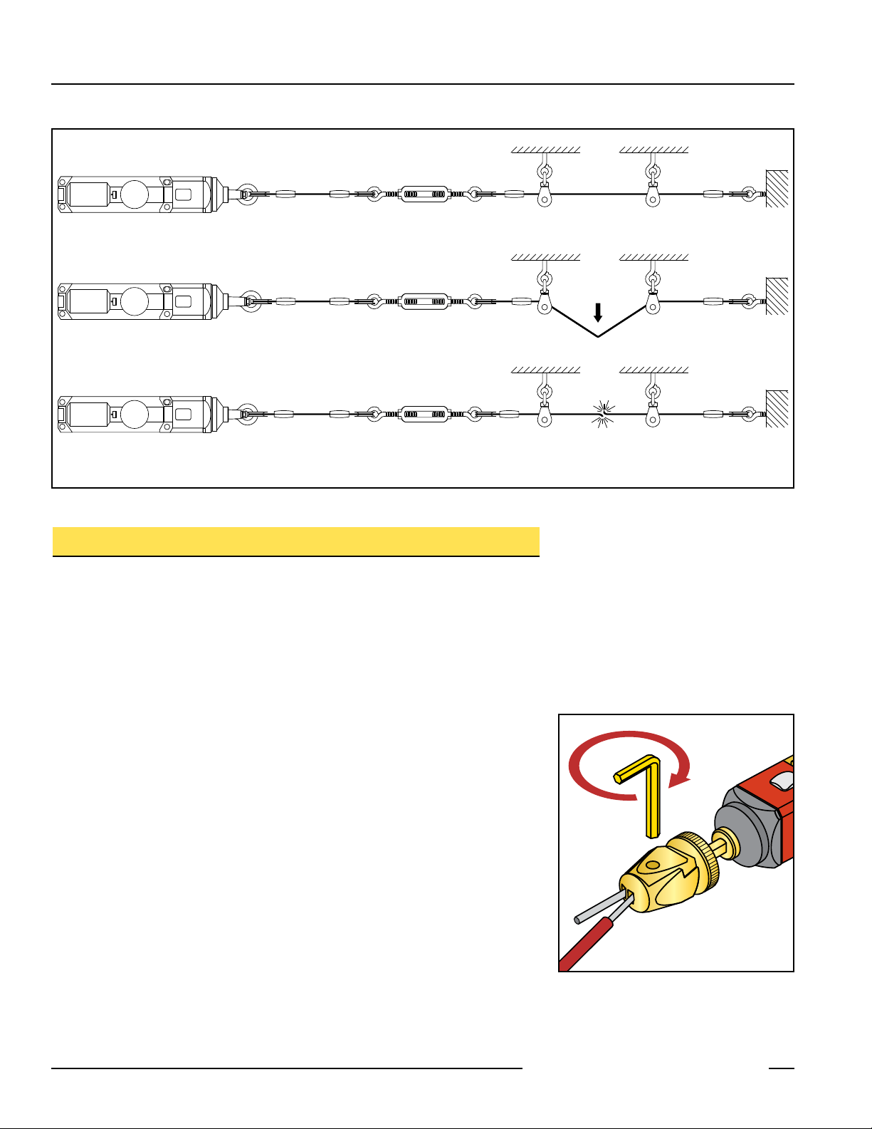
Run Position: Proper Rope Tension
Rope Pulled: Contacts S21/22 and 41/42 Open
Rope Break or Slack: Contacts S21/22 and 41/42 Open
RP-LS42F-75L.. Series
Figure 1. Run, rope pulled, and rope break switch positions
Mechanical Installation
Installation Guidelines
• The wire rope should be easily accessible and visible along its entire length. Markers
or flags may be fixed on the rope to increase its visibility.
• Mounting points, including support points, must be rigid.
• The rope should be free of friction at all supports. Pulleys are recommended.
• Use only pulleys (not eye bolts) when routing the rope around a corner, or whenever
direction is changed, even slightly.
• Never run rope through conduit or other tubing.
• Never attach weights to the rope.
• Temperature affects rope tension. The rope expands (lengthens) when temperature
increases, and contracts (shrinks) when temperature decreases. Significant
temperature variations require frequent checks of the tension adjustment.
• Do not exceed the maximum total rope length, as specified in Figure 3. Banner offers
models for greater spans; contact the factory or visit www.bannerengineering.com for
model selection.
Installation Procedure
1. Mount the switch securely on a solid, stationary surface.
2. Fasten an eye bolt at the opposite end of the rope span, up to 75 m (245') from the
switch. The anchor for the eye bolt also must be solid and stationary, to withstand the
constant tension and possible pull of the rope.
3. Assemble the rope, as shown in Figure 3. Keep the rope’s PVC cover intact along its
complete length.
4. Use pulleys (recommended) or eye bolts at each support point. A pulley must be used
when routing the rope around a corner, regardless of the angle.
4 P/N 67709 rev. A
Figure 2. Tightening the rope into the internal
turnbuckle (models RP-LS42F-75LE
and RP-LS42F-75LF)
Banner Engineering Corp. • Minneapolis, MN U.S.A.
www.bannerengineering.com • Tel: 763.544.3164
Page 5

Rope Pull Emergency Stop Switches –
340 mm
L3
Spring breakage
protector cable
L1
L1
L3
L4 L2
L4L4
400 mm (16") max.
for actuation of switch
Note:
Force to actuate must
not exceed 200 N (45lbf)
L2
RP-LS42F-75L.. Series
NOTE:
All hardware is supplied by the user. The
switch mounting holes are on a mounting
pattern of 30 x 124 millimeters, and
accept M5 (#10) hardware.
Max. Total
Length
L1
75 m (245') 3-5 m (10'-15') 150 mm (6") 150 mm (6")
*Closer, if possible
**Distance must allow necessary clearance to all mounting hardware
Max. Distance
Between Pulleys
L2
Figure 3. Assembly of rope and hardware (rope span components are listed on page 10)
Tension
indicator
Tension
indicator
Installing Model RP-LS42F-75LE or RP-LS42F-75LF
These models have their own internal turnbuckle and clamp to tension the rope and
to hold it in place. This innovative design provides for quick and easy rope fixing and
tensioning, and means no external turnbuckle is required, nor is any additional clamp
required at the switch end of the rope.
To install the rope at the switch end, strip away several inches of the cable covering, as
Too Little
Tension
Shown
8 mm wrench
Proper
Tension
Shown
shown in Figure 2. Loosen the set screw on the switch fitting, using a 4 mm hex wrench.
Insert the cable into the center hole, and pull the cut end out from the side hole. When
the tension is correct, tighten the set screw to hold the rope firmly in place.
Tensioning the Rope
After the rope span components are installed, apply tension to the rope until the arrows
in the tensioning indicator are centered on the line in the indicator window (see Figure 4).
This indicates sufficient rope tension. (Contacts 21/22 and 41/42 will close.)
Max. Distance To
Spring/Turnbuckle
L3*
Min. Distance
Fitting to Pulley
L4**
Model RP-LS42F-75L: Turn the turnbuckle until the arrows are centered.
Models RP-LS42F-75LE
and RP-LS42F-75LF: Turn the shaft of the switch using an 8 mm wrench as shown in
Figure 4, until the arrows are centered.
Figure 4. Applying tension to the rope
(models RP-LS42F-75LE and
RP-LS42F-75LF)
Banner Engineering Corp. • Minneapolis, MN U.S.A.
P/N 67709 rev. A 5
www.bannerengineering.com • Tel: 763.544.3164
indicator window do not return to the correct position (centered on the line in the
window), further tighten or loosen the rope tension as needed until proper tension is
shown after such a reset.
Pull hard on the rope and reset the latch several times. If the arrows in the tensioning
Page 6

Rope Pull Emergency Stop Switches –
41 42 33 34
13 14 21 22
RP-LS42F-75L.. Series
Electrical Installation
Access to Wiring Chamber
The wiring chamber is accessed via the hinged door. Simply insert a flat-blade
screwdriver, as shown in Figure 5, and pry gently down to open. Select the best wiring
entrance and thread in the ½" x 14 NPSM conduit adapter (supplied), or the optional
M20 x 1.5 cable gland (page 11). The switch knockout will break loose with the final turn
of the conduit adapter or cable gland.
To open wiring chamber:
1. Insert the screwdriver blade
into slot in cover to pry cover
open.
Figure 5. Access to wiring chamber – use a small flat-blade screwdriver
To connect wires to terminals:
1. Insert the screwdriver blade into the slot below the
desired wiring terminal.
2. Twist the screwdriver blade in the slot to open the
terminal jaws; insert wire.
3. Hold wire in place and remove screwdriver.
Wiring
These switch models have redundant pairs of safety contacts, so they may be wired for
either single-channel or dual-channel output to a safety module or E-stop circuit. Monitor
contacts, in either case, may be wired as desired to an external alarm device.
Single-Channel Output: Wire contacts 21/22 or 41/42 together to the input of a safety
module or E-stop circuit.
Dual-Channel Output: Wire contacts 21/22 and 41/42 independently to the two safety
module inputs (see Figure 6).
Dual-Channel Safety Device
CH 1CH 2
Figure 6. Wire the two switch contacts in
series
6 P/N 67709 rev. A
Banner Engineering Corp. • Minneapolis, MN U.S.A.
www.bannerengineering.com • Tel: 763.544.3164
Page 7

Rope Pull Emergency Stop Switches –
RP-LS42F-75L.. Series
Model RP-LS42F-75L
and RP-LS42F-75LF
Pull
Model RP-LS42F-75LE
Turn clockwise
to reset
NOTE: Proper rope tension must
be displayed before latch
can be reset
Figure 7. Resetting the latch
E-Stop Reset
E-Stop and Latch Reset
Following the pulling of the rope or the pressing of the E-stop button (model RP-LS42F75LE), the latch must be reset. The procedure differs slightly between the two models.
See Figure 6.
Models RP-LS42F-75L and RP-LS42F-75LF: Pull the blue reset button; the arrows
should then be centered in the tensioning indicator window.
Model RP-LS42F-75LE: The E-stop can be reset only when proper tension is indicated.
Turn the yellow knob clockwise until the blue arrow is in the “I” position (indicating that
the latch has been reset). The latch should make an audible click when reset.
Maintenance
Each rope pull emergency stop installation should be tested for proper machine
shutdown response at each shift change or machine setup by a Designated Person*.
In addition, a Qualified Person* should check for proper rope tension, and adjust as
needed, on a periodic schedule determined by the user, based upon severity of the
operating environment and the frequency of switch actuations.
The pulleys and other moving parts associated with the rope should be periodically
lubricated. If inspection reveals dirt on the rope pull switch or rope assembly, the dirt
must be cleaned off and its cause must be eliminated. Replace the rope pull switch
and/or rope assembly when any parts (including contacts) or assemblies are found to be
damaged, broken, deformed, or badly worn.
The rope pull switch and rope assembly should be replaced at specified intervals based
upon the environment and operating conditions. Replacement of the rope pull switch and
rope assembly should be considered after no more than 500,000 operations. Always
test the control system for proper functioning under machine control conditions after
maintenance or replacement of the rope pull switch.
* A Designated Person is identified in writing by the employer as being appropriately trained to perform
a specified checkout procedure. A Qualified Person possesses a recognized degree or certificate
or has extensive knowledge, training, and experience to be able to solve problems relating to the
emergency stop rope pull switch installation.
Repairs
Banner rope pull emergency stop switches have no field-replaceable components.
Contact the Banner Factory Application Engineering Group at the address or the
numbers listed at the bottom of the back page. They will issue an RMA (Return
Merchandise Authorization) number for your paperwork, and give you the proper shipping
address.
Banner Engineering Corp. • Minneapolis, MN U.S.A.
P/N 67709 rev. A 7
www.bannerengineering.com • Tel: 763.544.3164
Page 8
Rope Pull Emergency Stop Switches –
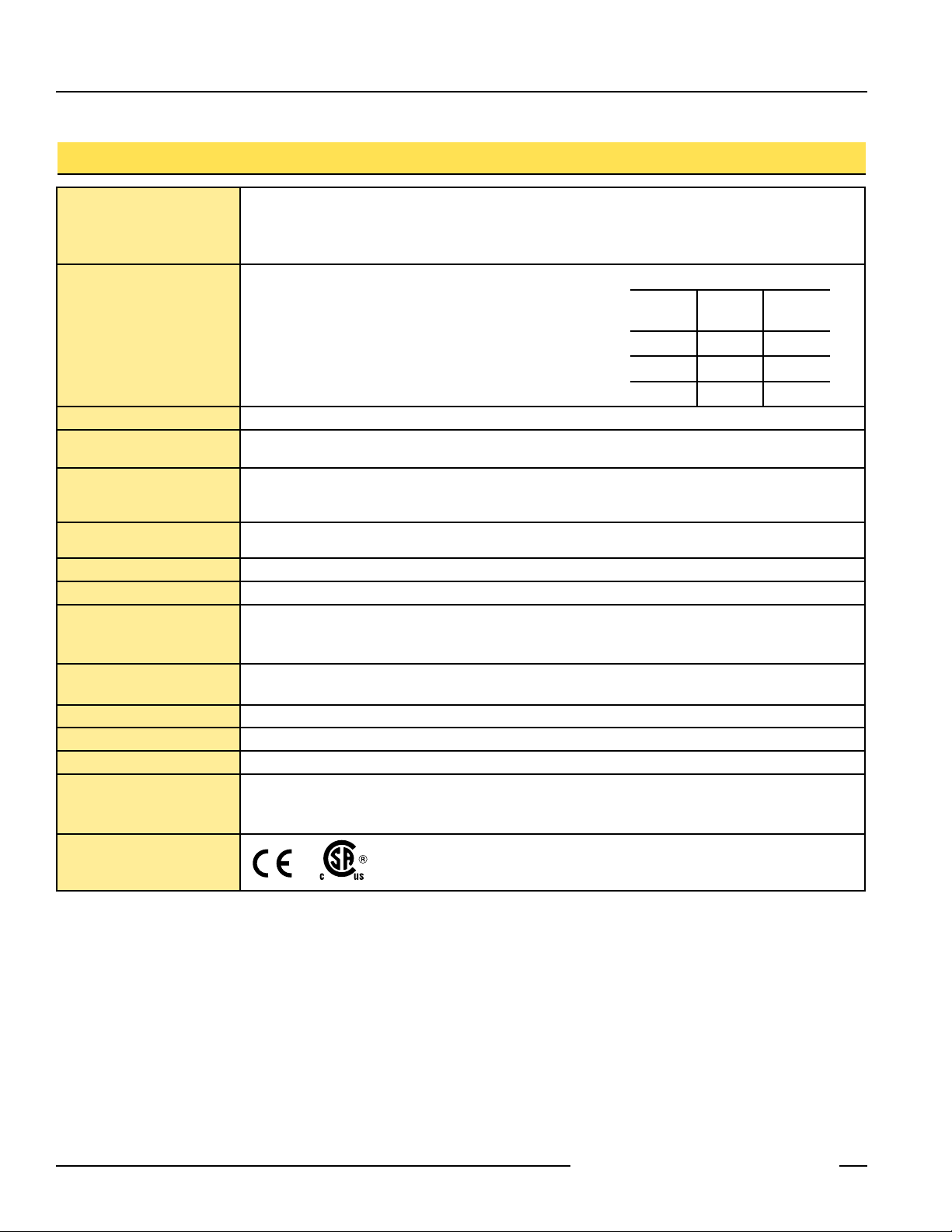
Specifications
Contact Rating 10A @ 24V ac, 10A @ 110V ac, 6A @ 230V ac
6A @ 24V dc
2.5 kV max. transient tolerance
NEMA A300 P300
European Rating Utilization categories: AC15 and DC13
Ui = 500V ac
Ith = 10A
Contact Material Silver-nickel alloy
Maximum Switching Speed 50 operations per minute
Recommended Rope Size 3 mm diameter steel rope (See Accessories, p. 10)
RP-LS42F-75L.. Series
40-60 Hz
U
V
24 10 6
110 10 1
230 6 0.4
Ie/AC-15
e
A
I
/DC-13
e
A
Maximum Rope Pull Length 75 m (245')
Short Circuit Protection 10 amp Slow Blow, 15 amp Fast Blow. Recommended external fusing or overload protection.
Mechanical Life 1 million operations
Wire Connections Screw terminals with pressure plates accept the following wire sizes –
Stranded and solid: 20 AWG (0.5 mm
Stranded: 20 AWG (0.5 mm
Cable Entry M20 x 1.5 threaded entrance
Adapter supplied to convert M20 x 1.5 to ½" - 14 NPT threaded entrance
Construction High-impact thermoplastic housing; zinc die-cast actuator
Environmental Rating NEMA 4, IEC IP67
Operating Conditions Temperature:
Weight RP-LS42F-75L: 0.48 Kg (1.05 lbs.)
RP-LS42F-75LE: 0.65 Kg (1.43 lbs.)
RP-LS42F-75LF: 0.65 Kg (1.43 lbs.)
Certifications
-25° to +70° C (-22° to +176° F)
2
) to 18 AWG (1.0 mm2) for two wires
2
) to 16 AWG (1.5 mm2) for one wire
8 P/N 67709 rev. A
Banner Engineering Corp. • Minneapolis, MN U.S.A.
www.bannerengineering.com • Tel: 763.544.3164
Page 9

Rope Pull Emergency Stop Switches –
88.0 mm
(3.46")
294.0 mm
(11.57")
256.0 mm
(10.08")
42.0 mm
(1.65")
45.0 mm
(1.77")
78.3 mm
(3.08")
5.0 mm
(0.20")
124.0 mm
(4.88")
224.0 mm
(8.82")
30.0 mm
(1.18")
78.3 mm
(3.08")
Dimensions
RP-LS42F-75L
RP-LS42F-75L.. Series
RP-LS42F-75LE
RP-LS42F-75LF
Banner Engineering Corp. • Minneapolis, MN U.S.A.
P/N 67709 rev. A 9
www.bannerengineering.com • Tel: 763.544.3164
Page 10
Rope Pull Emergency Stop Switches –
Spring breakage
protector cable
Spring breakage
protector cable
Thimble
Thimble
Clamp
Clamp
Turnbuckle Spring
Spring
Eye Bolt
Eye Bolt
Pulley
Pulley
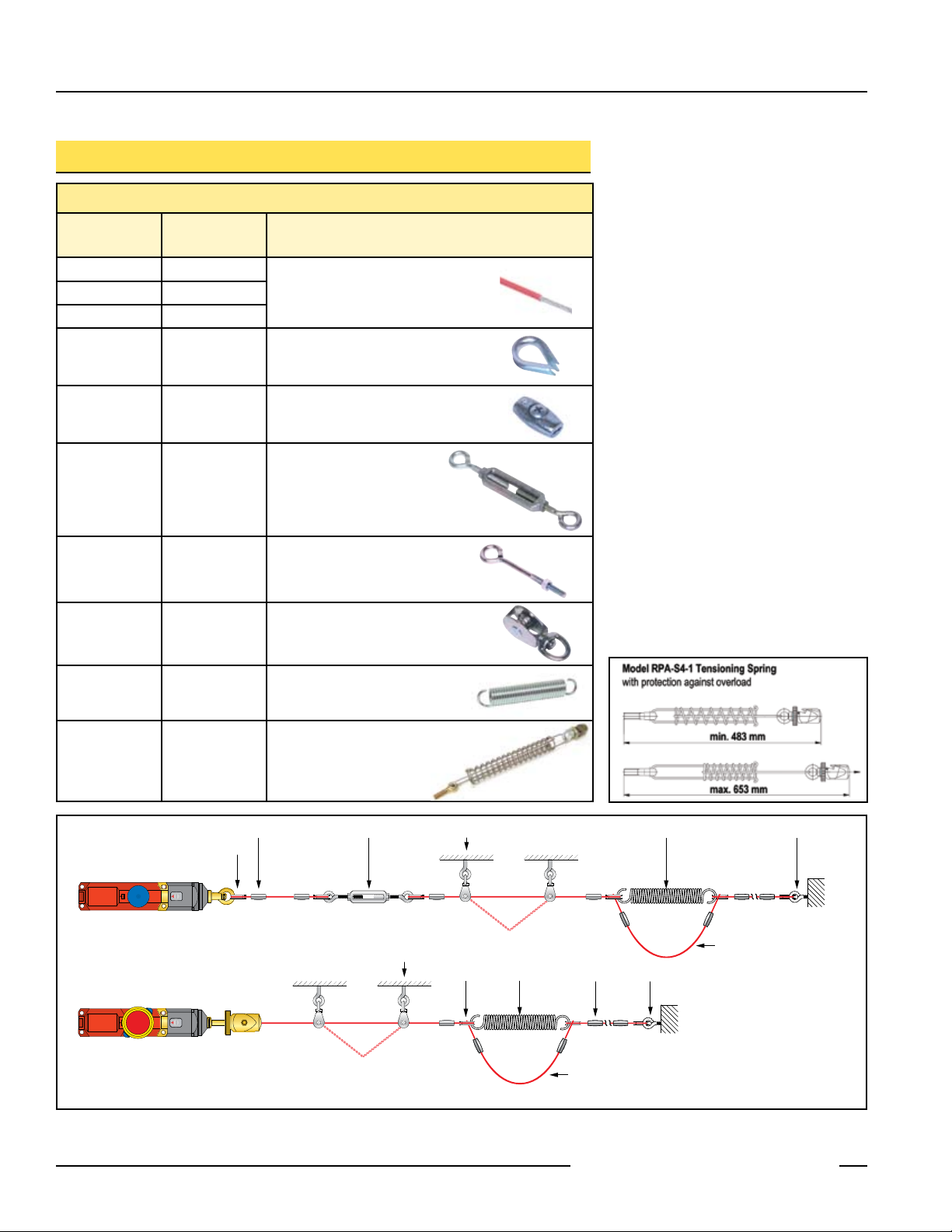
Accessories
Components for Wire Rope Assembly
Model
RPA-C2-10 10 m (33')
RPA-C2-20 20 m (66')
RPA-C2-80 80 m (264')
RPA-T2-4 4 pcs Thimble for 3 mm wire rope
RPA-CC2-4 4 pcs Clamp for 3 mm wire rope
RPA-TA1-1 1 pc #4 Turnbuckle
Package
Quantity
Description
3 mm steel wire rope with
0.25 mm red PVC jacket
(unterminated)
RP-LS42F-75L.. Series
RPA-EB1-1 1 pc
1/4"-20 Eye bolt
(3" bolt shaft)
RPA-P1-1 1 pc Pulley
RPA-S3-1 1 pc Tensioning spring
Tensioning spring with
RPA-S4-1 1 pc
built-in eye bolt, cable thimble,
clamping, tensioning, and
overload protection
NOTE: If model RPA-S4-1 tensioning spring is used, eliminate eye bolt, spring,
protector cable, clamp and thimble from versions shown here.
Figure 7. Wire rope assembly components
10 P/N 67709 rev. A
Banner Engineering Corp. • Minneapolis, MN U.S.A.
www.bannerengineering.com • Tel: 763.544.3164
Page 11

Rope Pull Emergency Stop Switches –
23.0 mm
(0.91")
M20 x 1.5
24.0 mm
(0.94")
1/2"-14 NPT
Internal Thread
O-ring
M20 x 1.5
25.0 mm
(0.98")
37.0 mm
(1.46")
Size Model
Used with
Switch Models
Accessories, continued
Cable Glands
For Cable
Diameters
RP-LS42F-75L.. Series
Dimensions
M20 x 1.5
Plastic
Size Model*
½"-14
NPT Plastic
*NOTE: One conduit adapter is supplied with each switch.
SI-QS-CGM20 All
Used with
Switch Models
SI-QS-M20 All
6.0 to 12.0 mm
(0.24" to 0.47")
Conduit Adaptors
Thread
Conversion
M20 x 1.5 to
½" -14 NPT
Dimensions
Banner Engineering Corp. • Minneapolis, MN U.S.A.
P/N 67709 rev. A 11
www.bannerengineering.com • Tel: 763.544.3164
Page 12

Rope Pull Emergency Stop Switches –
RP-LS42F-75L.. Series
WARRANTY: Banner Engineering Corp. warrants its products to be free from defects for one year. Banner Engineering Corp. will repair or replace,
free of charge, any product of its manufacture found to be defective at the time it is returned to the factory during the warranty period. This warranty
does not cover damage or liability for the improper application of Banner products. This warranty is in lieu of any other warranty either expressed or
implied.
P/N 67709 rev. A
Banner Engineering Corp., 9714 Tenth Ave. No., Minneapolis, MN USA 55441 • Phone: 763.544.3164 • www.bannerengineering.com • Email: sensors@bannerengineering.com
 Loading...