

Page 1
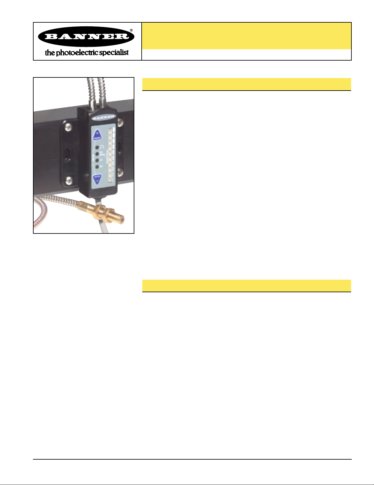
R55F Series Fiber-Optic Color Mark Sensors
For Plastic and Glass Fiber Optics
Printed in USA
05/01 P/N 57945 rev. B
R55F Series Sensor Features
• Outstanding color contrast sensitivity; detects 16 levels of gray scale.
• Depending on beam color, reliably detects the toughest color mark contrasts,
including 20% yellow against white.
• Fast, 50-microsecond response.
• Choose from infrared or one of four visible beam colors: red, blue, green and
white.
• Fibers mount in small and otherwise inaccessible areas.
• Easy push-button programming options include Static TEACH, Static Single-Point
TEACH, Dynamic TEACH and Remote TEACH; plus manual sensitivity adjustment.
• Non-volatile memory.
• Glass fiber models function well in harsh environments typically associated with
printing processes.
• Plastic fiber models function well in applications that require repeated flexing of
the fibers.
• Fibers install quickly without tools.
• Bipolar (NPN/PNP) outputs with three Delay settings (0, 20 or 40 milliseconds).
• Choice of integral cable or QD connector models.
• Mounts flat or to 35 mm DIN rail; two brackets included with sensor (one for
angle mount, one for flat mount).
R55F Series Sensor Overview
The R55F Fiber-Optic Sensor was developed to provide simplicity of operation and
access to tight areas for color mark (registration) sensing applications. The R55F is a
technological advancement from earlier R55 models.
R55F sensors feature TEACH mode sensitivity adjustment, by presenting the light and
the dark sensing conditions to the sensor. In addition, sensitivity may be fine-tuned at
any time by simply clicking the “+” or “-” buttons on the sensor. The ten-element signal
strength light bar clearly displays the relative received signal strength.
The bipolar (one NPN and one PNP) outputs may be programmed to include a 20 or
40-millisecond pulse stretcher (OFF Delay), if required. Both TEACH mode sensitivity
adjustment and output SETUP are accomplished using the push-buttons on the sensor,
or by supplying input pulses via the Remote Teach input.
TEACH mode has two options: Static TEACH and Dynamic TEACH. Static TEACH is
used to manually set the two sensing conditions individually or to program a specific
condition to be sensed (single-point TEACH). Dynamic TEACH provides a means for
teaching a series of conditions on-the-fly; the R55F “averages” the sensing events and
automatically sets (and periodically updates via the adaptive threshold feature) the
switch point between light and dark conditions.
Page 2
R55F Series Fiber-Optic Color Mark Sensors
page
2
Banner Engineering Corp. • Minneapolis, U.S.A.
www.bannerengineering.com • Tel: 763.544.3164
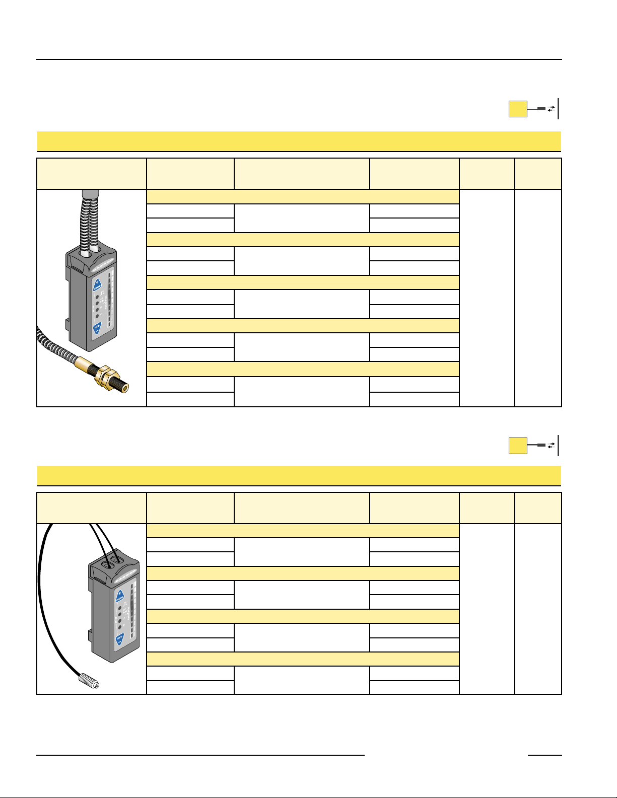
R55F Series Glass Fiber-Optic Sensor Models
R55F Series Plastic Fiber-Optic Sensor Models
* 9m (30') cables are available by adding suffix “W/30” to the model number of any cabled sensor (e.g., R55FV W/30). A model with a QD
connector requires a mating cable (see page 11).
Advantages of glass fiber optics for color mark sensing:
• Randomly mixed bifurcated fiber bundles produce the best optics for color mark sensing.
• Bundle of small fibers may be shaped at sensing end tip to match the color mark shape.
• Best chemical resistance.
Visible Red, 650 nm
Visible Green, 525 nm
Visible Blue, 475 nm
Visible White, 450-650 nm
Infrared, 880 nm
Visible Red, 650 nm
Visible Green, 525 nm
Visible Blue, 475 nm
Visible White, 450-650 nm
Advantages of plastic fiber optics for color mark sensing:
• Plastic fibers may be repeatedly flexed.
• Low cost.
• Most models may be cut to fit in the field.
Model
Number
Maximum Sensing Distance
For black-to-white contrast
Cable*
Supply
Voltage
Output
Type
Visible Red, 650 nm
10 to 30V dc
Bipolar
NPN/PNP
R55FP
0.040" dia. Fibers: 60 mm (2.4")
5-wire 2 m (6.5') cable
R55FPQ 5-pin Euro-style QD
Visible Green, 525 nm
R55FPG
0.040" dia. Fibers: 28 mm (1.1")
5-wire 2 m (6.5') cable
R55FPGQ 5-pin Euro-style QD
Visible Blue, 475 nm
R55FPB
0.040" dia. Fibers: 28 mm (1.1")
5-wire 2 m (6.5') cable
R55FPBQ 5-pin Euro-style QD
Visible White, 450 - 650 nm
R55FPW
0.040" dia. Fibers: 28 mm (1.1")
5-wire 2 m (6.5') cable
R55FPWQ 5-pin Euro-style QD
Model
Number
Maximum Sensing Distance
For black-to-white contrast
Cable*
Supply
Voltage
Output
Type
Visible Red, 650 nm
10 to 30V dc
Bipolar
NPN/PNP
R55FV
0.060" dia. Bundle: 28 mm (1.1")
0.125" dia. Bundle: 110 mm (4.3")
5-wire 2 m (6.5') cable
R55FVQ 5-pin Euro-style QD
Visible Green, 525 nm
R55FVG
0.060" dia. Bundle: 12 mm (0.5")
0.125" dia. Bundle: 50 mm (2.0")
5-wire 2 m (6.5') cable
R55FVGQ 5-pin Euro-style QD
Visible Blue, 475 nm
R55FVB
0.060" dia. Bundle: 12 mm (0.5")
0.125" dia. Bundle: 50 mm (2.0")
5-wire 2 m (6.5') cable
R55FVBQ 5-pin Euro-style QD
Visible White, 450 - 650 nm
R55FVW
0.060" dia. Bundle: 12 mm (0.5")
0.125" dia. Bundle: 50 mm (2.0")
5-wire 2 m (6.5') cable
R55FVWQ 5-pin Euro-style QD
Infrared, 880 nm
R55F
0.060" dia. Bundle: 40 mm (1.6")
0.125" dia. Bundle: 140 mm (5.5")
5-wire 2 m (6.5') cable
R55FQ 5-pin Euro-style QD
Page 3
R55F Series Fiber-Optic Color Mark Sensors
page
3
Banner Engineering Corp. •
Minneapolis, U.S.A.
www.bannerengineering.com • Tel: 763.544.3164
B
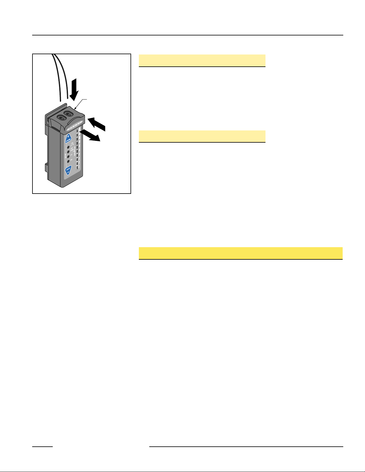
Figure 1. Installing fibers into the R55F
Series sensor
Plastic fibers
shown; procedure
is identical for
glass fibers
Glass Fiber Installation Procedure:
1) Check to see that a rubber o-ring is pre-installed on each fiber control end.
2) Slide the fiber clip to the open position (A).
3) Insert one fiber end into each port (B). Push firmly on the fiber ends to compress
the o-rings and align the grooves in the fiber ends with the slot in the fiber clip.
4) Slide the fiber clip back into place, locking the fibers into position (C).
Plastic Fiber Installation Procedure:
NOTE: R55F sensors accept 0.75, 1.0, and 1.5 mm (0.03", 0.04", and 0.06") core
diameter plastic fibers.
1) Cut the “control ends” (sensor ends) of the plastic fiber(s) to the desired length
per the procedure which accompanies the fiber assembly.
2) If not already done, separate bifurcated fibers by approximately 2" from the control
ends.
3) Slide the fiber clip to the open position (A).
4) Insert the fiber ends into each port and push them in as far as they will go (B).
5) Slide the fiber clip back into place, locking the fibers into position (C).
Fiber Optic Mounting Considerations
Mount the sensing end of the fiber optic assembly so that the light image is totally
contained within the boundaries of the color mark to be sensed. The light image is
made smaller by moving the sensing tip closer to the surface of the material to be
sensed.
When sensing marks on shiny (specular) materials, such as metal, plastic or glossy
paper, mount the sensing tip of the fiber at approximately 15° from perpendicular to
the material surface to minimize strong direct reflections.
Isolate the fiber mounting from vibration. Also, maintain mechanical stability of the
surface to be sensed (e.g., stabilize web flutter at the sensing point).
Fiber
Clip
C
A
Page 4
R55F Series Fiber-Optic Color Mark Sensors
page
4
Banner Engineering Corp. • Minneapolis, U.S.A.
www.bannerengineering.com • Tel: 763.544.3164
Using the R55F Series Sensor
RUN Mode
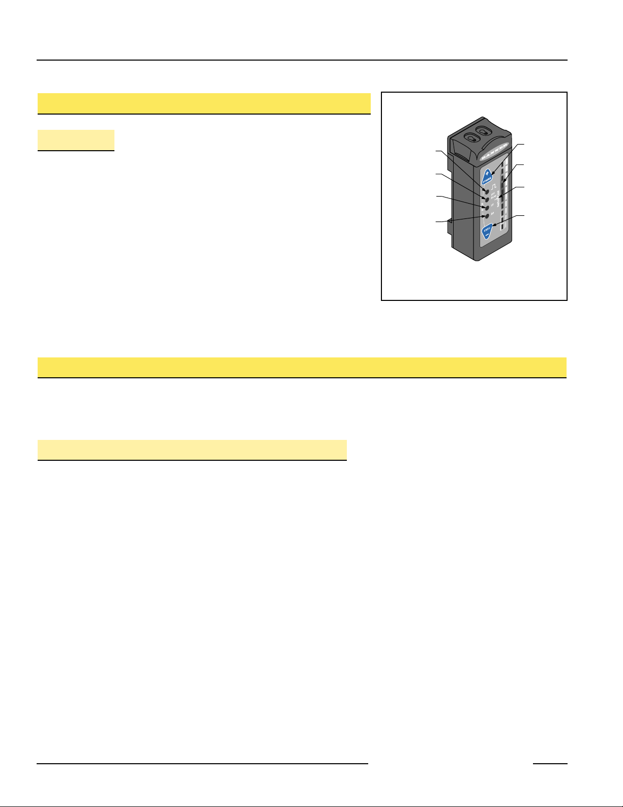
Normal operation of the R55F is called RUN mode. The LED indicators (see
Figure 2) operate as follows in RUN mode:
Output Conducting LED: ON when outputs are active
Delay Configuration Indicator LED: OFF No OFF Delay is programmed
ON 20 or 40-ms OFF Delay is programmed
Light Operate LED: ON to indicate Light Operate configuration
Dark Operate LED: ON to indicate Dark Operate configuration
(NOTE: Since either one of these is always ON when the sensor is operating, the
combined Light/Dark Operate LEDs also provide a functional Power-ON indication.)
10-Segment Light Bar: indicates signal strength, with respect to the sensing
threshold (“Switch Point”).
TEACH Modes
The sensitivity of the R55F may be quickly optimized by using one of two available TEACH modes: Static TEACH or Dynamic
TEACH. Either may be performed using the push buttons on the sensor, or remotely, using a remote switch or process controller
connected to the sensor’s gray wire(see page 8).Either a sensing window or a specific point may be taught.
Static TEACH
In Static TEACH mode, the sensor learns the light condition and the dark condition, each one time. Sensitivity is automatically set
to place the switch point midway between the two conditions. In addition, the condition taught first becomes the output ON
condition.
Sensitivity may be adjusted at any time when the sensor is in RUN mode by clicking the “+” and “-” buttons. Each click translates
to 1/2 segment on the signal strength light bar. For best sensing reliability, the light and dark conditions should register equally
distant from the switch point on the signal strength light bar.
Single-Point TEACH
The R55F sensor also may be taught a single specific target, using an alternate Static TEACH procedure. The sensor will sense
only the mark taught and will ignore signals both stronger and weaker. The sensitivity to the taught mark then may be adjusted up
or down.
To perform single-point TEACH, place the target in front of the sensor. Press and hold the “Static” button until the LO and DO
LEDs begin to flash, then double-click the Static button. If the single point was successfully taught, the two center sections of the
bar graph will flash.
Manually adjust the sensitivity by clicking either the “+” or “-” button; the bar graph will flash two segments centered about the
sensing point. If the sensitivity is increased (-), the two lighted segments will become closer together, and farther apart if the
sensitivity is decreased (+). If the segments do not flash while the sensitivity is being adjusted, the setting has reached its
maximum and cannot be adjusted further.
Figure 2. R55F Series sensor features
Output
Conducting
LED
Delay
Configuration
Indicator LED
(Light Operate)
(Dark Operate)
* Either LO or DO LED is ON
whenever sensor has power
and is in RUN mode
LO
LED*
DO
LED*
Dynamic
TEACH (+)
Push Button
10-Segment
Light Bar
Switch
Point
Static
TEACH (-)
Push Button
Page 5

Static Single-Point TEACH Procedure - Push Button
Static TEACH Procedure - Push Button
R55F Series Fiber-Optic Color Mark Sensors
page
5
Banner Engineering Corp. •
Minneapolis, U.S.A.
www.bannerengineering.com • Tel: 763.544.3164
Push Button Resulting Indicator Status
Press and hold STATIC button
until LO and DO indicators
alternately flash, then release
button.
LO and DO: Alternately flash green
: ON amber (indicating ready to
teach output ON condition)
Light Bar: Goes OFF
TEACH Condition #1
(Output ON state)
Present the output ON sensing
condition and single-click
STATIC button.
LO and DO: Alternately flash Green
: OFF (indicating ready to teach
output OFF condition)
Light Bar: Remains OFF
TEACH Condition #2
(Output OFF state)
Present the output OFF
sensing condition and singleclick STATIC button.
Contrast accepted: one of the ten
segments flashes for three seconds to
indicate relative contrast, and then the
sensor enters RUN mode.
Contrast too low: every other segment
flashes for three seconds to indicate low
contrast, and the sensor returns to TEACH
Condition #1.
SETUP
DOLOOFF
Delay
Switch Point
+
DYNAMIC
–
STATIC
Press and Hold ≥ 2 seconds
SETUP
DOLOOFF
Delay
Switch Point
+
DYNAMIC
–
STATIC
Single-click
SETUP
DOLOOFF
Delay
Switch Point
+
DYNAMIC
–
STATIC
Single-click
Signal Strength
Light Bar
Push Button Resulting Indicator Status
Press and hold STATIC button
until LO and DO indicators
alternately flash, then release
button.
LO and DO: Alternately flash green
: ON amber (indicating ready to
teach output ON condition)
Light Bar: Goes OFF
TEACH Condition to be
Sensed (Output ON state)
Present the output ON sensing
condition and double-click
STATIC button.
LO or DO: depending on condition of
taught
: OFF
Light Bar: Two center segments are lit
if TEACH was successful.
NOTES:
1) The sensor will return to RUNmode if either TEACH condition is not registered within 90 seconds. Also,
TEACH mode may be cancelled by pressing and holding the push button for ≥ 2 seconds. In either case, the
sensor will revert to the previous conditions taught (i.e., exit without save).
2) If the sensing conditions are accepted at the end of TEACH Condition #2, the signal strength light bar flashes
one of its ten segments for three seconds to indicate relative sensing contrast. The higher the flashing
segment, the higher the measured sensing contrast. High contrast relates directly to sensing reliability. Highcontrast sensing applications are most tolerant of sensing variables, such as web flutter or variations in color
mark color or print density.
See page 8 for Remote
TEACH procedures
Press and Hold ≥ 2 seconds
–
DOLOOFF
Switch Point
+
Delay
DYNAMIC
SETUP
STATIC
Double-click
DYNAMIC
SETUP
STATIC
–
DOLOOFF
Switch Point
+
Delay
Page 6

Dynamic TEACH
Dynamic TEACH is used to program sensitivity during actual machine run conditions. During
Dynamic TEACH, the R55F samples many color marks against their background material and
automatically sets the sensitivity at the optimum level. Dynamic TEACH activates the sensor’s
adaptive threshold system, which continuously tracks minimum and maximum signal levels, and
automatically maintains centering of the switch point between the light and dark conditions. The
adaptive threshold system remains in effect during RUN mode to automatically adjust for changes
in the light or the dark conditions.
When Dynamic TEACH mode is used to program sensitivity, the output ON state must be assigned
to either the light or dark condition using the SETUP mode (see page 7).
Sensitivity may be adjusted at any time when the sensor is in RUN mode by clicking the “+” and “-”
buttons. However, when a manual adjustment is made, the adaptive threshold system is disabled
(cancelled).
Dynamic TEACH Procedure - Push button
R55F Series Fiber-Optic Color Mark Sensors
page
6
Banner Engineering Corp. • Minneapolis, U.S.A.
www.bannerengineering.com • Tel: 763.544.3164
Push Button Resulting Indicator Status
Press and hold DYNAMIC
button until LO and DO
indicators alternately flash.
LO and DO: Alternately flash green
: OFF
Light Bar: Goes OFF
Continue depressing the
DYNAMIC button while
sampling light and dark
sensing conditions.
LO and DO: Alternately flash green
: OFF
Light Bar: Remains OFF
Release the DYNAMIC button
when finished sampling light
and dark sensing conditions.
Contrast accepted: one of the ten
segments flashes for three seconds to
indicate relative contrast, and the sensor
enters RUN mode.
Contrast too low: five light bar segments
flash for three seconds to indicate low
contrast, and sensor reverts to the
previously taught conditions.
NOTES:
1) If the sensing conditions are accepted at the end of Dynamic TEACH, the signal strength light bar flashes one
of its ten segments for three seconds to indicate relative sensing contrast. The higher the flashing segment,
the higher the measured sensing contrast. High contrast relates directly to sensing reliability. High contrast
sensing applications are most tolerant of sensing variables, such as web flutter or variations in color mark
color or print density.
2) If the sensor does not measure enough contrast at the end of Dynamic TEACH, every other segment of the
signal strength light bar flashes in unison for three seconds to warn of unacceptably low contrast, and the
sensor returns to RUN mode with its previously taught conditions.
See page 8 for Remote
TEACH procedures
Press and Hold ≥ 2 seconds
DYNAMIC
SETUP
STATIC
–
Continue to Depress
While Sensor Samples
Light and Dark Conditions
STATIC
–
STATIC
–
DOLOOFF
Switch Point
SETUP
DOLOOFF
Switch Point
SETUP
DOLOOFF
Switch Point
Delay
Delay
Release
Delay
+
DYNAMIC
+
DYNAMIC
+
Page 7

R55F Series Fiber-Optic Color Mark Sensors
page
7
Banner Engineering Corp. •
Minneapolis, U.S.A.
www.bannerengineering.com • Tel: 763.544.3164
SETUP Mode
SETUP mode is used to configure sensor output response for:
- Light or Dark operate
- 20- or 40-millisecond pulse stretcher (OFF delay), if required.
It will be necessary to access SETUP mode only if the settings which result from
TEACH mode programming are not the settings required for the application. The
status LEDs indicate the output response configuration when the sensor is in RUN
mode, as follows:
- LO indicator ON = output is light operate
- DO indicator ON = output is dark operate
- OFF Delay indicator ON = either 20- or 40-millisecond delay is programmed
- OFF Delay indicator OFF = no output delay is programmed
To change the output response settings;
1) Press and hold BOTH push buttons until the signal strength light bar turns OFF.
2) Click EITHER push button to toggle through the six possible settings
indicated as follows:
Figure 3. SETUP mode
Output Configuration
Delay
IndicatorLOIndicatorDOIndicator
Light operate with no delay
OFF ON OFF
Light operate with 20 ms delay
Flashing ON OFF
Light operate with 40 ms delay
ON ON OFF
Dark operate with no delay
OFF OFF ON
Dark operate with 20 ms delay
Flashing OFF ON
Dark operate with 40 ms delay
ON OFF ON
3) Press and hold both push buttons until the signal strength light bar turns ON,
indicating return to RUN mode.
NOTE: If SETUP mode programming is interrupted and remains inactive for 30
seconds, the sensor returns to RUN mode with the most recent settings
(i.e., exit and save current selection).
Press and Hold
Both Push Buttons
DYNAMIC
SETUP
STATIC
+
OFF
Delay
LO
Switch Point
DO
–
Page 8

R55F Series Fiber-Optic Color Mark Sensors
page
8
Banner Engineering Corp. • Minneapolis, U.S.A.
www.bannerengineering.com • Tel: 763.544.3164
Remote Programming
The gray wire of the R55F may be connected to a remote switch or to a process
controller to:
- Set sensitivity via either Static or Dynamic TEACH mode
- Set output response via SETUP mode
- Disable the push button functions
A remote programming switch is connected between the gray wire and dc common (see
Hookup diagrams on page 11). The switch may be either a normally-open contact, or an
open-collector NPN transistor with its emitter connected to dc common.
Remote programming is accomplished using a specified sequence of input pulses.
The duration of each pulse is defined as:
0.04 seconds < T < 0.8 seconds (40 ms < T< 800 ms)
Remote Static TEACH Mode
1) Present the Output ON condition to the fiber sensing end and pulse the Remote
TEACH input once.
2) Wait at least 0.8 seconds, present the Output OFF condition, and pulse the Remote
TEACH input once.
If sensing contrast is adequate, the sensor flashes one segment of the signal strength
light bar for 3 seconds to indicate relative contrast, and then enters RUN mode.
If contrast is too low, the sensor flashes five segments of the signal strength light bar
in unison to warn of unacceptably low contrast, and returns to re-teach the Output ON
condition (Step 1).
Remote Static Single-Point TEACH
The single-point TEACH may also be performed using the remote wire. Present the
target and single-click the remote wire. Wait for at least 0.8 second, then double-click
the remote wire. If the TEACH is successful, the sensor will flash the middle two LEDs
of the bar graph, and return to RUN mode.
Remote Dynamic TEACH Mode
1) Hold the TEACH input low for > 2 seconds
2) Continue holding the TEACH input low while presenting light and dark sensing
conditions. Open switch when finished teaching.
If sensing contrast is adequate, the sensor flashes one segment of the signal strength
light bar for 3 seconds to indicate relative contrast, and then enters RUN mode.
If contrast is too low, the sensor flashes five segments of the signal strength light bar
in unison to warn of unacceptably low contrast, and returns to RUN mode with its
previously taught conditions.
Figure 4. Input pulse timing
Figure 5. Static TEACH mode
Figure 6. Static Single-Point TEACH mode
Figure 7. Dynamic TEACH mode
0.04 < T < 0.8 sec
Switch Open
Switch Closed
to dc common
Present
Output ON
Condition
TT
Present
Output OFF
Condition
> 0.8 sec
Present
Output ON
Condition
TTT
> 0.8 sec
> 2 sec
Double-Click
T
TEACH Light
and Dark
Conditions
Page 9

R55F Series Fiber-Optic Color Mark Sensors
page
9
Banner Engineering Corp. •
Minneapolis, U.S.A.
www.bannerengineering.com • Tel: 763.544.3164
Remote SETUP Mode
1) To enter SETUPmode, pulse once, wait 0.04 to 0.8 seconds, then pulse again.
2) Wait > 0.8 seconds, then enter sequential pulses to toggle between the six
output configuration choices (see page 7). Spacing between sequential pulses
must be > 0.8 seconds.
3) To exit SETUPmode, hold the TEACH input low for > 2 seconds.
Locking Out (Disabling) the Push Buttons
Pulse four times to disable (or to re-enable) the push buttons.
Figure 8. SETUP mode
Figure 9. Push button lockout
R55F Series Sensor Dimensions
TTTT
Two pulses
to Enter
SETUP
> 0.8 sec
> 0.8 sec
Sequential
pulses to toggle
between configuration choices
TT
T
T
T
TT
Pulse four times to enable
or disable push button
etc.
TT
> 0.8 sec
Plastic Fiber
10.0 mm
(0.39")
35.0 mm
(1.40")
30.0 mm
(1.18")
24.5 mm
(0.97")
Glass Fiber
25.0 mm
(0.99")
12.9 mm
(0.51")
12.9 mm
(0.51")
85.4 mm
(3.36")
11.6 mm
(0.46")
10.0 mm
(0.39")
Quick-Disconnect
Models
+
DYNAMIC
SETUP
STATIC
–
OFF
Delay
LO
DO
Switch Point
4.5 mm
(0.18")
Cabled
Models
+
DYNAMIC
SETUP
STATIC
–
OFF
Delay
LO
DO
Switch Point
Page 10

R55F Series Fiber-Optic Color Mark Sensors
page
10
Banner Engineering Corp. • Minneapolis, U.S.A.
www.bannerengineering.com • Tel: 763.544.3164
R55F Series Sensor Specifications
Supply Input 10 to 30V dc (10% maximum ripple) at less than 70 mA, exclusive of load
Supply Protection Circuitry Protected against reverse polarity and transient voltages
Output Rating
150 mA max each output @ 25°C (derate ≈ 1 mA per °C increase)
OFF-state leakage current: < 5 µA @ 30V dc
ON-state saturation voltage: PNP Output < 1V @ 10 mA and 1.5V @ 150 mA
NPN Output < 200 mV @ 10 mA and 1V @ 150 mA
Output Response
50 microseconds
NOTE: 100 millisecond delay on power-up; outputs do not conduct during this time.
Indicator LEDs
10-segment (green) light bar indicates signal strength
Light Operate (green)
Dark Operate (green)
Outputs Conducting (yellow)
OFF Delay (green): SETUP Mode: OFF — no delay RUN Mode: OFF — no delay
Flashing — 20 ms delay ON — 20 or 40 ms Delay
ON — 40 ms delay
Construction
Housing: Black ABS/polycarbonate blend; nylon fiber clip
mounts to standard 35 mm DIN rail
1 stainless steel right angle bracket and 1 PBT polyester bracket for mounting to flat surfaces also included
with sensor
Environmental Rating IEC IP67; NEMA 6
Connections
Power: 2 m or 9 m PVC-jacketed 5-conductor cable or 5-pin Euro-style quick-disconnect (QD) connector
Fibers: Fiber clip (no tool required)
Operating Conditions
Temperature: -10° to +55° C (+14° to 131° F)
Maximum Relative Humidity: 90% at 50° C (non-condensing)
Application Notes
• Do not mount the fiber tip directly perpendicular to shiny surfaces; position it at approximately a 15° angle
in relation to the sensing target
• Minimize web or product “flutter” whenever possible to maximize sensing reliability
Output Configuration Bipolar (NPN and PNP)
Output Protection Protected against false pulse on power-up and continuous overload or short-circuit of outputs.
Adjustments
(see pages 4 - 9)
Using push buttons (“+” Dynamic and “-” Static):
Manually adjust Switch Point using “+” or “-” buttons
Dynamic TEACH (teach on-the-fly) sensitivity adjustment
Static TEACH sensitivity adjustment
Light operate/Dark operate
OFF Delay select: 0 milliseconds, 20 milliseconds or 40 milliseconds
Using Remote TEACH input (gray wire):
Dynamic TEACH (teach on-the-fly) sensitivity adjustment
Static TEACH sensitivity adjustment
Light operate/Dark operate
OFF Delay select: 0 milliseconds, 20 milliseconds or 40 milliseconds
Push button lockout for security
Page 11

R55F Series Fiber-Optic Color Mark Sensors
page
11
Banner Engineering Corp. •
Minneapolis, U.S.A.
www.bannerengineering.com • Tel: 763.544.3164
R55F Series Sensor Hookups
Cabled Models
Quick-Disconnect Models
Mounting Brackets
Both brackets are included with sensor.
SMBR55FRA
• Side-mounting bracket
• 19 ga stainless steel
SMBR55F01
• Flat-mounting bracket
• Molded PBT polyester
Quick-Disconnect (QD) Cables
5-Pin Euro
MQDC1-506
MQDC1-515
MQDC1-530
MQDC1-506RA
MQDC1-515RA
MQDC1-530RA
2 m (6.5')
5 m (15')
9 m (30')
2 m (6.5')
5 m (15')
9 m (30')
Style Model Length Connector
Straight
Straight
Straight
Right-angle
Right-angle
Right-angle
bn
bu
wh
bk
gy
40.0 mm
(1.58")
4.5 mm
(0.18")
Load
Load
Remote Teach
2x ø5.4 mm
(0.21")
35.0 mm
(1.38")
+
10-30V dc
–
20.0 mm
(0.79")
3.5 mm
(0.14")
65.0 mm
(2.56")
29.5 mm
(1.16")
bn
bu
wh
Load
bk
Load
gy
Remote Teach
15.0 mm
(0.59")
4x R2.5
(0.10")
7.2 mm
(0.28")
4x 5.0 mm
(0.20")
+
10-30V dc
–
6.0 mm
(0.24")
35.0 mm
(1.40")
50.8 mm
(2.00")
2.5 mm
(0.10")
4.5 mm
(0.18")
10.0 mm
(0.40")
7.5 mm
(0.30")
30.4 mm
(1.20")
50.8 mm
(2.00")
64.0 mm
(2.52")
Brown Wire
Black Wire
White Wire
Blue Wire
Gray Wire
Page 12

R55F Series Glass and Plastic Fiber-Optic Color Mark Sensors
WARRANTY: Banner Engineering Corp. warrants its products to be free from defects for one year. Banner Engineering Corp. will repair or
replace, free of charge, any product of its manufacture found to be defective at the time it is returned to the factory during the warranty
period. This warranty does not cover damage or liability for the improper application of Banner products. This warranty is in lieu of any
other warranty either expressed or implied.
WARNING . . . Not To Be Used for Personnel Protection
Never use these products as sensing devices for personnel protection. Doing so could lead to serious injury or death.
These sensors do NOT include the self-checking redundant circuitry necessar y to allow their use in personnel safety
applications. A sensor failure or malfunction can cause either an energized or de-energized sensor output condition. Consult your current
Banner Safety Products catalog for safety products which meet OSHA, ANSI and IEC standards for personnel protection.
Euro-Style Field-Wireable Connectors
Contacts: Gold-plated; 4-pin models rated 250V ac/dc max., 4 A max.; 5-pin models rated 50V ac/dc max., 4A max.
Cable Diameter: 4.0 to 5.0 mm (0.16 to 0.20")
Temperature: -25° to +90°C (-13° to +194°F)
Environmental Rating: NEMA 6P, IP 67
Style
5-Pin
Right-angle
FIC-M12M5A
5-Pin
Straight
FIC-M12M5 Male
Male
FIC-M12F5A Female
FIC-M12F5 Female
Model Gender
Dimensions Pin-out
Banner Engineering Corp., 9714 Tenth Ave. No., Minneapolis, MN 55441 • Phone: 763.544.3164 • www.bannerengineering.com • Email: sensors@bannerengineering.com
15.0 mm
(0.59")
15.0 mm
(0.59")
30.5 mm
(1.20")
60 mm
(2.4")
10 mm
(0.4")
M12 x 1
60 mm
(2.4")
10 mm
(0.4")
M12 x 1
41 mm
(1.6")
M12 x 1
15.0 mm
(0.59")
20 mm
(0.8")
20 mm
(0.8")
20 mm
(0.8")
20 mm
(0.8")
!
 Loading...