

Page 1
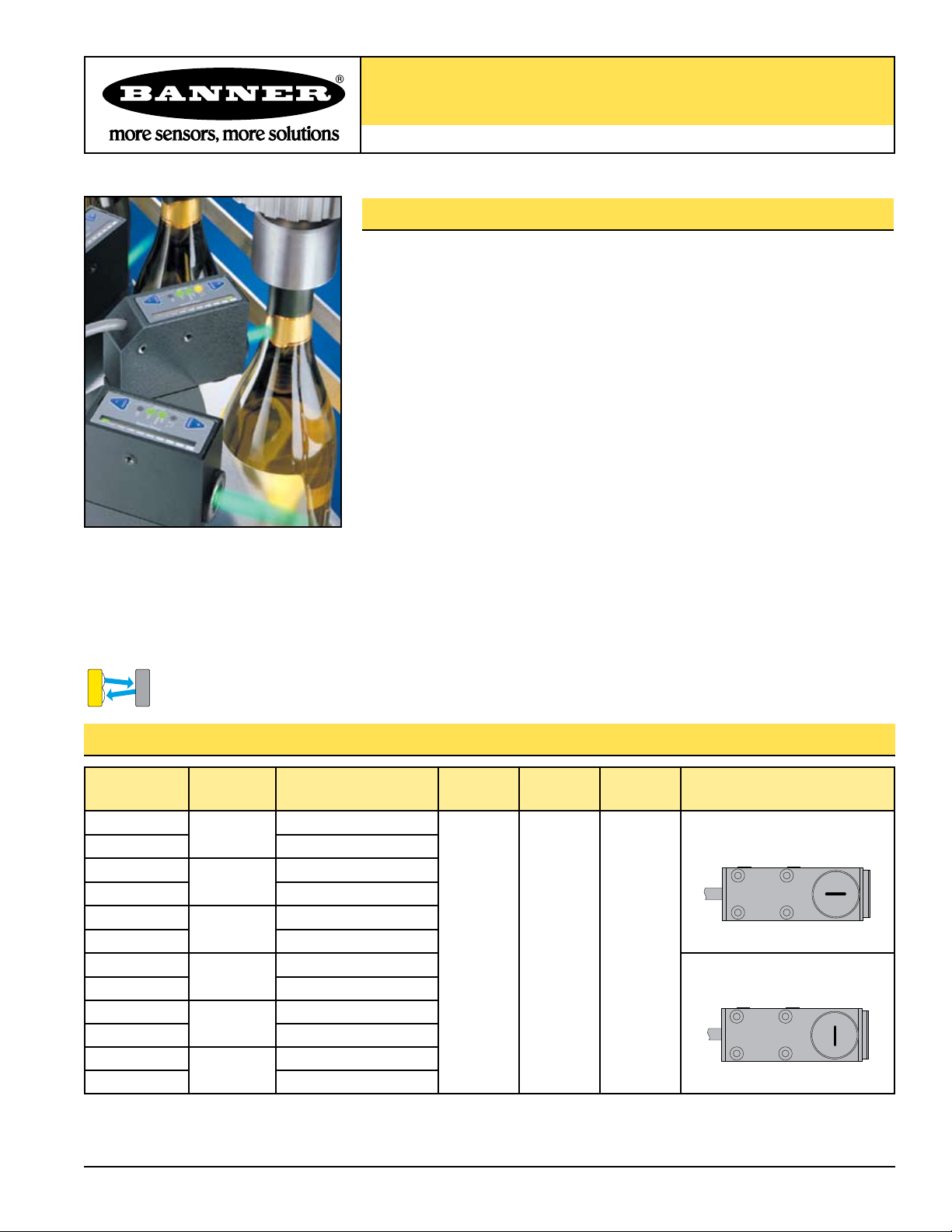
R55 Expert™ Color Mark Sensors
Parallel to sensor length
Perpendicular to sensor length
Perpendicular to sensor length
CONVERGENT
Color Registration Mark Sensor with Solid-State Light Source
Features
• Outstanding color contrast sensitivity; detects 16 levels of gray scale.
• Reliable detection of the toughest color mark contrasts, including 20% yellow
against white
• Three sensing beam colors: blue, green and white, depending on model
• Fast, 50-microsecond response
• Easy-to-set automatic
Expert-style configuration options: Static and Dynamic TEACH
and Window SET, plus Manual Adjust for fine tuning via push button or remote input
• Non-volatile memory
• Ten-element light bar for clear display of received signal strength
• Fixed-convergent sensing at 10 ±3 mm (0.39" ±0.12")
• Rectangular 1.2 mm x 3.8 mm (0.05" x 0.15") sensing image at 10 mm from the lens
• Horizontal or vertical sensing image, depending on model (see table below)
• Rugged zinc alloy die-cast housing with high-quality acrylic lens suitable for food
processing applications; rated IP67, NEMA 6
• Bipolar (NPN/PNP) discrete outputs with three delay settings (0, 20 or 40 ms)
• 0 to 10 mA analog output; value provides an indication of signal strength.
• Integral cable or QD connector, depending on model
Models Beam Color Cable* Focus
R55ECG1
R55ECG1Q 6-pin Euro-Style QD
R55ECB1
R55ECB1Q 6-pin Euro-Style QD
R55ECW1
R55ECW1Q 6-pin Euro-Style QD
R55ECG2
R55ECG2Q 6-pin Euro-Style QD
R55ECB2
R55ECB2Q 6-pin Euro-Style QD
R55ECW2
R55ECW2Q 6-pin Euro-Style QD
* 9 m (30') cables are available by adding suffix “W/30” to the model number of the cabled version (e.g., R55ECG1 W/30). A model with a QD
connector requires an accessory mating cable. See page 12.
Printed in USA 12/06 P/N 59574 rev. B
Green
525 nm
Blue
475 nm
White
450-650 nm
Green
525 nm
Blue
475 nm
White
450-650 nm
6-wire 2 m (6.5')
6-wire 2 m (6.5')
6-wire 2 m (6.5')
6-wire 2 m (6.5')
6-wire 2 m (6.5')
6-wire 2 m (6.5')
Models
10 mm
(0.39")
Supply
Voltage
10-30V dc
Output
Type
Bipolar
NPN/PNP
and
Analog
0-10 mA
Sensing Image Orientation
Page 2
R55 Expert™ Color Mark Sensors
SETUP
DO
LO
OFF
Delay
Switch Point
+
DYNAMIC
–
STATIC
Dynamic (+)
Push Button
Switch Point
10-Segment
Bargraph Display
Static (–)
Push Button
DO
(Dark Operate) LED*
* Either LO or DO LED is ON
Whenever sensor has power
and is in RUN Mode
LO
(Light Operate) LED*
Delay Configuration
Indicator LED
Output Conducting
LED
Overview
R55 Expert (R55E) offers maintenance-free, solid-state reliability for all color contrasts found
in common product and material registration applications. Fast 50-microsecond sensing
response produces excellent registration repeatability, even in ultra-high-speed applications.
This fast response, coupled with the small 1.2 x 3.8 mm (0.05" x 0.15") sensing image, allows
color marks to be made small and inconspicuous, while being reliably sensed.
The construction of the R55E is extremely robust, with a die-cast metal housing, plastic
optics, and IP67 and NEMA 6 leakproof design for harsh sensing environments. The sensor's
10-segment bargraph display and the individual indicator LEDs provide easy configuration
and status monitoring.
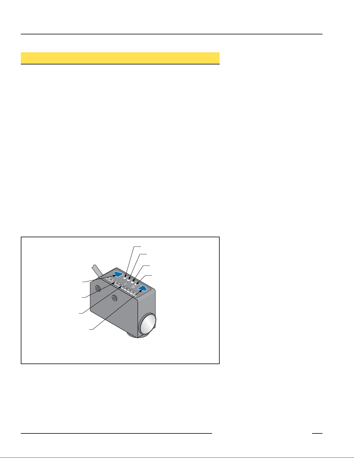
Indicators
The LED indicators (see Figure 1) operate as follows in RUN mode (normal operation):
Output Conducting LED: ON when outputs are active
Delay Configuration Indicator LED: OFF No OFF-delay is programmed
ON 20- or 40-ms OFF-delay is programmed
Light Operate LED: ON to indicate Light Operate configuration
Dark Operate LED: ON to indicate Dark Operate configuration
(NOTE: Since either one of these is always ON when the sensor is operating, the
combined Light/Dark Operate LEDs also provide a functional Power-ON indication.)
10-Segment Bargraph Display: indicates signal strength, with respect to the sensing
threshold (“switchpoint”).
Figure 1. R55E Series sensor features
2 P/N 59574 rev. B
Banner Engineering Corp. • Minneapolis, MN U.S.A.
www.bannerengineering.com • Tel: 763.544.3164
Page 3

R55 Expert™ Color Mark Sensors
Sensor Configuration
Sensor configuration is accomplished via TEACH, SET and SETUP modes. After the
sensing parameters are defined (using either TEACH or SET mode), SETUP mode may
be used to enable the delay or to change the light/dark operate status. Manual Adjust
may be used to fine-tune the thresholds (see page 7). Two push buttons, Dynamic
(+) and Static (-), or the remote wire, may be used to access and set the sensing
parameters. The ten-element signal strength bargraph display clearly displays the relative
received signal strength.
Sensor sensitivity may be configured using any of three methods. A single switching
threshold may be achieved using either Dynamic (on-the-fly) or Static TEACH, or Window
SET may be used to define a sensing window, centered on a single sensing condition.
The discrete bipolar (one NPN and one PNP) outputs may be programmed in SETUP
mode to include a 20- or 40-millisecond pulse stretcher (OFF-delay), if required. A
third, dedicated, 0 to 10 milliamp analog output may be used for applications such as
measuring or monitoring of surface brightness or texture.
Both sensing sensitivity and output setup are accomplished either by using the sensor push
buttons, or by supplying input pulses via the remote input.
Remote Configuration
The remote configuration function may be used to configure the sensor remotely or to
disable the push buttons for security. Connect the gray wire of the sensor to ground
(0V dc), with a remote programming switch connected between them. Pulse the remote
line according to the diagrams in the configuration procedures. The duration of the
individual pulses is equal to the value T:
0.04 seconds ≤ T ≤ 0.8 seconds
Returning to RUN Mode
Some TEACH and SET modes may be exited after the 90-second time-out or by exiting
the process:
• In Static TEACH or Window SET mode, press and hold the Static (-) button (or hold the
remote line) for 2 seconds. The sensor returns to RUN mode without saving any new
settings.
SETUP mode may be exited after the 30-second time-out or by exiting the process:
• In SETUP mode, press and hold both the Static (-) and Dynamic (+) buttons (or hold
the remote line) for 2 seconds. The sensor returns to RUN mode and saves the current
setting.
Banner Engineering Corp. • Minneapolis, MN U.S.A.
P/N 59574 rev. B 3
www.bannerengineering.com • Tel: 763.544.3164
Page 4
R55 Expert™ Color Mark Sensors
+
DYNAMIC
–
STATIC
+
DYNAMIC
+
DYNAMIC
–
STATIC
–
STATIC
+
DYNAMIC
+
DYNAMIC
–
STATIC
–
STATIC
T
T T
T
T T
T T
T
T
T T
T
T T
T T
T
Sensor positions
threshold midway
between taught conditions
Darkest
(no signal)
Most Light
(saturated
signal)
Output OFF Output ON
2nd Taught
Condition
1st Taught
Condition
Position
adjusted by
Manual Adjust
Static TEACH
• Establishes a single switching threshold
• Threshold position is adjustable using “+” and “-” buttons (Manual Adjust)
Static TEACH is the traditional setup method, used when two conditions can be
presented by the user. The sensor locates a single sensing threshold (the switchpoint)
midway between the two taught conditions, with the Output ON condition on one side,
and the Output OFF condition on the other (see Figure 2).
The first condition taught is the ON condition. The Output ON and OFF conditions can be
reversed by changing Light/Dark Operate status in SETUP mode (see page 7).
Static TEACH and Manual Adjust
Using Manual Adjust with Static TEACH moves the switching threshold. Sensitivity may
be adjusted at any time when the sensor is in RUN mode by clicking the “+” and “-”
buttons. Each click translates to 1/2 segment on the signal strength light bar. For best
sensing reliability, the light and dark conditions should register equally distant from the
switchpoint on the bargraph display.
Push Button
0.04 seconds ≤ “Click” ≤ 0.8 seconds
• Press and hold Static button
≥ 2 seconds until LO and DO
indicators alternately flash,
then release button.
Access
TEACH Mode
• Present the output ON
sensing condition.
• Single-click Static button.
Condition
TEACH Output ON
• No action required; sensor is ready
for 1st TEACH condition.
• Present output ON sensing
condition.
• Single-pulse the remote line.
Remote Line
0.04 seconds ≤ T ≤ 0.8 seconds
Push Button TEACH only:
LO and DO: Alternately flash green
: ON yellow
Light Bar: Goes OFF
LO and DO: Alternately flash green
: OFF
Light Bar: Remains OFF
Figure 2. Static TEACH (Light Operate
shown)
Result
(ready to teach output ON condition)
(ready to teach output OFF condition)
Condition
TEACH Output OFF
NOTES:
1. The sensor will return to RUN mode if either TEACH condition is not registered within 90 seconds. Also, TEACH mode may be cancelled by
pressing and holding the push button for ≥ 2 seconds. In either case, the sensor will revert to the previous conditions taught (i.e., exit without
save).
2. If the sensing conditions are accepted at the end of TEACH Output OFF Condition, the signal strength light bar flashes one of its ten segments
for three seconds to indicate relative sensing contrast. The higher the flashing segment, the higher the measured sensing contrast. High contrast
relates directly to sensing reliability. High-contrast sensing applications are most tolerant of sensing variables, such as web flutter or variations in
color mark color or print density.
4 P/N 59574 rev. B
• Present the output OFF
sensing condition.
• Single-click Static button.
• Wait 0.8 seconds.
• Present the output OFF sensing
condition.
• Single-pulse the remote line.
Contrast accepted: One light bar segment flashes for
three seconds to indicate relative contrast, and then
sensor enters RUN mode.
Contrast too low: Every other segment flashes for three
seconds to indicate low contrast, and the sensor returns
to TEACH Output ON Condition.
Banner Engineering Corp. • Minneapolis, MN U.S.A.
www.bannerengineering.com • Tel: 763.544.3164
Page 5

Sensor positions
threshold midway
between taught conditions
Sensor positions
threshold midway
between taught conditions
Darkest
(no signal)
Most Light
(saturated
signal)
Output OFF
Output ON
Darkest Taught
Condition
Lightest Taught
Condition
Position
adjusted by
Manual Adjust
Darkest
(no signal)
Most Light
(saturated
signal)
Output OFF Output ON
2nd Taught
Condition
1st Taught
Condition
Position
adjusted by
Manual Adjust
Figure 3. Dynamic TEACH (Light Operate
+
DYNAMIC
+
DYNAMIC
+
DYNAMIC
+
DYNAMIC
+
DYNAMIC
+
DYNAMIC
T
TTT
T
T T
T T T
T T
T T
T
T T
T T
T
T
TTT
T
T T
T T T
T T
T T
T
T T
T T
T
T
TTT
T
T T
T T T
T T
T T
T
T T
T T
T
shown)
R55 Expert™ Color Mark Sensors
Dynamic TEACH
• Teach on-the-fly
• Establishes a single switching threshold
• Threshold position is adjustable using “+” and “-” buttons (Manual Adjust)
Dynamic TEACH is used to configure the switching threshold during actual sensing
conditions. During Dynamic TEACH, the R55E takes multiple samples of the color mark
against its background material and automatically sets the threshold at the optimum level.
Dynamic TEACH activates the sensor’s adaptive threshold system, which continuously
tracks minimum and maximum signal levels, and automatically maintains centering of
the switchpoint between the light and dark conditions. The adaptive threshold system
remains in effect during RUN mode to automatically adjust for changes in the light or
the dark conditions. The adaptive routine saves to non-volatile memory at least once per
hour.
When Dynamic TEACH mode is used to configure sensitivity, the output ON state (light
or dark operate) will remain as it was last programmed. To change to either the light or
the dark condition, use SETUP mode (see page 7).
Dynamic TEACH and Manual Adjust
Sensitivity may be adjusted at any time when the sensor is in RUN mode by clicking the
“+” and “-” buttons. However, when a manual adjustment is made, the adaptive threshold
system is disabled (cancelled).
Access
TEACH Output ON
Return to
NOTE: If the sensing conditions are accepted at the end of Dynamic TEACH, the signal strength light bar flashes one of its ten segments for three
P/N 59574 rev. B 5
Push Button Remote Line Result
• Press and hold Dynamic button
≥ 2 seconds until LO and DO
indicators alternately flash.
TEACH Mode
• Continue depressing the
Dynamic button while
sampling light and dark
sensing conditions.
and OFF Condition
• Release the Dynamic button when
finished sampling
light and dark sensing
conditions.
Run Mode
seconds to indicate relative sensing contrast. The higher the flashing segment, the higher the measured sensing contrast. High contrast
relates directly to sensing reliability. High contrast sensing applications are most tolerant of sensing variables, such as web flutter or
variations in color mark color or print density.
Banner Engineering Corp. • Minneapolis, MN U.S.A.
www.bannerengineering.com • Tel: 763.544.3164
• Hold remote line low (to ground)
> 2 seconds.
• Present Output ON and OFF
sensing conditions.
• Continue to hold remote line low.
• Release remote line switch.
LO and DO: Alternately flash green
: OFF
Light Bar: Remains OFF
LO and DO: Alternately flash green
: OFF
Light Bar: Remains OFF
Contrast accepted: One light bar segment flashes for
three seconds to indicate relative contrast, and then
sensor enters RUN mode.
Contrast too low: Every other segment flashes for three
seconds to indicate low contrast, and the sensor reverts
to the previously taught conditions.
Page 6

R55 Expert™ Color Mark Sensors
Sensor positions
threshold midway
between taught conditions
Sensor positions
threshold midway
between taught conditions
Darkest
(no signal)
Darkest
(no signal)
Most Light
(saturated
signal)
Most Light
(saturated
signal)
Single
sensing
condition
Sensing window size
adjusted by
Manual Adjust
Output OFF Output OFF
Output OFF
Output ON
Output ON
Darkest Taught
Condition
Lightest Taught
Condition
Position
adjusted by
Manual Adjust
Darkest
(no signal)
Most Light
(saturated
signal)
Output OFF Output ON
2nd Taught
Condition
1st Taught
Condition
Position
adjusted by
Manual Adjust
+
DYNAMIC
–
STATIC
+
DYNAMIC
+
DYNAMIC
+
DYNAMIC
–
STATIC
–
STATIC
–
STATIC
Present
Output ON
Condition
Double-Pulse
> 0.8 sec
T TTT
Window SET
• Establishes a single ON condition
• All other conditions (lighter or darker) result in OFF output
• Sensing window size (sensitivity) is adjustable using “+” and “-” buttons
(Manual Adjust)
The R55 Expert sensor also may be configured for a single specific target. Window SET
is most useful when a product may not always appear in the same place, or when other
signals may appear. Window SET designates a sensing window, with the Output ON
condition inside the window, and the Output OFF conditions outside the window (see
Figure 4). The sensor accepts a single sensing condition and adds switching thresholds
above and below that condition to create a sensing window. Output ON and OFF
conditions can be reversed by changing Light/Dark Operate status in SETUP mode.
Window SET and Manual Adjust
Using Manual Adjust with Window SET expands or contracts the size of the window. The
lighted LEDs on the light bar separate to a greater or lesser extent to exhibit the relative
sensing window size.
Manually adjust the sensitivity by clicking either the “+” or “-” button; the bar graph will
flash two segments centered about the sensing point. If the sensitivity is increased (-),
the two lighted segments will become closer together, and farther apart if the sensitivity
decreased (+). If segments do not flash while the sensitivity is being adjusted, the setting
has reached its maximum and cannot be adjusted further.
Figure 4. Window SET (Light Operate
shown)
Access
SET Mode
Learn Switchpoint
(Output ON Condition)
Push Button
0.04 seconds ≤ “Click” ≤ 0.8 seconds
• Press and hold Static button
≥ 2 seconds until LO and DO
indicators alternately flash.
• Release button.
• Present the Output ON sensing
condition.
• Double-click Static button.
Remote Line
0.04 seconds ≤ T ≤ 0.8 seconds
• No action required; sensor is
ready for sensing condition to be
presented.
• Present the target (output ON)
condition.
• Single-pulse the remote wire.
• Wait ≥ 0.8 second, then doublepulse the remote wire.
Result
LO and DO: Alternately flash green
: ON yellow (indicating ready to teach Output ON
condition)
Light Bar: Goes OFF
LO and DO: ON depending on condition taught
: OFF
Light Bar: Two center segments are lit if TEACH was
successful.
6 P/N 59574 rev. B
Banner Engineering Corp. • Minneapolis, MN U.S.A.
www.bannerengineering.com • Tel: 763.544.3164
Page 7

SETUP
DOLOOFF
Delay
Switch Point
+
DYNAMIC
–
STATIC
Press and Hold
both push buttons
≥ 2 seconds
Figure 5. SETUP Mode
T
T
T
T T
T T T
T T
T T
T T T
T T
T T
T
T T
T T
T
R55 Expert™ Color Mark Sensors
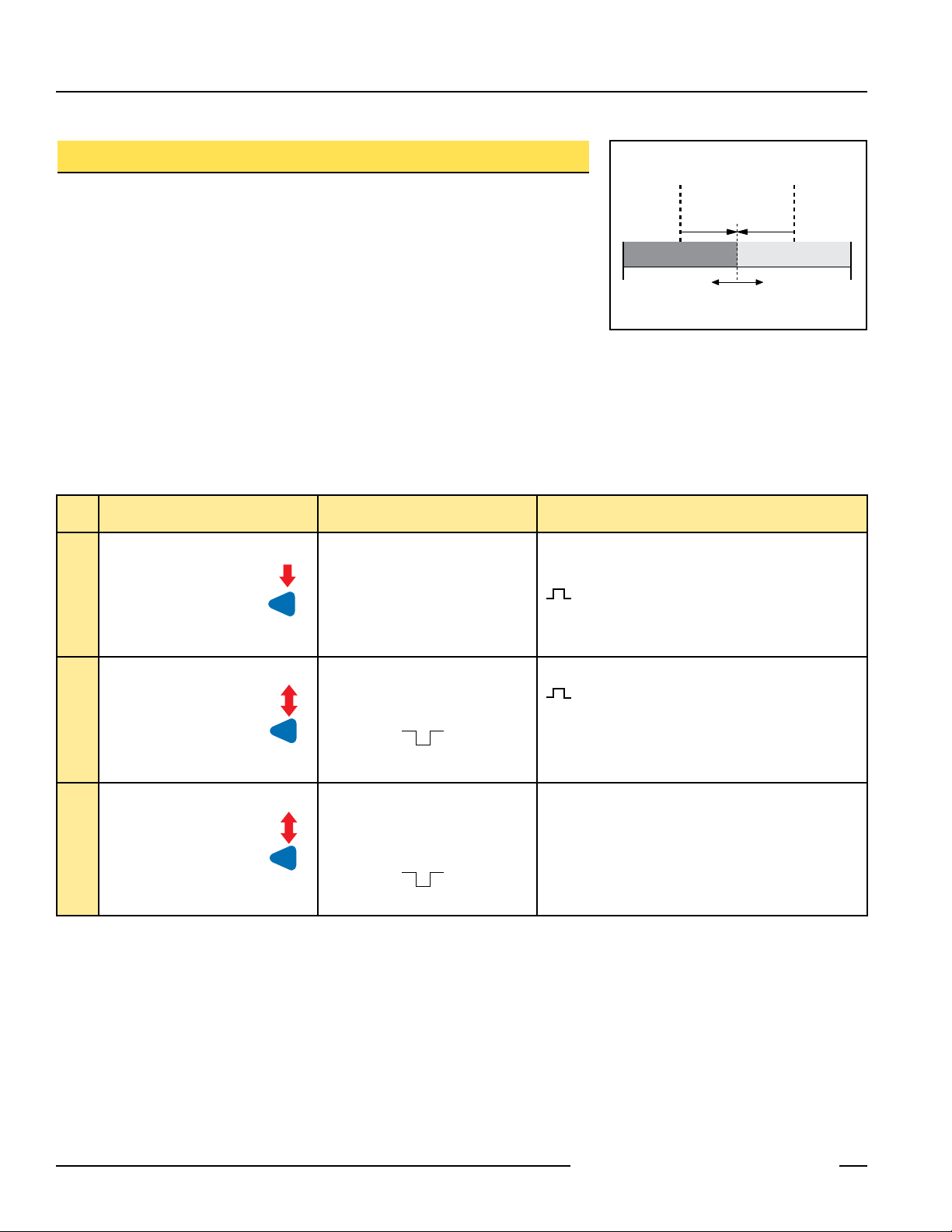
SETUP Mode
SETUP mode is used to configure discrete sensor output response for:
• Light or Dark operate
• 20- or 40-millisecond pulse stretcher (OFF-delay), if required.
It will be necessary to access SETUP mode only if the settings that result from
TEACH mode are not the settings required for the application. The status LEDs indicate
the output response configuration when the sensor is in RUN mode (see table below).
To change the output response settings;
1. Press and hold both push buttons for at least two seconds (or double-pulse the
remote line), until the signal strength light bar turns OFF.
2. Click either push button (or pulse the remote line) to toggle through the six possible
settings, indicated as follows:
Output Configuration
Delay
Indicator
LO
Indicator
DO
Indicator
Light operate with no delay OFF ON OFF
Light operate with 20 ms delay Flashing ON OFF
Light operate with 40 ms delay ON ON OFF
Dark operate with no delay OFF OFF ON
Dark operate with 20 ms delay Flashing OFF ON
Dark operate with 40 ms delay ON OFF ON
3. Press and hold both push buttons (or hold the remote line) until the signal strength
light bar turns ON, indicating return to RUN mode.
NOTE: If SETUP mode configuration is interrupted and remains inactive for 30 seconds,
the sensor returns to RUN mode with the most recent settings (i.e., exits and
saves current selection).
Locking Out (Disabling) the Push Buttons
In addition to its configuration function, the remote input may be used to disable the push
buttons for security. Disabling the push buttons prevents undesired tampering with the
configuration settings. Connect the gray wire of the sensor as described on page 3, and
four-pulse to either enable or disable the push buttons:
P/N 59574 rev. B 7
Banner Engineering Corp. • Minneapolis, MN U.S.A.
www.bannerengineering.com • Tel: 763.544.3164
NOTE: Push buttons can be disabled/enabled from the remote line only.
Page 8

R55 Expert™ Color Mark Sensors
90º
Roller or
Tension Bar
Opaque,
Non-reflective
Web Material
Focus Distance
10.0 mm (0.39")
R55E
Mount the R55E perpendicular to
non-reflective (matte) materials
Approximately 15º
Focus Distance
10.0 mm (0.39")
Mount the R55E at approximately 15°
from perpendicular to transparent
and opaque reflective materials
Roller or
Tension Bar
Transparent or
Opaque Reflective
Web Material
R55E
Lens
Cap
10 ± 3 mm
Cap
Surface of
Material
Lens
10 ± 3 mm
Installation Notes
Lens Location
The lens of the R55E may be installed at either of two lens ports (see Figure 6). The lens
and the lens port cap are both threaded and may be exchanged by hand; no tools are
required. The lens and cap both include an o-ring seal.
NOTE: Lens port cap must be installed for reliable operation.
Mounting the Sensor
The R55E includes a total of eight M5 threaded holes used for mounting (see dimension
drawing on page 10). These threaded holes are positioned to match the mounting hole
patterns common to other color mark sensors. The R55E includes four
M5 x 0.8 x 6 mm stainless steel cap screws and a hex key wrench.
The R55E focus is located at 10 mm (0.39") ahead of the lens surface. The R55E must
be mounted within 3 mm (0.12") of this distance from the surface of the material for
reliable sensing (Figure 7).
Mounting Considerations
1. Whenever possible, it is a good idea to sense a web material at a location where it
passes over a tension bar or roller, to minimize the adverse effects of web “flutter” or
sag (Figure 7).
2. When sensing a color mark on a reflective (shiny) material, mount the R55E at
an angle that places the lens centerline at approximately 15° off perpendicular to
the material’s surface (see Figure 8). This “skew angle” will minimize strong direct
reflections (which tend to overwhelm the sensor), and allow the sensor to discern the
relatively small optical contrast offered by difference in colors.
3. Clear materials are poor reflectors of light. When sensing a mark printed on a clear
material (e.g., a clear poly web), position a reflective surface directly behind the clear
material that will return light to the R55E. The printed mark, regardless of its color,
then becomes the dark condition, as it blocks the light from reaching the reflective
surface. Most clear materials are also shiny; it is important also to include a 15° skew
angle when sensing clear materials (Figure 8).
Figure 6. R55E Lens Positions
Figure 7. Mounting for sensing opaque
non-reflective materials
8 P/N 59574 rev. B
Figure 8. Mounting for sensing opaque
reflective and transparent
materials
Banner Engineering Corp. • Minneapolis, MN U.S.A.
www.bannerengineering.com • Tel: 763.544.3164
Page 9

R55 Expert™ Color Mark Sensors
Specifications
Supply Input 10 to 30V dc (10% maximum ripple) at less than 80 mA, exclusive of load.
Supply Protection Circuitry Protected against reverse polarity and transient voltages.
Output Configuration Digital outputs: Bipolar. One current sourcing (PNP) and one current sinking (NPN) open-collector transistor
Analog output: Current source proportional to the received light level, updated in real time (every 50 microseconds)
Output Rating Digital outputs are 100 mA maximum (each)
Off-state leakage current < 10 microamps at 30V dc
Saturation voltage (NPN output) < 1.5V at 150 mA dc
Saturation voltage (PNP output) < 2.0V at 150 mA dc
Current Sourcing Analog output: 0 to 10 mA
Maximum load voltage drop is ≤ 2 volts
Output Protection Protected against false pulse on power-up and continuous overload or short-circuit of outputs.
Output Response 50 microseconds NOTE: 1 second delay on power-up; outputs do not conduct during this time.
Adjustments
(see pages 3–7)
Indicator LEDs 10-segment (green) light bar indicates signal strength
Construction Zinc alloy die-cast and steel housing with black acrylic polyurethane finish
Environmental Rating IEC IP67; NEMA 6
Connections PVC-jacketed 6-conductor 2 m (6.5') or 9 m (30') attached cable with internal strain relief, or 6-pin Euro-style
Operating Conditions Temperature: -10° to +55° C (+14° to 131° F)
Vibration and
Mechanical Shock
Application Notes • Do not mount the sensor directly perpendicular to shiny surfaces; position it at approximately a 15° angle in
Using push buttons (“+” Dynamic and “-” Static):
Manually adjust discrete output switchpoint using “+” or “-” buttons
Dynamic TEACH (teach on-the-fly) sensitivity adjustment
Static TEACH sensitivity adjustment
Light operate/Dark operate
OFF-delay select: 0 milliseconds, 20 milliseconds or 40 milliseconds
Using Remote TEACH input (gray wire):
Dynamic TEACH (teach on-the-fly) sensitivity adjustment
Static TEACH sensitivity adjustment
Light operate/Dark operate
OFF-delay select: 0 milliseconds, 20 milliseconds or 40 milliseconds
Lockout of push buttons for security
Light Operate: green
Dark Operate: green
Outputs Conducting: yellow
OFF-Delay (green): SETUP Mode RUN Mode
OFF — no delay OFF — no delay
Flashing — 20 ms delay ON — 20 or 40 ms Delay
ON — 40 ms delay
Lens and lens port cap are o-ring sealed
Lens is acrylic
Lens port cap and lens holder are ABS
quick-disconnect. Mating QD cables are purchased separately. See Cables, page 10.
Maximum Relative Humidity: 90% at 50° C (non-condensing)
All models meet IEC 68-2-6 and IEC 68-2-27 testing criteria.
relation to the sensing target (see page 8).
• Minimize web or product “flutter” whenever possible to maximize sensing reliability.
• The analog output is proportional to the received light signal. The analog output is unaffected by + or
– manual sensitivity adjustments.
Banner Engineering Corp. • Minneapolis, MN U.S.A.
P/N 59574 rev. B 9
www.bannerengineering.com • Tel: 763.544.3164
Page 10

R55 Expert™ Color Mark Sensors
SETUP
DOLOOFF
Delay
Switch Point
+
DYNAMIC
–
STATIC
21.0 mm
(0.83")
30.0 mm
(1.18")
30.4 mm
(1.20")
5.0 mm
(0.20")
3.0 mm (0.12")
15.0 mm
(0.59")
80.0 mm
(3.15")
43.0 mm
(1.69")
15.0 mm (0.59")
28.0 mm
(1.10")
M5 x 0.8 Thread
x 6.3 mm Deep (8 Holes),
max. torque 45 in./lbs.
25 mm
(1.0")
39.0 mm
(1.54")
28.0 mm
(1.10")
55.5 mm
(2.19")
15 mm
(0.59")
3 mm (0.12")
18.0 mm
(0.71")
bn
wh
bu
+
–
bk
pk
Load
0-10mA
Load
10-30V dc
Remote Input
gy
bn
wh
bu
+
–
bk
Load
Load
10-30V dc
Remote Input
gy
pk
0-10mA
38 mm max.
(1.5")
M12 x 1
ø 15 mm
(0.6")
38 mm max.
(1.5")
M12 x 1
ø 15 mm
(0.6")
44 mm max.
(1.7")
White Wire
Blue Wire
Pink Wire
Black Wire
Gray Wire
Brown Wire
Dimensions
Euro-style QD Models
Style Model Length Dimensions Pinout
6-Pin
Euro-Style
Straight
6-Pin
Euro-Style
Right-Angle
10 P/N 59574 rev. B
MQDC-606
MQDC-615
MQDC-630
MQDC-606RA
MQDC-615RA
MQDC-630RA
Cabled Models
Quick-Disconnect (QD) Cables
2 m (6.5')
5 m (15')
9 m (30')
2 m (6.5')
5 m (15')
9 m (30')
Hookups
Quick-Disconnect Models
Banner Engineering Corp. • Minneapolis, MN U.S.A.
www.bannerengineering.com • Tel: 763.544.3164
Page 11

R55 Expert™ Color Mark Sensors
15.0°
50.8 mm
(2.00")
31.8 mm
(1.25")
8 x R 3.3 mm
(0.13")
12.7 mm
(0.50")
15.2 mm
(0.60")
11.4 mm
(0.45")
13.3 mm
(0.53")
24.1 mm
(0.95")
12 x R 2.6 mm
(0.10")
2.6 mm
(0.10")
2 x 12.4 mm
(0.49")
24.8 mm
(0.98")
27.9 mm
(1.10")
C
L
2 x 5.6 mm
(0.22")
2 x 7.6 mm
(0.30")
5.4 mm
(0.21")
50.8 mm
(2.00")
25.4mm
(1.00")
4 x R 6.4 mm
(0.25")
2 x 12.4 mm
(0.49")
24.8 mm
(0.98")
27.9 mm
(1.10")
C
L
2 x 5.6 mm
(0.22")
2 x 7.6 mm
(0.30")
8 x R 3.3 mm
(0.13")
12.7 mm
(0.50")
15.2 mm
(0.60")
11.4 mm
(0.45")
13.3 mm
(0.53")
24.1 mm
(0.95")
12 X R 2.6 mm
(0.10")
5.4 mm
(0.21")
50.8 mm
(2.00")
25.4mm
(1.00")
2.6 mm
(0.10")
82.6 mm
(3.25")
4 x R 6.4 mm
(0.25")
8 x R 3.3 mm
(0.13")
12.7 mm
(0.50")
15.2 mm
(0.60")
11.4 mm
(0.45")
13.3 mm
(0.53")
24.1 mm
(0.95")
2.6 mm
(0.10")
2 x 12.4 mm
(0.49")
27.9 mm
(1.10")
C
L
2 x 5.6 mm
(0.22")
2 x 7.6 mm
(0.30")
12 X R 2.6 mm
(0.10")
5.4 mm
(0.21")
50.8 mm
(2.00")
25.4mm
(1.00")
24.8 mm
(0.98")
4 x R6.4 mm
(0.25")
4x R6.4 mm (0.25")
4x R2.6
(0.10")
28.0 mm
(1.10")
8.2 mm
(0.32")
7.9 mm
(0.31")
3.8 mm
(0.15")
44.5 mm
(1.75")
15.0°
34.3 mm
(1.35")
25.4 mm
(1.00")
2.6 mm
(0.10")
8x R3.3 mm (0.13")
2x 10.2 mm
(0.40")
7.1 mm
(0.28")
8.1 mm
(0.32")
30.5 mm
(1.20")
10.2 mm
(0.40")
Accessory Mounting Brackets
SMB55A
SMB55RA
• 15° offset bracket
• 12-gauge stainless steel
• Right-angle bracket
• 12-gauge stainless steel
shown
with R58
sensor
shown
with R58
sensor
SMB55F
shown
with R58
sensor
SMB55S
• Flat mount bracket
• 12-gauge stainless steel
• 15° offset bracket
• 12-gauge stainless steel
shown
with R58
sensor
Replacement Lens
P/N 59574 rev. B 11
Models Description
UC-R55 Replacement lens for R55E
Banner Engineering Corp. • Minneapolis, MN U.S.A.
www.bannerengineering.com • Tel: 763.544.3164
Page 12

R55 Expert™ Color Mark Sensors
WARNING . . . Not To Be Used for Personnel Protection
Never use these products as sensing devices for personnel protection. Doing so could lead to serious injury or death.
These sensors do NOT include the self-checking redundant circuitry necessary to allow their use in personnel safety applications. A sensor failure
or malfunction can cause either an energized or de-energized sensor output condition. Consult your current Banner Safety Products catalog for
safety products which meet OSHA, ANSI and IEC standards for personnel protection.
WARRANTY: Banner Engineering Corp. warrants its products to be free from defects for one year. Banner Engineering Corp. will repair or replace,
free of charge, any product of its manufacture found to be defective at the time it is returned to the factory during the warranty period. This warranty
does not cover damage or liability for the improper application of Banner products. This warranty is in lieu of any other warranty either expressed or
implied.
P/N 59574 rev. B
Banner Engineering Corp., 9714 Tenth Ave. No., Minneapolis, MN USA 55441 • Phone: 763.544.3164 • www.bannerengineering.com • Email: sensors@bannerengineering.com
 Loading...