

Page 1
U-GAGE QT50ULB Series Sensors with
70137
Analog Output
Datasheet
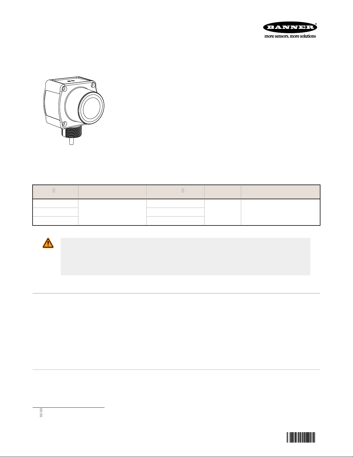
Long-range ultrasonic sensors with TEACH-mode programming
• Fast, easy-to-use TEACH-Mode programming; no potentiometer adjustments
• Scalable output automatically distributes the output signal over the width of the
programmed sensing window
• Minimum and Maximum window limits can be adjusted independently
• Selectable 0 to 10 V dc or 4 to 20 mA output, selected via DIP switch
• Access to bank of 8 DIP switches through sealed cover for superior user
functionality
• Rugged encapsulated design for harsh environments
• Unique housing design allows for multiple mounting configurations
• Choose models with integral 2 m (6.5 ft) or 9 m (30 ft), or with Mini-style or
Euro-style quick-disconnect fitting
• Wide operating range of –20 °C to 70 °C (–4 °F to 158 °F)
• Temperature compensation
• Programmable for either positive or negative output slope
Models
QT50ULB
QT50ULBQ 5-pin Mini-style QD
QT50ULBQ6 5-pin Euro-style QD
1
WARNING: Not To Be Used for Personnel Protection
Never use this device as a sensing device for personnel protection. Doing so could lead to
serious injury or death. This device does not include the self-checking redundant circuitry necessary
to allow its use in personnel safety applications. A sensor failure or malfunction can cause either an
energized or de-energized sensor output condition.
Sensing Range Cable
5-wire, 2 m (6.5 ft) cable
200 mm to 8 m (8 inches to
26 feet)
2
Supply
Voltage
10 to 30 V dc
Output
Selectable: 0 to 10 V dc or 4 to 20
mA
Principles of Operation
Ultrasonic sensors emit one or multiple pulses of ultrasonic energy, which travel through the air at the speed of sound. A
portion of this energy reflects off the target and travels back to the sensor. The sensor measures the total time required
for the energy to reach the target and return to the sensor. The distance to the object is then calculated using the
following formula: D = ct ÷ 2
D = distance from the sensor to the target
c = speed of sound in air
t = transit time for the ultrasonic pulse
To improve accuracy, an ultrasonic sensor may average the results of several pulses before outputting a new value.
Temperature Effects
The speed of sound is dependent upon the composition, pressure and temperature of the gas in which it is traveling. For
most ultrasonic applications, the composition and pressure of the gas are relatively fixed, while the temperature may
fluctuate.
In air, the speed of sound varies with temperature according to the following approximation:
1
Information about discrete-output models is available on Banner’s website: www.bannerengineering.com.
2
To order the 9 m cable models, add the suffix “w/30” to the model number of a cabled sensor (e.g., QT50ULB w/30). Models with
a QD connector require a mating cable.
Original Document
70137 Rev. B
4 April 2014
Page 2
C
m/s
= 20 √
273 + T
C
ft/s
=
49 √460 + T
F
C
Current-Sourcing Models
Target Position
Positive
Slope
Near
Window
Far
Window
Analog Output (mA)
20
4
Negative
Slope
Voltage-Sourcing Models
Target Position
Positive
Slope
Near
Window
Far
Window
Voltage Output (V dc)
10
0
Negative
Slope
3
ON
DIP
1 2 3 4 5 6 7 8
ON
DIP
1 2 3 4 5 6 7 8
ON
DIP
ON Position
U-GAGE QT50ULB Series Sensors with Analog Output
In metric
In English units:
units:
C
= speed of sound in meters per second C
m/s
= speed of sound in feet per second
ft/s
TC = temperature in °C TF = temperature in °F
The speed of sound changes roughly 1% per 6° C (10° F). QT50U series ultrasonic sensors have temperature
compensation available, via the 8-pin DIP switch. Temperature compensation will reduce the error due to temperature by
about 90%.
NOTE: NOTE: If the sensor is measuring across a temperature gradient, the compensation will be less
effective.
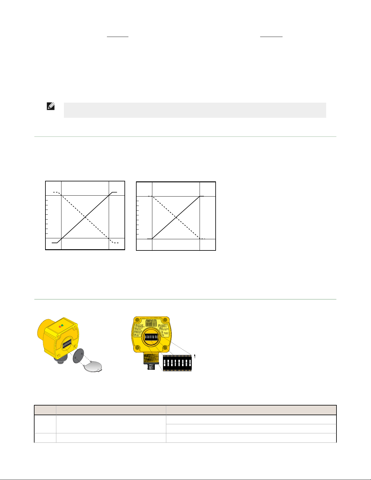
Analog Output Slope
The U-GAGE QT50ULB Sensor may be programmed for either a positive or a negative output slope, depending on which
conditions are taught for the Min and Max Analog limits. If the Min Analog limit is the Near Window setting and the Max
Analog limit is the Far Window setting, then the slope will be positive. If the opposite is true, then the slope will be
negative.
Figure 1. Positive and Negative Output Slops
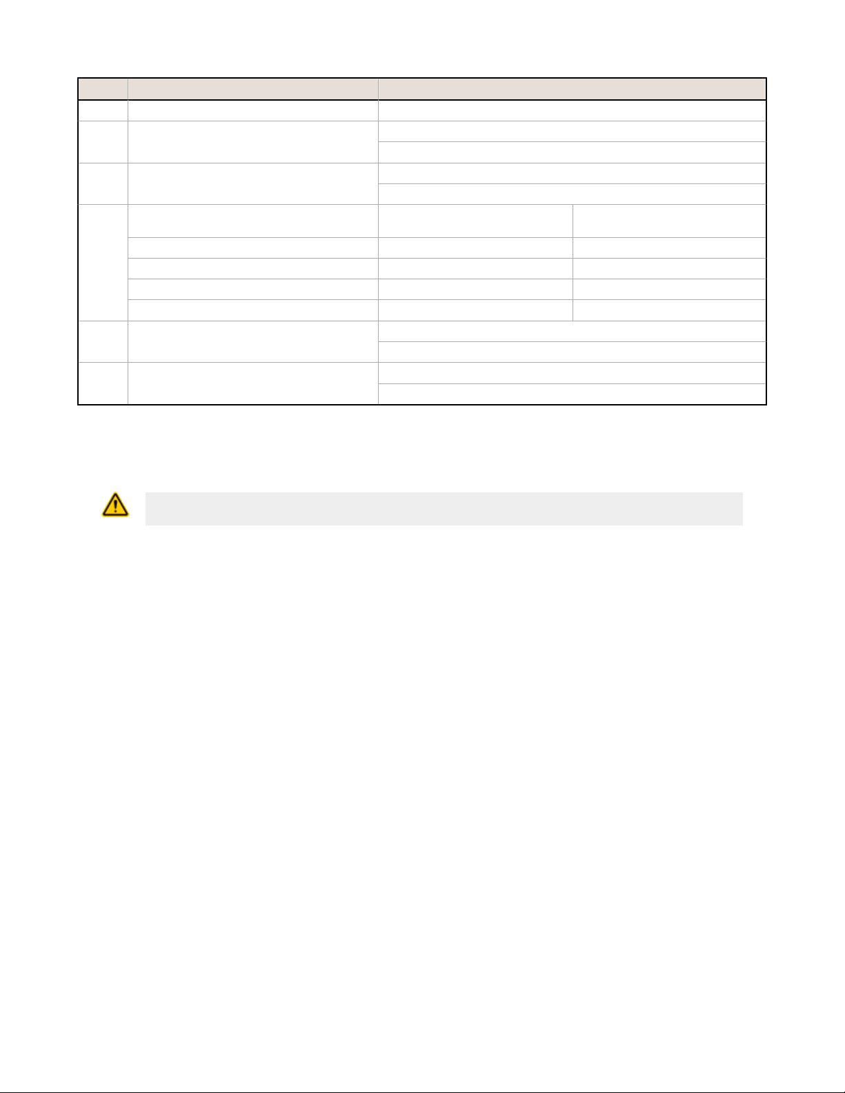
Configuration
The U-GAGE QT50ULB Sensor features an
8-pin DIP switch bank for user setup. The
DIP switches are located behind the access
cover on the back of the sensor as shown. A
spanner tool is included with each sensor
for removing the cover.
Figure 2. Removing the Access Cover
Switch Function Settings
1 Voltage/Current Mode ON = Current mode: 4 to 20 mA
2 Loss of Echo ON* = Min-Max Mode
2 www.bannerengineering.com - tel: 763-544-3164 P/N 70137 Rev. B
Figure 3. DIP Switch Location
OFF* = Voltage mode: 0 to 10 V dc
Page 3
U-GAGE QT50ULB Series Sensors with Analog Output
Switch Function Settings
OFF = Hold Mode
3 Min-Max ON = Default to maximum output value on loss of echo
OFF* = Default to minimum output value on loss of echo
4 Teach/Enable Control ON* = Configured for remote teach
OFF = Configured for enable
5 and 6 Analog Voltage Output Response for 95%
of Step Change
100 ms with 100 ms update OFF OFF
500 ms with 100 ms update* ON* OFF*
1100 ms with 100 ms update OFF ON
2300 ms with 100 ms update ON ON
7 Temperature Compensation ON* = Enabled
8 Factory Calibration ON = For factory calibration only; switch should be set to OFF for use
Switch 5 Switch 6
OFF = Disabled
OFF* = DIP-switch settings in control
* Factory default setting
DIP Switch Selectable Functions
CAUTION: To avoid damage to the sensor caused by static discharge (ESD), observe proper ESD
precautions (grounding) while adjusting the DIP switches.
Switch 1: Output Mode Select
ON = 4 to 20 mA current output is enabled
OFF = 0 to 10 V dc voltage output is enabled
Switch 1 configures the sensor internally to use either the current output or voltage output configuration.
Switch 2: Loss of Echo Mode Select
ON = Min-Max Mode
OFF = Hold Mode
Switch 2 determines the output response to the loss of echo. “Min-Max Mode” (Switch 2 ON) drives the output to either
the minimum value or the maximum value when the echo is lost. (Minimum or Maximum value is selected via Switch 3.)
“Hold Mode” (Switch 2 OFF) maintains the output at the value which was present at the time of echo loss.
Switch 3: Min-Max Default
ON = Default to maximum output value at loss of echo (10.5 V dc or 20.8 mA)
OFF = Default to minimum output value at loss of echo (0 V dc or 3.6 mA)
Switch 3 selects the output response to loss of echo when “Min-Max Mode” is selected via Switch 2. When Switch 2 is OFF,
Switch 3 has no function.
Switch 4: Teach/Transmit Enable Control
ON = Gray (or yellow) wire configured for remote teach
OFF = Gray (or yellow) wire configured for transmit enable/disable: High (5 to 30 V dc) - Transmit Enabled (Power LED
solid Green); Low (0 to 2 V dc) - Transmit Disabled (Power LED flashes at 2 Hz)
When Switch 4 is ON, the gray wire is used to teach window limits to the sensors.
When Switch 4 is OFF, the gray wire is used to enable and disable the sensor’s transmit burst. The sensor output will react
as if a “loss of echo” occurred and either hold the output or change to minimum or maximum value (depending on switch 2
and 3 settings). This function may be used when multiple sensors are in close proximity, which may make them vulnerable
to crosstalk interference. A PLC can be used to enable the sensors one at a time to avoid crosstalk.
Switches 5 and 6: Response Speed Adjustment
P/N 70137 Rev. B www.bannerengineering.com - tel: 763-544-3164 3
Page 4

U-GAGE
MIN
SIGNAL
TM
MAX
POWER
ANALOG
WINDOW
LIMIT
MIN
ANALOG
MAX
U-GAGE QT50ULB Series Sensors with Analog Output
Switches 5 and 6 are used to set the speed of the output response. The four values for response speed relate to the
number of sensing cycles over which the output value is averaged.
Switch 7: Temperature Compensation
ON = Temperature compensation enabled
OFF = Temperature compensation disabled
Changes in air temperature affect the speed of sound, which in turn affects the distance reading measured by the sensor.
An increase in air temperature shifts both sensing window limits closer to the sensor. Conversely, a decrease in air
temperature shifts both limits farther away from the sensor. This shift is approximately 3.5% of the limit distance for a 20
°C change in temperature. With temperature compensation enabled (Switch 7 ON), the sensor will maintain the window
limits to within 1.8 percent over the –20 °C to 70 °C range.
The temperature sensor in the sensor’s bezel cannot adapt to temperature change as quickly as an external temperature
device can. When there are fast fluctuations in temperature, it may be best to use an external temperature monitor and
feed its signal and the uncompensated distance measurement into a controller and perform the compensation calculations
within the controller.
Consult the factory for details on performing temperature compensation calculations.
• If temperature compensation is enabled, exposure to direct sunlight can affect the sensor’s ability to accurately
compensate for changes in temperature.
• With temperature compensation enabled, the temperature warmup drift upon power-up is less than 0.8% of the
sensing distance. After 15 minutes, the apparent distance will be within 0.5% of the actual distance. After 30
minutes, the apparent distance will be within 0.3% of the actual distance.
Switch 8: Factory Calibration
ON = Factory calibration only
OFF = Normal operation
MIN - Minimum limit indicator
MAX - Maximum limit indicator
POWER - Sensor power indicator
SIGNAL - Target signal strength indicator
Figure 4. Sensor Features
General Notes on Programming
• The sensor returns to RUN mode if the limit is not registered within 120 seconds after entering TEACH Mode.
• Press and hold the programming push button for more than 2 seconds (before teaching the limit) to exit PROGRAM
mode without saving any changes. The sensor will revert to the last saved program.
• If the push buttons do not respond, perform a remote lockout procedure to enable push buttons.
Sensor Programming
Two TEACH methods may be used to program the sensor:
• Teach individual minimum and maximum limits
• Use the Auto-Window feature to center a sensing window around the taught position
The sensor may be programmed either via its two push buttons, or via a remote switch. Remote programming also may be
used to disable the push buttons, preventing unauthorized personnel from adjusting the programming settings. To access
this feature, connect the gray wire of the sensor to 0–2 V dc, with a remote programming switch between the sensor and
the voltage.
NOTE: The impedance of the Remote Teach input is 12 kΩ.
Programming is accomplished by following the sequence of input pulses. The duration of each pulse (corresponding to a
push button “click”), and the period between multiple pulses, are defined as “T” where 0.04 seconds < T < 0.8 seconds.
4 www.bannerengineering.com - tel: 763-544-3164 P/N 70137 Rev. B
Page 5

T
T T
T
U-GAGE QT50ULB Series Sensors with Analog Output
Teaching Minimum and Maximum Limits
The Min and Max Analog limits are independent. To readjust either limit, it is necessary to follow the teach procedure for
that limit only.
Setting the Minimum Analog Limit
Push Button Method
Step Action Result
1 Push and hold the Min Analog button Min Analog LED turns ON red; sensor is waiting for 0 V dc or 4
2 Position the target for the Min Analog limit Sensor learns Min limit
3 “Click” the Min Analog button Min LED changes from red to amber or flashing amber
Remote Line Method (0.04 s < T < 0.8 s)
Step Action Result
1 Position the target for the Min Analog limit Sensor learns the 0 V dc or 4 mA limit
2
Single-pulse the remote line
mA limit.
Min Analog LED flashes red once
Setting the Maximum Analog Limit
Push Button Method
Step Action Result
1 Push and hold the Max Analog button Max Analog LED turns ON red; sensor is waiting for 10 V dc or
2 Position the target for the Max Analog limit Sensor learns Max limit
3 “Click” the Max Analog button Max LED changes from red to amber or flashing amber
Remote Line Method (0.04 s < T < 0.8 s)
Step Action Result
1 Position the target for the Max Analog limit Sensor learns the 10 V dc or 20 mA limit
2
Double-pulse the remote line
20 mA limit.
Max Analog LED flashes red once
Teaching Limits Using the Auto-Window Feature
Teaches a sensing distance threshold centered within a fixed sensing window (a 1 m window centered on the position
taught). This procedure centers the analog output on the taught position at approximately 5 V dc or 12 mA.
Setting the Minimum Analog Limit
Push Button Method
Step Action Result
1 Push and hold the Min Analog button Min Analog LED turns ON red
2 “Click” the Max Analog button Max Analog LED turns ON red (both the Min and Max Analog
LEDs should now be ON)
P/N 70137 Rev. B www.bannerengineering.com - tel: 763-544-3164 5
Page 6

T TTT
T
T TTT
T
T T
T T T
T T
U-GAGE QT50ULB Series Sensors with Analog Output
Remote Line Method (0.04 s < T < 0.8 s)
Step Action Result
1 Position the target at the location where the midpoint of the
window should be.
2
Triple-pulse the remote line
Min and Max LEDs both flash red (0.5 second), then turn
amber
Setting the Maximum Analog Limit
Push Button Method
Step Action Result
1 Position the target at the location where the midpoint of the
window should be.
2 “Click” either push button
3 “Click” the other push button The Red Teach LEDs change to amber and the sensor returns
Remote Line Method (0.04 s < T < 0.8 s)
Step Action Result
1 Position the target at the location where the midpoint of the
window should be.
2
Its LED flashes red
to RUN mode
Min and Max LEDs both flash red (0.5 second), then turn
amber
Triple-pulse the remote line
Push Button Lockout
Enables or disables the keypad to prevent unauthorized personnel from adjusting the programming settings.
Push Button
Procedure Result
Not available via push button Not applicable
Remote Line
Procedure
0.04 sec. < T < 0.8 sec.
Four-pulse the remote line
Result
Push buttons are either enabled or
disabled, depending on previous
condition.
6 www.bannerengineering.com - tel: 763-544-3164 P/N 70137 Rev. B
Page 7

Min
Max
Min
Power Signal Power Signal Power Signal Power Signal
Max
Min
Max
Min
Max
Minimum
Operating
Range
Minimum
Analog
Setpoint
Maximum
Analog
Setpoint
Maximum
Operating
Range
Target Within
Limits
Target Outside
Min Limit
Target Outside
Sensing Range
Target Outside
Max Limit
Target
Target
Target
Target
U-GAGE QT50ULB Series Sensors with Analog Output
Status Indicators
Figure 5. Status Indicator Conditions for Each Target Position
Signal LED (Red) – indicates the strength and condition of the sensor’s incoming signal.
Signal LED Status Indicates
ON Bright Good signal
ON Dim Marginal signal strength
OFF No signal is received or the target is beyond the sensor’s range limitations
Output LEDs (Amber) – indicate the position of the target relative to the window limits.
Output/Teach LED Indicates
ON Red (either) In Teach mode; waiting for limits to be taught
Min Analog ON Amber
Target is within analog window limits
Max Analog ON Amber
Min Analog ON Amber
Target is outside max. window limit
Max Analog Flashing Amber
Min Analog Flashing Amber
Target is outside Min window limit
Max Analog ON Amber
Min Analog OFF
No signal condition or Outside operating limits
Max Analog OFF
Power ON/OFF LED (Green) – indicates the operating status of the sensor.
Power ON/OFF LED Indicates
OFF Power is OFF
Flashing at 2 Hz Transmit disabled (see DIP switch settings)
ON Solid Sensor is operating normally
P/N 70137 Rev. B www.bannerengineering.com - tel: 763-544-3164 7
Page 8

−
4
5
1
3
2
10–30 V dc
Remote Teach
0–2 V dc
4–20 mA or
0–10 V dc
Shield
+
Shield
4
5
1
3
2
10–30 V dc
Remote Teach
0–2 V dc
4–20 mA or
0–10 V dc
+
−
4
5
1
3
2
10−30 V dc
Remote Teach
0–2 V dc
4–20 mA or
0–10 V dc
+
Shield
−
67.4 mm
[2.66”]
38.1 mm
[1.5”]
18 mm
[0.71”]
66 mm
[2.6”]
84.2 mm
[3.32”]
33 mm
[1.3”]
Temperature
Sensor Location
Internal thread 1/2” NPSM
External thread M30 x 1.5
37 mm
[1.46”]
4x 4.4 mm dia
[0.17” dia]
50.8 mm
[2”]
50.8 mm
[2”]
34.2 mm
[1.35”]
34.2 mm
[1.35”]
U-GAGE QT50ULB Series Sensors with Analog Output
Wiring
Integral Cable Model Quick-Disconnect Model (5-pin
Mini-style)
1 = brown
2 = white
3 = blue
4 = black
5 = gray
1 = brown
2 = white
3 = blue
4 = black
5 = yellow
Banner recommends connecting the shield wire to earth ground or dc common.
Dimensions
Cabled Models
5-pin Mini-style Models
Quick-Disconnect Model (5-pin
Euro-style)
1 = brown
2 = white
3 = blue
4 = black
5 = gray
5-pin Euro-style
Models
8 www.bannerengineering.com - tel: 763-544-3164 P/N 70137 Rev. B
Page 9

Effective Beam Width
Target Distance
-200 mm
-400 mm
-600 mm
200 mm
400 mm
0
600 mm
800 mm
1000 mm
-800 mm
-1000 mm
0 1 m
(3.3')
2 m
(6.6')
3 m
(9.8')
4 m
(13.1')
5 m
(16.4')
6 m
(19.6')
7 m
(22.9')
8 m
(26.2')
8"
-8"
0
16"
-16"
24"
-24"
31"
-31"
-40"
40"
25 mm Rod
500 mm Plate
-10
-20
-30
10
0
20
30
40
-40
0
Target Distance (m)
Target Rotation (deg)
1 m
(3.3’)
2 m
(6.6’)
3 m
(9.8’)
4 m
(13.1’)
5 m
(16.4’)
6 m
(19.6’)
7 m
(22.9’)
8 m
(26.2’)
U-GAGE QT50ULB Series Sensors with Analog Output
Specifications
Supply Voltage and Current
10 to 30 V dc (10% maximum ripple)
100 mA max at 10 V, 40 mA max at 30 V (exclusive of load)
Sensing Range
200 mm to 8 m (8 inches to 26 feet)
Ultrasonic Frequency
75 kHz burst, rep. rate 96 ms
Supply Protection Circuitry
Protected against reverse polarity and transient overvoltages
Output Protection
Protected against short circuit conditions
Delay at Power-up
1.5 seconds
Analog Output Configuration (Voltage Sourcing: 0 to 10 V dc)
Minimum Load Resistance = 500 ohms
Minimum Required Supply Voltage for Full 0-10 V Output Span =
(1000/RLoad + 13) V dc
Analog Output Configuration (Current Sourcing: 4 to 20 mA)
Maximum Load Resistance = 1 kΩ or ( Vsupply/0.02 - 5) ohms,
whichever is lower
Minimum required supply voltage for full 4-20 mA output span = 10 V
dc or [(RLoad × 0.02) + 5] V dc, whichever is greater.
4 to 20 mA output calibrated at 25 °C with a 250 Ω load.
Temperature Effect
Uncompensated: 0.2% of distance/°C
Compensated: 0.02% of distance/°C
Linearity
+/- 0.2% of span from 200 to 8000 mm
+/- 0.1% of span from 500 to 8000 mm (1 mm minimum)
Resolution
1.0 mm
Output Response Time
100 ms to 2300 ms
See DIP Switches 5 and 6
Minimum Window Size
20 mm
Adjustments
Sensing window limits: TEACH-Mode programming of near and far
window limits may be set using the push buttons or remotely via
TEACH input.
Indicators
Green Power On LED: Indicates power is ON
Red Signal LED: Indicates target is within sensing range, and the
condition of the received signal
Teach/Output indicator (bicolor Amber/Red): Amber – Target is within
taught limits; Flashing Amber – Target is outside taught window limits;
Red – Sensor is in TEACH mode
Remote TEACH
To Teach: Connect gray or yellow wire to 0 to 2 V dc; impedance 12 kΩ
Construction
Transducer: Ceramic/Epoxy composite
Housing: ABS/Polycarbonate
Membrane Switch: Polyester
Lightpipes: Acrylic
Operating Conditions
Temperature: –20 °C to 70 °C (–4 °F to 158 °F)
Maximum relative humidity: 100%
Connections
2 m (6.5 ft) or 9 m (30 ft) shielded 5-conductor (with drain) PVC
jacketed attached cable or 5-pin Euro-style quick-disconnect or 5-pin
Mini-style quick-disconnect
Environmental Rating
Leakproof design is rated IEC IP67; NEMA 6P
Vibration and Mechanical Shock
All models meet Mil Std. 202F requirements. Method 201A (vibration:
10 to 60Hz max., double amplitude 0.06", maximum acceleration 10G).
Also meets IEC 947-5-2 requirements: 30G 11 ms duration, half sine
wave
Temperature Warmup Drift
Less than 0.8% of sensing distance upon power-up with Temperature
Compensation enabled (see Temperature Compensation)
Application Notes
Objects passing inside the specified near limit (200 mm) may produce
a false response.
Certifications
Performance Curves
QT50U Effective Beam Pattern
P/N 70137 Rev. B www.bannerengineering.com - tel: 763-544-3164 9
QT50U (with 500 mm Plate) Maximum Target
Rotation Angle
Page 10

7/8-16UN-2B
ø 28 mm max.
(1.1")
61 mm max.
(2.4")
4
3
1
5
2
44 Typ.
ø 14.5
M12 x 1
2
3
4
1
5
32 Typ.
[1.26"]
30 Typ.
[1.18"]
ø 14.5 [0.57"]
M12 x 1
67
58
29
B
A
70
57
A
B
C
57
U-GAGE QT50ULB Series Sensors with Analog Output
Accessories
5-Pin Mini-Style Cordsets with Shield
Model Length Style Dimensions Pinout (Female)
MBCC2-506 1.83 m (6 ft)
MBCC2-515 4.57 m (15 ft)
Straight
MBCC2-530 9.14 m (30 ft)
5-Pin Threaded M12/Euro-Style Cordsets with Shield
Model Length Style Dimensions Pinout
MQDEC2-506 1.83 m (6 ft)
MQDEC2-515 4.57 m (15 ft)
MQDEC2-530 9.14 m (30 ft)
Straight
1 = Brown
2 = White
3 = Blue
4 = Black
5 = Yellow
MQDEC2-550 15.2 m (50 ft)
MQDEC2-506RA 1.83 m (6 ft)
MQDEC2-515RA 4.57 m (15 ft)
MQDEC2-530RA 9.14 m (30 ft)
MQDEC2-550RA 15.2 m (50 ft)
SMB30SC
• Swivel bracket with 30 mm
mounting hole for sensor
• Black reinforced
thermoplastic polyester
• Stainless steel mounting and
swivel locking hardware
included
Hole center spacing: A=ø 50.8
Hole size: A=ø 7.0, B=ø 30.0
Right-Angle
Brackets
SMB30MM
• 12-ga. stainless steel bracket
with curved mounting slots
for versatile orientation
• Clearance for M6 (¼ in)
hardware
• Mounting hole for 30 mm
sensor
Hole center spacing: A = 51, A to B = 25.4
Hole size: A = 42.6 x 7, B = ø 6.4, C = ø 30.1
1 = Brown
2 = White
3 = Blue
4 = Black
5 = Gray
Banner Engineering Corp Limited Warranty
Banner Engineering Corp. warrants its products to be free from defects in material and workmanship for one year following
the date of shipment. Banner Engineering Corp. will repair or replace, free of charge, any product of its manufacture
which, at the time it is returned to the factory, is found to have been defective during the warranty period. This warranty
does not cover damage or liability for misuse, abuse, or the improper application or installation of the Banner product.
THIS LIMITED WARRANTY IS EXCLUSIVE AND IN LIEU OF ALL OTHER WARRANTIES WHETHER EXPRESS OR
IMPLIED (INCLUDING, WITHOUT LIMITATION, ANY WARRANTY OF MERCHANTABILITY OR FITNESS FOR A
PARTICULAR PURPOSE), AND WHETHER ARISING UNDER COURSE OF PERFORMANCE, COURSE OF DEALING OR
TRADE USAGE.
10 www.bannerengineering.com - tel: 763-544-3164 P/N 70137 Rev. B
Page 11

U-GAGE QT50ULB Series Sensors with Analog Output
This Warranty is exclusive and limited to repair or, at the discretion of Banner Engineering Corp., replacement. IN NO
EVENT SHALL BANNER ENGINEERING CORP. BE LIABLE TO BUYER OR ANY OTHER PERSON OR ENTITY FOR
ANY EXTRA COSTS, EXPENSES, LOSSES, LOSS OF PROFITS, OR ANY INCIDENTAL, CONSEQUENTIAL OR
SPECIAL DAMAGES RESULTING FROM ANY PRODUCT DEFECT OR FROM THE USE OR INABILITY TO USE THE
PRODUCT, WHETHER ARISING IN CONTRACT OR WARRANTY, STATUTE, TORT, STRICT LIABILITY,
NEGLIGENCE, OR OTHERWISE.
Banner Engineering Corp. reserves the right to change, modify or improve the design of the product without assuming any
obligations or liabilities relating to any product previously manufactured by Banner Engineering Corp.
www.bannerengineering.com - tel: 763-544-3164
 Loading...