

Page 1
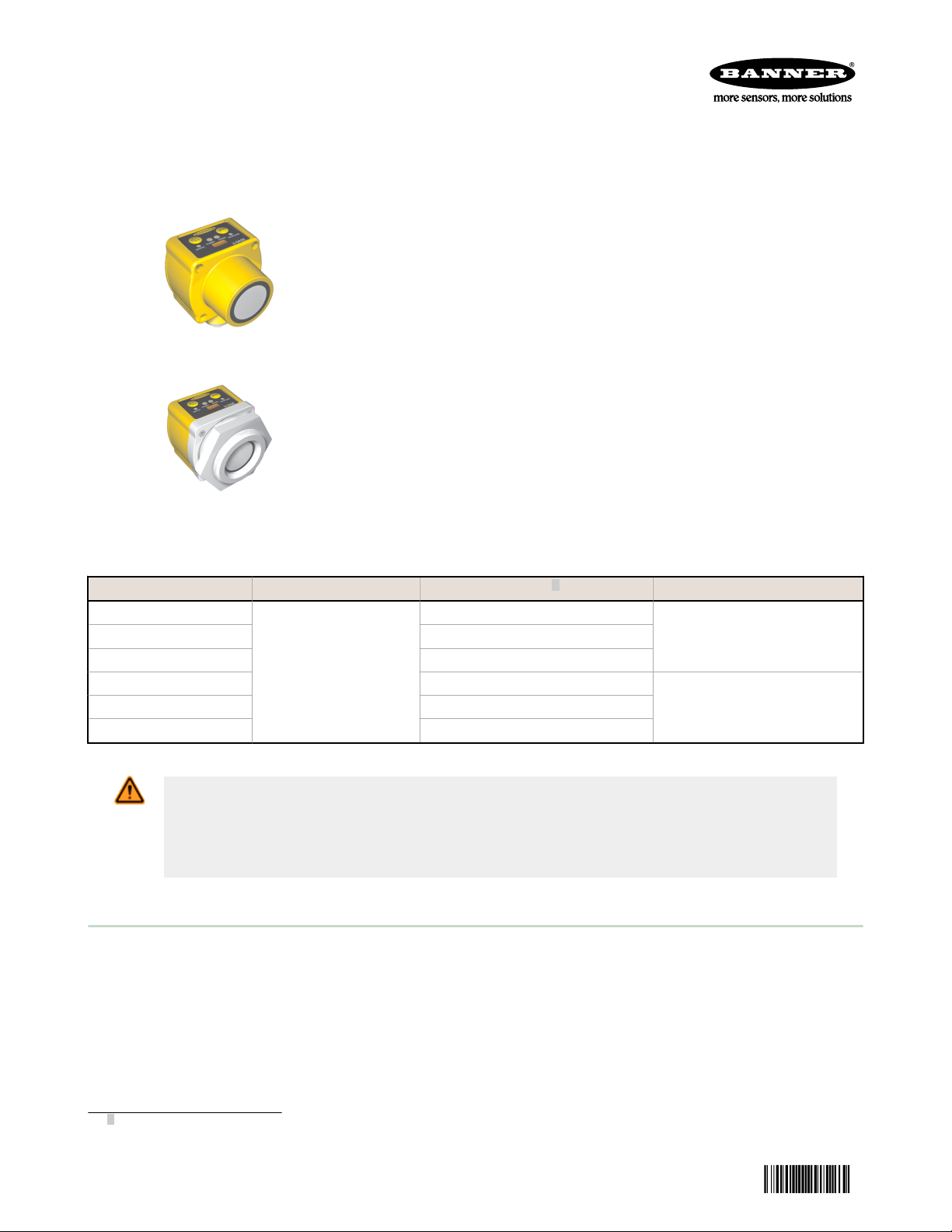
U-GAGE QT50UVR Series Sensors
117764
Datasheet
• Fast, easy-to-use TEACH-Mode programming; no potentiometer
adjustments
• SPDT electromechanical relay for high-capacity switching
• Universal supply voltage: 85 to 264 V ac / 48 to 250 V dc
• Rugged encapsulated design for harsh environments
• Models available with factory-installed Teflon® flange and film coating
bonded over the transducer for protection from harsh environments
• Unique housing design allows for multiple mounting configurations
• Choose models with integral 2 m (6.5 ft) or 9 m (30 ft) cable, or with
Figure 1. Standard Model
Teflon® is a registered trademark of Dupont
Information about dc-voltage models is available on Banner’s website:
www.bannerengineering.com
Figure 2. Teflon-Protected Model
Mini-style or Micro-style quick-disconnect fitting
• Wide operating range of –20 °C to 70 °C (–4 °F to 158 °F)
• Temperature compensation
™
Models Sensing Range Cable
QT50UVR3W
QT50UVR3WQ 5-pin Mini-style QD
QT50UVR3F 5-wire, 2 m (6.5 ft) cable
QT50UVR3FQ1 5-pin Micro-style QD
QT50UVR3FQ 5-pin Mini-style QD
200 mm to 8 m (8 inches
to 26 ft)
5-wire, 2 m (6.5 ft) cable
1
Operation Model
Window-limit (N.O.and N.C.)QT50UVR3WQ1 5-pin Micro-style QD
Fill-level control (pump-in and
pump out)
WARNING: Not To Be Used for Personnel Protection
Never use this device as a sensing device for personnel protection. Doing so could lead to
serious injury or death. This device does not include the self-checking redundant circuitry necessary
to allow its use in personnel safety applications. A sensor failure or malfunction can cause either an
energized or de-energized sensor output condition.
Overview
Ultrasonic sensors excel in position-monitoring applications and in applications involving clear or multi-colored targets.
QT50UVR sensors are available in a variety of models: dc sensors with either analog or two discrete outputs, or universal
voltage models that feature an SPDT electromechanical relay for switching larger loads. Programming and setup for the
universal voltage models are accomplished using the sensor’s two push buttons.
Models are available with Teflon sensor face and hex nut, plus Teflon-coated transducer and special o-rings for use in
harsh environments, such as fill-level monitoring in an acidfilled tank.
1
To order the 9 m cable models, add suffix W/30 to the model number of a cabled sensor (for example, QT50UVR3W w/30).
Models with a QD connector require a mating cable.
Original Document
117764 Rev. F
21 April 2014
Page 2

C
m/s
= 20 √
273 + T
C
ft/s
=
49 √460 + T
F
C
U-GAGE QT50UVR Series Sensors
Principles of Operation
Ultrasonic sensors emit one or multiple pulses of ultrasonic energy, which travel through the air at the speed of sound. A
portion of this energy reflects off the target and travels back to the sensor. The sensor measures the total time required
for the energy to reach the target and return to the sensor. The distance to the object is then calculated using the
following formula: D = ct ÷ 2
D = distance from the sensor to the target
c = speed of sound in air
t = transit time for the ultrasonic pulse
To improve accuracy, an ultrasonic sensor may average the results of several pulses before outputting a new value.
Temperature Effects
The speed of sound is dependent upon the composition, pressure and temperature of the gas in which it is traveling. For
most ultrasonic applications, the composition and pressure of the gas are relatively fixed, while the temperature may
fluctuate.
In air, the speed of sound varies with temperature according to the following approximation:
In metric
units:
C
= speed of sound in meters per second C
m/s
TC = temperature in °C TF = temperature in °F
In English units:
= speed of sound in feet per second
ft/s
Temperature Compensation
The speed of sound changes roughly 1% per 6° C (10° F). QT50U series ultrasonic sensors have temperature
compensation available; temperature compensation will reduce the error due to temperature by about 90%.
Changes in air temperature affect the speed of sound, which in turn affects the distance reading measured by the sensor.
An increase in air temperature shifts both sensing window limits farther away from the sensor. Conversely, a decrease in
air temperature shifts both limits closer to the sensor. This shift is approximately 3.5% of the limit distance for a 20° C
change in temperature. With temperature compensation enabled, the sensor will maintain the window limits to within
1.8% over the entire -20° to +70° C (−4° to +158° F) range.
NOTE:
• If temperature compensation is enabled, exposure to direct sunlight can affect the sensor’s
ability to accurately compensate for changes in temperature..
• If the sensor is measuring across a temperature gradient, the compensation will be less
effective.
• With temperature compensation enabled, the temperature warmup drift upon power-up is less
than 1.0% of the sensing distance. After 30 minutes, the apparent switchpoint will be within
0.5% of the actual position. After 60 minutes, the apparent switchpoint will be within 0.3% of
the actual position.
Configuration
The sensor can be configured for one of three output response times and to enable or disable temperature compensation.
Both are accomplished using the sensor’s Speed push button, using the procedures described below. A button click is
defined as: 0.04 ≤ Click ≤ 0.8 sec.
1. Select the output response time.
Action
Click the Speed button until the desired output response time is
selected.
2 www.bannerengineering.com - tel: 763-544-3164 P/N 117764 Rev. F
Result
Response LED cycles throughSolid Red, Solid Amber, and OFF
to indicate selected Output Response Time.
• Solid Red — Slow Response (1600 ms)
• Solid Amber — Medium Response (400 ms) (factory
default)
• OFF — Fast Response (100 ms)
Page 3
U-GAGE QT50UVR Series Sensors
Action Result
No further action required; sensor stores selection and remains in
RUN mode.
2. Enable or disable the temperature compensation.
Action Result
Push and hold the Speed push button for 10 seconds to enter
programming mode.
Click the Speed button to toggle between enable and disable. Response LED flashes:
Push and hold the Speed button for 10 seconds to return to Run
mode.
Response LED flashes:
• Flashing Amber — Temperature Compensation is
enabled (default).
• Flashing Red — Temperature Compensation is disabled.
• Flashing Amber — Temperature Compensation is
enabled (default).
• Flashing Red — Temperature Compensation is disabled.
• Sensor stores selection.
• Sensor returns to Run mode.
• Response LED returns to a solid color or OFF to indicate
current Output Response Time setting.
Status Indicators
Power ON/OFF LED (Green) — ON when sensor power is ON.
Signal LED (Red) — indicates incoming signal strength and condition.
Signal LED Status
ON Bright Good signal
ON Dim Marginal signal strength
OFF No signal is received 2 or target is beyond the sensor's range limitations
Output LED (Amber or Red) — indicates the target position relative to the window limits, or TEACH mode status.
Output LED Status
RUN Mode Window-Limit Sensor Models Fill-Level Control Sensor Models
ON Amber Target is within window limits Level has dropped below far limit
OFF Target is outside window limits Level has risen above near limit
TEACH Mode
ON Red Waiting for first limit to be taught
Flashing Red Waiting for second limit to be taught
Response LED (Amber or Red) — indicates sensor output response time selection.
Indicates
Indicates
Response LED Status
ON Red Slow response (1600 ms)
ON Amber Medium response (400 ms)
OFF Fast response (100 ms)
2
If no signal is received, the output reacts as if the target is beyond the far limit. The normally open output will be OFF, and the
normally closed output will be ON.
P/N 117764 Rev. F www.bannerengineering.com - tel: 763-544-3164 3
Indicates
Page 4
A
B
C
D
E
F
Output OFF Output ON Output OFF
Minimum
Limit
Maximum
Limit
Output ON Output ONOutput OFF
Minimum
Limit
Maximum
Limit
Normally Closed Output
Normally Open Output
U-GAGE QT50UVR Series Sensors
Sensor Programming
Two TEACH methods may be used to program the sensor, using the TEACH button:
• Teach individual minimum and maximum limits.
• Use the Auto-Window feature to center a sensing window around the taught position.
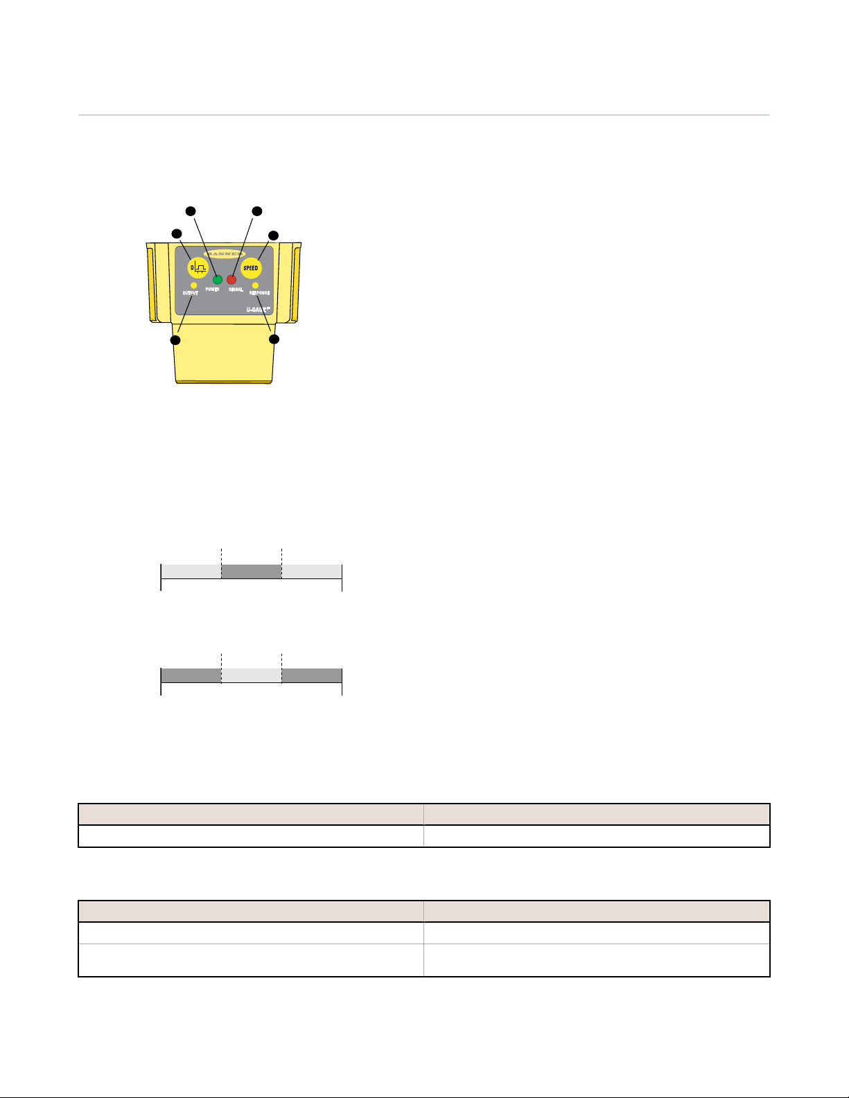
A - TEACH button
B - Sensor power indicator
C - Target signal strength indicator
D - Speed button
E - Output response time indicator
F - Output ON indicator
Figure 3. Sensor features
Teaching Minimum and Maximum Limits
Teach procedures are identical for window-limit and filllevel control models. Window-limit models function as
shown in the figure on the right, and fill-level control
models function as shown in Figure 5 on page 5. To
readjust minimum or maximum limits, repeat the teach
procedure.
A button click is defined as: 0.04 s. ≤ Click ≤ 0.8 s.
Figure 4. Teaching independent minimum and maximum limits —
1. Enter programming mode.
Action
Push and hold TEACH button for 2 seconds Output LED turns solid red and the sensor waits for first limit
window limit models
Result
2. Teach the first limit.
Action
Position the target for the first limit.
Click the TEACH button. The sensor learns the first limit position and the Output LED
3. Teach the second limit.
4 www.bannerengineering.com - tel: 763-544-3164 P/N 117764 Rev. F
Result
changes to flashing red
Page 5

Pump-In Application
(using Normally Open Output)
Pump-Out Application
(using Normally Closed Output)
Initial Tank Level -
Outputs are INACTIVE
Level Drops Below Far Limit -
Outputs ACTIVATE
Level Rises Above Near Limit -
Outputs DEACTIVATE
1
Flow
Flow
Initial Tank Level -
Outputs are INACTIVE
Level Rises Above Near Limit -
Outputs ACTIVATE
Level Drops Below Far Limit -
Outputs DEACTIVATE
Pump Control
Pump Control
Level Rises Above Near Limit -
Output DEACTIVATES
Level Rises Above Near Limit -
Outputs DEACTIVATE
Initial Tank Level -
Output is INACTIVE
Level Rises Above Near Limit -
Outputs DEACTIVATE
Level Drops Below Far Limit -
Output ACTIVATES
Initial Tank Level -
Outputs are INACTIVE
Level Drops Below Far Limit -
Outputs ACTIVATE
Level Rises Above Near Limit -
Outputs DEACTIVATE
Level Rises Above Near Limit -
Output ACTIVATES
Level Rises Above Near Limit -
Outputs DEACTIVATE
Initial Tank Level -
Output is ACTIVE
Level Rises Above Near Limit -
Outputs DEACTIVATE
Level Drops Below Far Limit -
Output DEACTIVATES
Output OFF Output ON Output OFF
Position
+ 100 mm
Position
- 100 mm
Taught Position
Output ON Output ON
Output OFF
Position
+ 100 mm
Position
- 100 mm
Taught Position
Normally Closed Output
Normally Open Output
U-GAGE QT50UVR Series Sensors
Action Result
Position the target for the second limit.
Click the TEACH button. The sensor stores both limits and Output LED turns solid amber.
The sensor returns to Run mode.
The Fill-Level Control mode provides the switching logic required for fill-level, web tensioning control, and similar
applications. In this mode, the output energizes when the target reaches the first sensing window limit, and stays
energized until the target moves to the second limit. The output then de-energizes at the second limit and does not reenergize until the target moves, again, to the first limit.
Teaching Limits Using the Auto-Window Feature
Figure 6. Using the Auto-Window feature for programming
1. Enter programming mode.
Action
Push and hold TEACH push button for 2 seconds. Output LED turns solid red and the sensor waits for first limit.
Figure 5. Fill-Level Control
Teach procedures are identical for window-limit and filllevel control models. Teaching the same limit twice
automatically centers a 200 mm window on the taught
position. To readjust the sensing midpoint, repeat the teach
procedure.
A button click is defined as: 0.04 s. ≤ Click ≤ 0.8 s.
Result
2. Teach the first limit.
P/N 117764 Rev. F www.bannerengineering.com - tel: 763-544-3164 5
Page 6

Output OFF
Taught Position
(e.g., wall or floor)
Position
-100 mm
Position
+100 mm
Sensor
Output
ON
Sensor
Output
OFF
Any object in this area will switch the output,
whether or not the object returns a good signal to the sensor.
Sensing Range
200 mm
Output ON
QT50U Chemical-Resistant Sensor
Tank Section
O-Ring
O-Ring
Threaded Teflon
Nut (included)
U-GAGE QT50UVR Series Sensors
Action Result
Position the target at the desired midpoint for the sensing
window.
Click the TEACH button. Output LED changes to flashing red
3. Teach the second limit.
Action Result
Without moving the target, click the button again. The sensor stores sensing window and the Output LED turns solid
amber. The sensor returns to Run mode.
Figure 7. An application for Auto-Window feature (retroreflective mode)
Installing the Chemical-Resistant Models
The sensor may be threaded directly into the side of a tank (see dimensions for hole diameter and thread specifications),
or into a non-threaded hole, using the included threaded nut. Recommended through-hole size: 56.5 ± 0.5 mm.
For a non-threaded hole, install an o-ring onto the flange, and insert the flange completely into the hole until the sensor
front surface is against the tank’s exterior surface. Place the other o-ring into the groove on the Teflon nut, and thread the
nut onto the flange. Tighten enough to eliminate gaps between the flange and the tank surface. This will ensure that the orings are fully compressed.
Figure 8. Installing a chemical-resistant sensor model into a threaded hole in a tank
6 www.bannerengineering.com - tel: 763-544-3164 P/N 117764 Rev. F
Page 7

Effective Beam Width
Target Distance
-200 mm
-400 mm
-600 mm
200 mm
400 mm
0
600 mm
800 mm
1000 mm
-800 mm
-1000 mm
0 1 m
(3.3')
2 m
(6.6')
3 m
(9.8')
4 m
(13.1')
5 m
(16.4')
6 m
(19.6')
7 m
(22.9')
8 m
(26.2')
8"
-8"
0
16"
-16"
24"
-24"
31"
-31"
-40"
40"
25 mm Rod
500 mm Plate
-10
-20
-30
10
0
20
30
40
-40
0
Target Distance (m)
Target Rotation (deg)
1 m
(3.3’)
2 m
(6.6’)
3 m
(9.8’)
4 m
(13.1’)
5 m
(16.4’)
6 m
(19.6’)
7 m
(22.9’)
8 m
(26.2’)
U-GAGE QT50UVR Series Sensors
Specifications
Sensing Range
200 mm to 8 m (8 inches to 26 feet)
Supply Voltage
Universal Voltage: 85 to 264 V ac, 50/60 Hz / 48 to 250 V dc (1.5
watts maximum, exclusive of load)
Supply Protection Circuitry
Protected against transient over-voltages; DC wiring is without regard
to polarity
Ultrasonic Frequency
75 kHz burst, rep. rate 96 ms
Delay at Power-up
1.5 seconds
Output Configuration
SPDT (Single-Pole, Double-Throw) electromechanical relay output
Output Ratings
Max. switching power (resistive load): 2000 VA, 240 W (1000 VA,
120 W for sensors with Micro-style QD)
Max. switching voltage (resistive load): 250 V ac, 125 V dc
Max. switching current (resistive load): 8 A at 250 V ac, 8 A at 30
V dc derated to 200 mA at 125 V dc (4 A max. for sensors with Microstyle QD)
Min. voltage and current: 5 V dc, 10 mA
Mechanical life of relay: 50,000,000 operations
Electrical life of relay at full resistive load: 100,000 operations
Output Response Time
Selectable 1600 ms, 400 ms or 100 ms
Temperature Effect
Uncompensated: 0.2% of distance/°C
Compensated: 0.02% of distance/°C
Hysteresis
Window-Limit Sensor Models: 5 mm
Fill-Level Control Sensor Models: 0 mm
Repeatability
1.0 mm
Minimum Window Size
20 mm
Adjustments
Sensing Limits: TEACH-Mode programming of near and far limits
Sensor Configuration: Output response time and temperature
compensation mode
Factory Default Settings: 400 ms output response; Temperature
compensation enabled
Indicators
Green Power On LED: Indicates power is ON.
Red Signal LED: Indicates target is within sensing range, and the
condition of the received signal.
Output indicator (bicolor amber/red): Indicates output status or TEACH
mode.
Response indicator (bicolor amber/red): Indicates output response time
selection.
Construction
Transducer: Ceramic/Epoxy composite
Housing: ABS
Membrane Switch: Polyester
CRFV Models: Teflon face, flange, hex nut and transducer coating;
Viton® o-ring
Operating Conditions
Temperature: −20 °C to +70 °C (−4 °F to +158 °F)
Maximum Relative Humidity: 100%
Connections
2 m (6.5 ft) or 9 m (30 ft) shielded 5-conductor (with drain) PVC
jacketed attached cable or 5-pin Micro-style quick-disconnect or 5-pin
Mini-style quick-disconnect fitting.
Environmental Rating
Leakproof design is rated IEC IP67; NEMA 6P
Vibration and Mechanical Shock
All models meet Mil Std. 202F requirements. Method 201A (vibration:
10 to 60 Hz max., double amplitude 0.06", maximum acceleration
10G). Also meets IEC 947-5-2 requirements: 30G 11 ms duration, half
sine wave.
Temperature Warmup Drift
Less than 1.0% of sensing distance upon power-up with Temperature
Compensation enabled
Application Notes
Objects passing inside the specified minimum sensing distance (200
mm) may produce a false response.
Certifications
Performance Curves
QT50U Effective Beam Pattern
P/N 117764 Rev. F www.bannerengineering.com - tel: 763-544-3164 7
QT50U (with 500 mm Plate) Maximum Target
Rotation Angle
Page 8

67.4 mm
[2.66”]
38.1 mm
[1.5”]
18 mm
[0.71”]
66 mm
[2.6”]
84.2 mm
[3.32”]
33 mm
[1.3”]
Temperature
Sensor Location
Internal thread 1/2” NPSM
External thread M30 x 1.5
37 mm
[1.46”]
4x 4.4 mm dia
[0.17” dia]
50.8 mm
[2”]
50.8 mm
[2”]
34.2 mm
[1.35”]
34.2 mm
[1.35”]
U-GAGE QT50UVR Series Sensors
Dimensions
Cabled Models 5-pin Mini-style Models
Chemical-Resistant Models
5-pin Euro-style
Models
74.1 mm (2.92")
67.0 mm (2.64")
M56 x 1.5
35.0 mm (1.38")
10.0 mm (0.39")
8 www.bannerengineering.com - tel: 763-544-3164 P/N 117764 Rev. F
73.1 mm (2.88")
66.0 mm (2.60")
Page 9

Load
bk
ye
bn
bu
wh
85-264V ac, 50/60 Hz
48-250V dc**
shield*
Output Current
8A Max.
bk
ye
bn
bu
wh
shield*
Output Current
(4A or 8A Max.)***
Load
85-264V ac, 50/60 Hz
48-250V dc**
bk
ye
bn
bu
wh
shield*
Output Current
8A Max.
Load
85-264V ac, 50/60 Hz
48-250V dc**
bk
ye
bn
bu
wh
shield*
Load
Output Current
(4A or 8A Max.)***
85-264V ac, 50/60 Hz
48-250V dc**
7/8-16UN-2B
ø 28 mm max.
(1.1")
61 mm max.
(2.4")
4
3
1
5
2
U-GAGE QT50UVR Series Sensors
Wiring
Cabled Models QD Models
Normally Open/Pump-In Normally Open/Pump-In
Normally Closed/Pump-In
* Banner recommends that the shield wire be connected to earth ground.
** DC wiring is without regard to polarity
*** 4 A max. for sensors with Micro-style QD; 8 A max. for sensors with Mini-style QD.
Normally Closed/Pump-In
Accessories
5-Pin Mini-Style Cordsets with Shield
Model Length Style Dimensions Pinout (Female)
MBCC2-506 1.83 m (6 ft)
MBCC2-515 4.57 m (15 ft)
Straight
MBCC2-530 9.14 m (30 ft)
P/N 117764 Rev. F www.bannerengineering.com - tel: 763-544-3164 9
1 = Brown
2 = White
3 = Blue
4 = Black
5 = Yellow
Page 10

42 Typ.
ø 14.5
1/2-20 UNF-28
3
2
5
1
4
38 mm max.
1/2-20UNF-2B
ø 15 mm
38 mm
max.
67
58
29
B
A
70
57
A
B
C
57
ø 49.8 mm
(1.96")
49.4 mm
1.94"
25.0 mm
(0.98")
10.0 mm
(0.39")
65.0 mm
(2.56")
64.0 mm
(2.52")
2" NPT Threads
U-GAGE QT50UVR Series Sensors
5-Pin Micro-Style Cordsets with Shield
Model Length Style Dimensions Pinout (Female)
MQVR3S-506 1.83 m (6 ft)
MQVR3S-515 4.57 m (15 ft)
Straight
MQVR3S-530 9.14 m (30 ft)
MQVR3S-506RA 1.83 m (6 ft)
1 = Brown
2 = White
3 = Yellow
4 = Black
5 = Blue
MQVR3S-515RA 4.57 m (15 ft)
Right Angle
MQVR3S-530RA 9.14 m (30 ft)
Brackets
SMB30SC
• Swivel bracket with 30 mm
mounting hole for sensor
• Black reinforced
thermoplastic polyester
• Stainless steel mounting and
swivel locking hardware
included
Hole center spacing: A=ø 50.8
Hole size: A=ø 7.0, B=ø 30.0
SMB30MM
• 12-ga. stainless steel bracket
with curved mounting slots
for versatile orientation
• Clearance for M6 (¼ in)
hardware
• Mounting hole for 30 mm
sensor
Hole center spacing: A = 51, A to B = 25.4
Hole size: A = 42.6 x 7, B = ø 6.4, C = ø 30.1
SAFQT50U • PVC mounting flange mounts to the front of a QT50U sensor (not
for use with chemical-resistant models).
• Adapts sensor to thread into standard 50.8 mm (2 in) NPT female
threads
10 www.bannerengineering.com - tel: 763-544-3164 P/N 117764 Rev. F
Page 11

U-GAGE QT50UVR Series Sensors
SAFQT50U • PVC mounting flange mounts to the front of a QT50U sensor (not
for use with chemical-resistant models).
• Adapts sensor to thread into standard 50.8 mm (2 in) NPT female
threads
1. Place o-ring in flange groove.
2. Assemble sensor onto threaded flange as shown, using the M4 screws
supplied with the QT50U sensor.
3. Using the supplied hex wrench, torque screws to approximately 1.1 kg/m
(10 in/lbs).
4. Mount sensor/flange assembly into the 50.8 mm (2 in) NPT fitting.
Banner Engineering Corp Limited Warranty
Banner Engineering Corp. warrants its products to be free from defects in material and workmanship for one year following
the date of shipment. Banner Engineering Corp. will repair or replace, free of charge, any product of its manufacture
which, at the time it is returned to the factory, is found to have been defective during the warranty period. This warranty
does not cover damage or liability for misuse, abuse, or the improper application or installation of the Banner product.
THIS LIMITED WARRANTY IS EXCLUSIVE AND IN LIEU OF ALL OTHER WARRANTIES WHETHER EXPRESS OR
IMPLIED (INCLUDING, WITHOUT LIMITATION, ANY WARRANTY OF MERCHANTABILITY OR FITNESS FOR A
PARTICULAR PURPOSE), AND WHETHER ARISING UNDER COURSE OF PERFORMANCE, COURSE OF DEALING OR
TRADE USAGE.
This Warranty is exclusive and limited to repair or, at the discretion of Banner Engineering Corp., replacement. IN NO
EVENT SHALL BANNER ENGINEERING CORP. BE LIABLE TO BUYER OR ANY OTHER PERSON OR ENTITY FOR
ANY EXTRA COSTS, EXPENSES, LOSSES, LOSS OF PROFITS, OR ANY INCIDENTAL, CONSEQUENTIAL OR
SPECIAL DAMAGES RESULTING FROM ANY PRODUCT DEFECT OR FROM THE USE OR INABILITY TO USE THE
PRODUCT, WHETHER ARISING IN CONTRACT OR WARRANTY, STATUTE, TORT, STRICT LIABILITY,
NEGLIGENCE, OR OTHERWISE.
Banner Engineering Corp. reserves the right to change, modify or improve the design of the product without assuming any
obligations or liabilities relating to any product previously manufactured by Banner Engineering Corp.
www.bannerengineering.com - tel: 763-544-3164
 Loading...