

Page 1
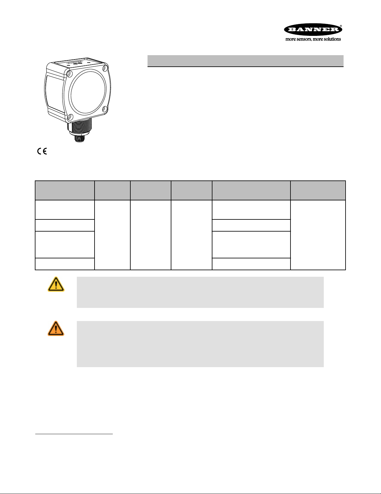
R-GAGE™ QT50RAF Sensor
Radar-Based Adjustable Field Sensors for Detection of Moving and Stationary Targets
Features
• FMCW (true-presence) radar detects moving and stationary objects
• Adjustable sensing field — ignores objects beyond setpoint
• Easy setup and configuration of range, sensitivity, and output with simple DIP
switches
• Sensing functions are unaffected by wind, falling rain or snow, fog, humidity, air
temperatures, or light
• Sensor operates in Industrial, Scientific, and Medical (ISM) telecommunication
band; no special license required
• Rugged IP67 housing withstands harsh environments
Protected by US patents
Models
Models
1
Maximum
Range
Connection
QT50RAF-US
QT50RAF-CN Telecom approved for China
15 m (49 ft)
QT50RAF-EU
5-wire 2 m (6.5
ft) Integral ca-
ble
Supply Voltage
12 to 30V dc
Telecom Approval
2
Telecom approved for US, Can-
ada, and Brazil
Telecom approved for Europe
(except UK), Australia, New
Zealand, China, and Japan
QT50RAF-UK Telecom approved for UK
CAUTION: Make No Modifications to this Product
Any modifications to this product not expressly approved by Banner Engineering could void the user's authority to operate the product. Contact the Factory for more information.
WARNING: Not To Be Used for Personnel Protection
Never use this device as a sensing device for personnel protection. Doing so could lead to serious
injury or death. This device does NOT include the self-checking redundant circuitry necessary to allow its
use in personnel safety applications. A sensor failure or malfunction can cause either an energized or deenergized sensor output condition.
Output
Bipolar NPN/PNP
DIP-switch-selectable
N.O. or N.C.
1
Cabled models only are listed. For integral 5-pin Euro-style (M12) quick-disconnect fitting, add suffix "Q" to the model
number (e.g., QT50RAFQ-xx). QD models require a mating cordset; see Quick Disconnect (QD) Cordsets on page 7.
2
For additional countries, contact Banner Engineering.
P/N 135460_web
Rev. E
11/15/2012
Page 2
D
X Y
Setpoint
R-GAGE™ QT50RAF Sensor
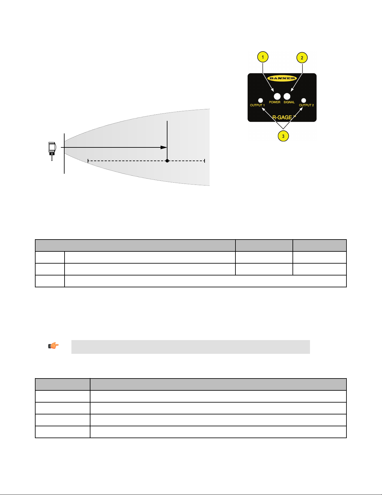
Overview
The R-GAGE sensor emits a well-defined beam of high-frequency radio waves
from an internal antenna. Some of this emitted energy reflects back to the receiving antenna. Signal processing electronics in the sensor determine the distance from the sensor to the object based on the time delay of the return signal. The sensor can be configured (via DIP switches) to sense objects up to a
specific distance, ignoring objects beyond this distance (also called background suppression).
Figure 1. R-GAGE Setpoint
Figure 2. R-Gage Features
1. Power LED: Green (power ON)
2. Signal Strength LED: Red (flashes in proportion
to the signal strength)
3. Output LEDs: Yellow (output energized); Red
(configuration)
Access DIP switches behind threaded cap on sensor
back (not shown)
R-GAGE setpoint distances, minimum and maximum (sensor will detect objects up to setpoint and ignore objects beyond the setpoint)
EU, CN Models US, UK Models
X Minimum setpoint distance 2 m (6.6 ft) 3 m (9.8 ft)
Y Maximum setpoint distance 15 m (49.2 ft) 15 m (49.2 ft)
D Dead Zone*
* Typical dead zone: 0.4 m (1.3 ft) for moving and 1.0 m (3.3 ft) for stationary targets, but varies with target reflectivity
Sensor Configuration
The sensing zone distance, sensitivity, and output configuration can be selected via the DIP switches on the back of the sensor.
Use the included spanner to open the screw-off cover on the back of the sensor and access the DIP switches.
Important: Tighten the DIP switch cover a full quarter turn after contact to maintain the watertight seal.
DIP Switch Functions
Switch Function
1, 2, 3 Sensing distance (detects objects from sensor face to this point)
4, 5, 6 Sensitivity (higher sensitivity sees weaker objects and has a larger beam pattern)
7 Normally open/normally closed output functionality
8 Response Speed
DIP switch 1 is on the left and DIP switch 8 is on the right.
2 www.bannerengineering.com - tel: 763-544-3164 P/N 135460_web
Rev. E
Page 3
R-GAGE™ QT50RAF Sensor
Distance Settings
* Default settings
Switch 1 Switch 2 Switch 3
0 0 0 2 m (6.6 ft) 3 m (9.8 ft)
0 0 1 3 m (9.8 ft) 4 m (13.1 ft)
0 1 0 4 m (13.1 ft) 5 m (16.4 ft)
0 1 1 6 m (19.7 ft) 6 m (19.7 ft)
1* 0* 0* 8 m (26.2 ft) 8 m (26.2 ft)
1 0 1 10 m (32.8 ft) 10 m (32.8 ft)
1 1 0 12 m (39.4 ft) 12 m (39.4 ft)
1 1 1 15 m (49.2 ft) 15 m (49.2 ft)
NOTE: Highest sensitivity is achieved only if sensing distance is 8 m (26.2 ft) or less
Sensitivity Selection
* Default settings
Switch 4 Switch 5 Switch 6 Sensitivity
Distance
EU, CN Models US, UK Models
0* 0* 0* 8 (Highest)
0 0 1 7
0 1 0 6
0 1 1 5
1 0 0 4
1 0 1 3
1 1 0 2
1 1 1 1 (Lowest)
NOTE: Use the sensitivity selection to ignore unwanted weak reflections within the field of view, and not to
narrow the beam width. Narrow-beam R-GAGE sensor models are available.
Output Configuration
* Default settings
Switch 7 Normally Open/Normally Closed
0* N.O.
1 N.C.
P/N 135460_web
Rev. E
www.bannerengineering.com - tel: 763-544-3164 3
Page 4

R-GAGE™ QT50RAF Sensor
Response Speed
* Default settings
Switch 8 ON OFF ON/OFF
0 32 ms 68 ms 100 ms
1* 258 ms 998 ms 1256 ms
Specifications
Range
The sensor is able to detect a proper object (see Detectable Objects) from 1 to 15 m (3.3 to 49.2 ft), depending on target
Detectable Objects
Objects containing metal, water, or similar high-dielectric materials
Operating Principle
Frequency modulated continuous-wave (FMCW) radar
Operating Frequency
24.00 to 24.25 GHz, ISM Band (varies slightly with
model, depending on national telecom regulations)
Supply Voltage
12 to 30V dc, less than 100 mA, exclusive of load
Supply Protection Circuitry
Protected against reverse polarity and transient overvoltages
Delay at Power-up
Less than 2 seconds
Output Configuration
Bipolar NPN/PNP output, 150mA; DIP switch 7 selects
N.O. (default) or N.C. operation
Output Protection
Protected against short circuit conditions
Response Time
DIP-Switch 8 selects ON/OFF response time
Indicators
Power LED: Green (power ON)
Signal Strength LED: Red, flashes in proportion to
signal strength. Steady on at 4x excess gain. Only indicates signal amplitude, not target distance.
Output LEDs: Yellow (output energized) / Red (configuration)
See Figure 2. R-Gage Features on page 2
Adjustments
DIP-switch-configurable sensing distance, sensitivity,
response time, and output configuration
Construction
Housing: ABS/polycarbonate
Lightpipes: Acrylic
Access Cap: Polyester
Operating Temperature
−40° to +65° C (−40° to +149° F)
Environmental Rating
IP67
Connections
Integral 5-wire 2 m (6.5 ft) cable or M12 Euro-style QD
fitting. QD models require a mating cordset
Certifications
ETSI/EN 300 440; FCC part 15; RSS-210; ANATEL
Category II; CMII Category G; ARIB STD T-73; for others, contact Banner Engineering.
FCC ID: UE3QT50RUS—This device compiles with Part 15 of the FCC Rules. Operation is subject to the following two conditions; (1)
this device may not cause harmful interference, and (2) this device must accept any interference received, including interference that may
cause undesired operation.
Este equipamento opera em caráter secundário, isto é, não tem direito à proteção
contra interferência prejudicial, mesmo de estações do mesmo tipo e não pode causar interferência a sistemas operando em caráter primário.
4 www.bannerengineering.com - tel: 763-544-3164 P/N 135460_web
Rev. E
Page 5

5 m
0
-5 m
-10 m
-15 m
10 m
15 m
5 m0 10 m 15 m 20 m 25 m 30 m
2
3
4
5
1
6
7
8
0 4 m 8 m
12 m
16 m
2 m
0
-2 m
-4 m
-6 m
-8 m
4 m
6 m
8 m
2
3
4
1
R-GAGE™ QT50RAF Sensor
Windows
The R-GAGE sensor can be placed behind a glass or a plastic window, but the configuration must be tested and the distance from the
sensor to the window must be determined and controlled prior to installation. There is typically a 20% signal reduction when the sensor is
placed behind a window.
Polycarbonate at 4mm thickness performs well in most situations, but the performance depends on filler materials. Thinner (1 to 3 mm)
windows have high reflection. The amount of reflection depends on the material, thickness, and distance from the sensor to the window.
Locate the sensor in a position of minimum reflection from the window, which will repeat every 6.1 mm of distance between the sensor
and the window. The positions of maximum reflection from the window repeat between the minimums, and decrease in effect until the
window is approximately 150 mm (5.9 in) away. Consult the factory for pre-tested window materials which can be used at any distance
without issue.
Additionally, the face of the window should be protected from flowing water and ice by use of a flow diverter or hood directly above the
window. Falling rain or snow in the air in front of the window, light water mist, or small beads on the face of the window are typically not
an issue. However, a thick, continuous surface of water or ice directly on the face of the window can be detected as a dielectric boundary.
Beam Pattern
Typical Beam Pattern (with BRTR-CC20E Radar Target, Radar
Cross Section = 50 m2)
Left-Right Beam Pattern
Distance
Typical Beam Pattern (with 4 different targets) at highest sensitivity level
Left-Right Beam Pattern
Distance
1–8: Indicates sensitivity level 1: Weak Object (Radar cross section = 0.25 m2)
2: Car (Radar cross section = 3 m2)
3: Large Truck (Radar cross section = 50 m2)
4: Passenger Train (Radar cross section = 300 m2)
P/N 135460_web
Rev. E
NOTE: The effective beam pattern depends on the sensitivity level and target properties.
www.bannerengineering.com - tel: 763-544-3164 5
Page 6

38.1 mm
(1.50")
46.1 mm
(1.82")
R45.0 mm
(R1.77")
66.0 mm
(2.60")
33.0 mm
(1.30")
37.0 mm
(1.46")
74.1 mm
(2.92")
50.8 mm
(2.00")
50.8 mm
(2.00")
19.7 mm
(0.78")
37.0 mm
(1.46")
M30 X 1.5
ISO-6g
4X Ø4.4 mm
(Ø 0.17")
34.2 mm
(1.35")
R-GAGE™ QT50RAF Sensor
Dimensions
Hookup
Wiring Key:
1 = Brown
2 = White
3 = Blue
4 = Black
5 = Gray (Do not connect)
NOTE: Banner recommends that the shield wire (QD cordsets only) be connected to earth ground or dc common. Shielded cordsets are recommended for all QD models.
6 www.bannerengineering.com - tel: 763-544-3164 P/N 135460_web
Rev. E
Page 7

44 Typ.
ø 14.5
M12 x 1
2
3
4
1
5
32 Typ.
[1.26"]
30 Typ.
[1.18"]
ø 14.5 [0.57"]
M12 x 1
67
58
29
B
A
70
57
A
B
C
57
R-GAGE
™ QT50RAF Sensor
Quick Disconnect (QD) Cordsets
5-Pin Threaded M12/Euro-Style Cordsets with Shield
Model Length Style Dimensions Pinout
MQDEC2-506 1.83 m (6 ft)
MQDEC2-515 4.57 m (15 ft)
MQDEC2-530 9.14 m (30 ft)
MQDEC2-550 15.2 m (50 ft)
MQDEC2-506RA 1.83 m (6 ft)
MQDEC2-515RA 4.57 m (15 ft)
MQDEC2-530RA 9.14 m (30 ft)
MQDEC2-550RA 15.2 m (50 ft)
NOTE: Pin 5 is not used.
Mounting Brackets
SMB30SC
• Swivel bracket with 30 mm
mounting hole for sensor
• Black reinforced thermoplastic polyester
• Stainless steel mounting
and swivel locking hardware included
Hole center spacing: A=ø 50.8
Hole size: A=ø 7.0, B=ø 30.0
Straight
Right-Angle
1 = Brown
2 = White
3 = Blue
4 = Black
5 = Gray
SMB30MM
• 12-ga. stainless steel
bracket with curved
mounting slots for versatile
orientation
• Clearance for M6 (¼ in)
hardware
• Mounting hole for 30 mm
sensor
Hole center spacing: A = 51, A to B = 25.4
Hole size: A = 42.6 x 7, B = ø 6.4, C = ø 30.1
Weather Deflector
QT50RCK
• Required if the R-GAGE is exposed to rain or snow
• Prevents buildup of water or ice from interfering with sensor
performance
Banner Engineering Corp Limited Warranty
Banner Engineering Corp. warrants its products to be free from defects in material and workmanship for one year following the date of
shipment. Banner Engineering Corp. will repair or replace, free of charge, any product of its manufacture which, at the time it is returned
to the factory, is found to have been defective during the warranty period. This warranty does not cover damage or liability for misuse,
abuse, or the improper application or installation of the Banner product.
P/N 135460_web
Rev. E
www.bannerengineering.com - tel: 763-544-3164 7
Page 8

R-GAGE™ QT50RAF Sensor
THIS LIMITED WARRANTY IS EXCLUSIVE AND IN LIEU OF ALL OTHER WARRANTIES WHETHER EXPRESS OR IMPLIED (INCLUDING, WITHOUT LIMITATION, ANY WARRANTY OF MERCHANTABILITY OR FITNESS FOR A PARTICULAR PURPOSE), AND
WHETHER ARISING UNDER COURSE OF PERFORMANCE, COURSE OF DEALING OR TRADE USAGE.
This Warranty is exclusive and limited to repair or, at the discretion of Banner Engineering Corp., replacement. IN NO EVENT SHALL
BANNER ENGINEERING CORP. BE LIABLE TO BUYER OR ANY OTHER PERSON OR ENTITY FOR ANY EXTRA COSTS, EXPENSES, LOSSES, LOSS OF PROFITS, OR ANY INCIDENTAL, CONSEQUENTIAL OR SPECIAL DAMAGES RESULTING FROM ANY
PRODUCT DEFECT OR FROM THE USE OR INABILITY TO USE THE PRODUCT, WHETHER ARISING IN CONTRACT OR WARRANTY, STATUTE, TORT, STRICT LIABILITY, NEGLIGENCE, OR OTHERWISE.
Banner Engineering Corp. reserves the right to change, modify or improve the design of the product without assuming any obligations or
liabilities relating to any product previously manufactured by Banner Engineering Corp.
 Loading...