

Page 1
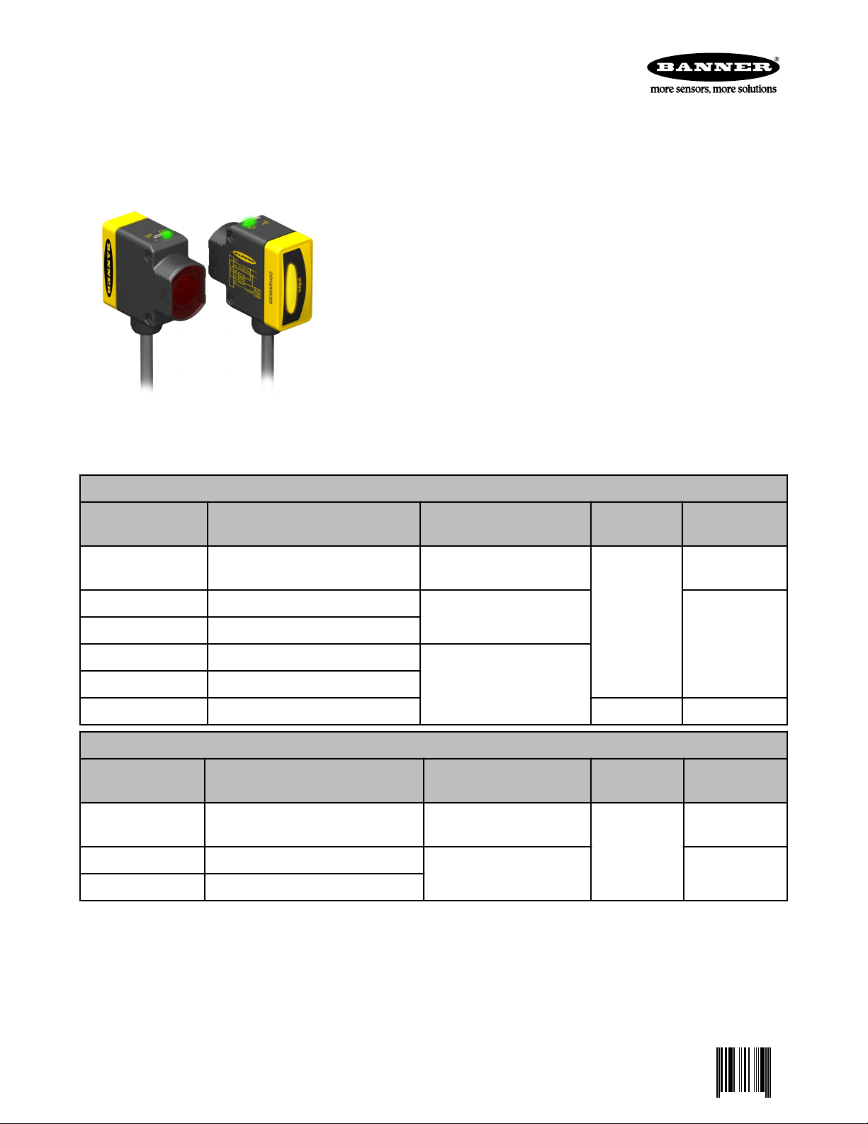
WORLD-BEAM QS30H2O Series
0 136166 7
High-Power Water Sensor
For the latest technical information about this product, including specifications, dimensions, and wiring, see www.BannerEngineering.com
Features
• Special emitter/receiver infrared wavelength tuned to the absorption band of water
• Powerful enough to burn through many types of plastic and glass containers
• Water-based liquids will attenuate the signal; this enhances contrast on difficult
sensing applications found on bottle-filling lines
• Excellent noise immunity and crosstalk avoidance
• Easy-to-read operating status indicators
• Bipolar discrete outputs, PNP and NPN; analog model also available
• Light Operate and Dark Operate models available
• Models available with 2 m or 9 m (6.5' or 30') cable, or 150 mm (6") pigtail with
quick-disconnect fitting
• Rugged IP67 (NEMA 6) housing for harsh environments; 1200 psi washdown rated per NEMA PW12
• Compact housing, mounting versatility — 30 mm threaded barrel- or side-mount
Models
Standard Models**
Model* Description Sensing Beam
and Range†
QS30EXH2O Emitter
QS30ARH2O Receiver, light operate
QS30RRH2O Receiver, dark operate
QS30ARXH2O High-gain receiver, light operate
QS30RXH2OU High-gain receiver, analog 15 to 30V dc 0-10V Analog
Super High-Power Models**
Model* Description Sensing Beam
QS30EXSH2O Super high-power emitter
QS30ARXSH2O Super high-power receiver, light operate
QS30RRXSH2O Super high-power receiver, dark operate
* Only 2 m (6') cables are listed. For 9 m (30') cable, add suffix “W/30” to the model number (e.g., QS30EH2O W/30). For 150 mm (6.5")
pigtail with a 5-pin Euro-style connector, add suffix “Q5” to the model number (e.g., QS30EH2OQ5). A model with a QD
connector requires a mating cordset (see Quick-Disconnect (QD) Cordsets on page 7).
** Standard emitters will only work with standard receivers. Super High-Power emitters will only work with Super High-Power receivers.
† Sensors can be used at ranges greater than listed for applications that require less excess gain. Please consult the
factory for assistance on your long-range applications.
1450 nm infrared
13 mm effective beam dia.
2 m (6.5') range
4 m (13') rangeQS30RRXH2O High-gain receiver, dark operate
and Range†
1450 nm infrared
13 mm effective beam dia.
8 m (26') range
Supply
Voltage
10 to 30V dc
Supply
Voltage
10 to 30V dc
Output
--
Bipolar (NPN and
PNP)
Output
--
Bipolar (NPN and
PNP)
P/N 136166 rev. C 10/7/2011
Page 2
WORLD-BEAM QS30H2O Series
WARNING: Not To Be Used for Personnel Protection
Never use this product as a sensing device for personnel protection. Doing so could lead to seri-
ous injury or death. This product does NOT include the self-checking redundant circuitry necessary to
allow its use in personnel safety applications. A sensor failure or malfunction can cause either an energized or de-energized sensor output condition.
Overview
The Banner QS30H2O series water sensor was developed to detect the presence of water. Its electro-optical components are tuned to one absorption
band of water in the long infrared spectrum. The emitted infrared light penetrates many types of plastic and glass containers, but will not pass through
water-based fluids, nor through opaque substances such as wood, metal or
cardboard. Accessory apertures are available to attenuate or shape the beam
for low-gain applications, for example, clear water in a clear bottle.
Low-gain models are recommended for sensing applications where the liquid
container is transparent or when the thickness of liquid being detected is
small. Some examples are clear glass test tubes and clear PET beverage bottles. High-gain models are recommended when the liquid container is lightblocking (translucent) and when the thickness of liquid being detected is large.
Some examples are HDPE milk containers, colored PET beverage bottles,
and etched glass containers. Super High-Power models are recommended for
thick, opaque containers that require maximum burn-through power at a slower response speed.
For all applications, the sensors must be installed to maximize the optical contrast between the clear and blocked states. The installer can use apertures
and mechanical alignment of the sensors to achieve the best results (see
page 3). The QS30H2O sensor enhances the available contrast by taking advantage of the absorption band of water.
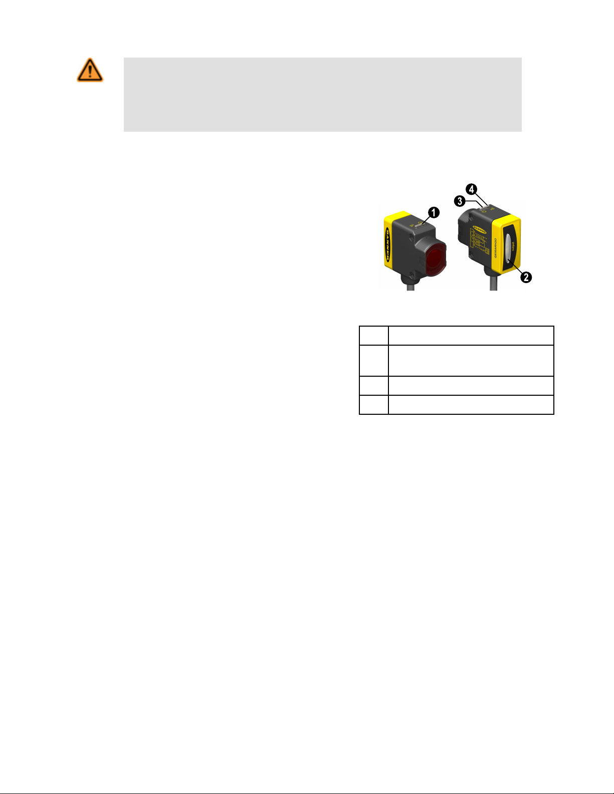
Figure 1. Features
1 Emitter Power LED (Green)
2 Output Conducting (Yellow, Discrete Mod-
els Only)
3 Receiver Power LED (Green)
4 AID Indicator (Yellow)
For advanced applications, a 0–10V analog output is available. The analog output allows the user to directly measure the amount of
signal attenuation. The analog output value can be filtered and a switching threshold determined in a PLC or computer as required for the
application. Please consult the factory for more information on using the analog output.
Each discrete output model has two bipolar outputs that switch simultaneously: one each NPN (sinking) and PNP (sourcing). Light Operate and Dark Operate models are available.
The versatile housing provides multiple mounting configurations in a minimum of space. These sensors are extremely rugged, powerful
and leakproof, with epoxy-encapsulated electronics for maximum resistance to mechanical shock and vibration. They are powerful
enough to burn through dust and many types of industrial and process contamination.
The sensors’ innovative circuitry provides excellent EMI/RFI noise immunity. For applications where optical crosstalk between multiple
sensor pairs may be a problem, either of two modulation frequencies may be selected. (Set each emitter to the same frequency as its
receiver, via the sensor hookup; see Figure 2. Sensor Alignment Procedure on page 3 or Hookups on page 7.)
Indicators
Each sensor has a green Power ON/OFF indicator, visible from 360° (see Figure 1). Receivers also have a yellow AID indicator that
flashes to show signal strength. (The higher the flash rate, the more light is received; a solid AID LED indicates excellent signal.) Discrete
models also have a large yellow LED that lights when an output is conducting.
Sensor Configuration
Teaching Limits
Discrete models require no configuration; simply align the emitter to the receiver to maximize contrast between the clear and blocked
conditions (see Figure 2. Sensor Alignment Procedure on page 3).
2 www.bannerengineering.com - tel: 763-544-3164 P/N 136166 rev. C
Page 3
10V dc
0V dc
Positive
Slope
Negative
Slope
ClearBlocked
Signal
WORLD-BEAM QS30H2O Series
For analog models in high-contrast applications, alignment may be the only configuration needed. For more challenging applications using analog models, use the TEACH procedure to maximize contrast. This procedure is accomplished by pulsing the receiver’s white wire
(see Hookups on page 7 and teach procedure on page 4). Analog output slope also can be inverted from positive to negative or back.
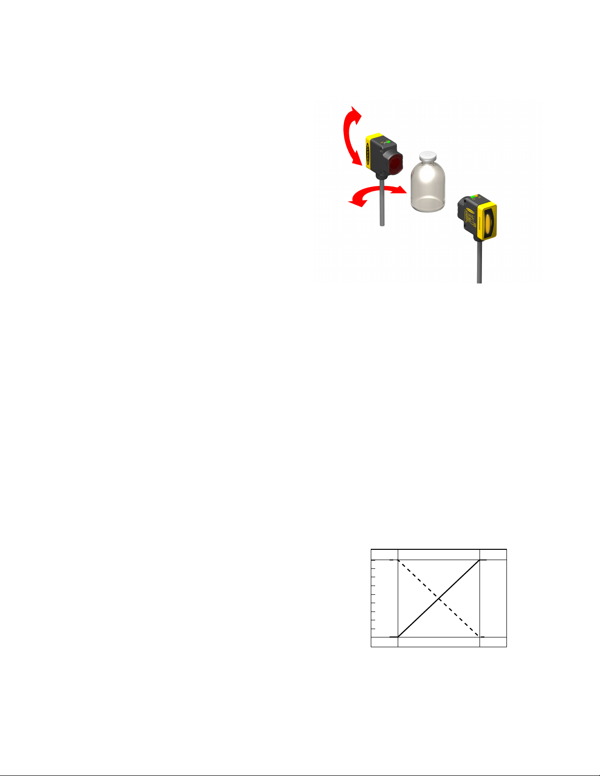
Sensor Alignment — When Empty Container Can Be Presented
1. Position both the emitter and the receiver loosely in their mounting position. See Figure 2.
2. Present the “clear” condition for the application (an empty container).
3. Verify that both emitter and receiver are wired for the same
modulation frequency (see below).
4. Adjust the emitter first, then the receiver. Adjust the emitter’s position until the receiver AID indicator is ON steady, or is flashing
at its fastest rate.
5. Tighten the emitter mounting hardware, then repeat step 4 for
the receiver.
6. Block the sensor beam with the target and verify that the output
changes state.
Figure 2. Sensor Alignment Procedure
Sensor Alignment — When Empty Container Cannot Be Presented
For this procedure, the clear condition is no container at all.
1. Mount loosely and mechanically align the emitter and the receiver such that their faces are parallel to one another. (The AID indicator should be ON steady.)
2. Rotate the emitter in one direction until the receiver AID indicator begins to flash. Repeat in the other direction. Position the emitter
midway between those two positions and tighten the emitter mounting hardware.
3. Repeat step 2 for the receiver.
4. Block the sensor beam with the target and verify that the output changes state.
Frequency Selection
The modulation frequency (A or B) is selected by the state of the gray wire (on cabled models; pin 5 on QD models — see Hookups on
page 7). A “+” voltage or no connection selects frequency A; connecting it to “–” selects frequency B. Each emitter must be set to the
same frequency as its receiver.
Emitter Inhibit
To disable (or inhibit) the emitter LED (useful for testing the receiver operation), connect the white wire to “–” voltage.
Analog Static TEACH
Analog TEACH is performed remotely, by pulsing the white Teach wire (see
Hookups).
Restore Factory TEACH: Reverts the sensing limits to the factory default limits
(max contrast); output slope is not affected.
Analog Output Slope: Toggles the analog output to send a high signal when
object is absent (positive slope) or present (negative slope). Analog slope can
be selected based on the TEACH order (first taught condition is always 0V; second taught condition is 10V) or by using the slope select procedure below. If the
slope select procedure is used, it must be used after teaching the limits. To determine the current slope setting, measure the output signal during object
present and absent conditions.
Figure 3. Analog Static Teach
P/N 136166 rev. C www.bannerengineering.com - tel: 763-544-3164 3
Page 4

T
1x
T
1x
T
1x
T T
T
2x
T T
T
T
T
3x
WORLD-BEAM QS30H2O Series
Step
Access TEACH Mode/
Learn 1st Condition
0.04 seconds
• Present 1st condition.
• Single-pulse remote TEACH line.
Learn 2nd Condition
• Present 2nd condition.
• Single-pulse remote TEACH line.
Restore Factory Default (Maximum Contrast) Setting
Step
0.04 seconds
Remote Line
< T < 0.8 seconds
Remote Line
< T < 0.8 seconds
Result
Power LED: OFF
AID LED: Double-flash
TEACH Accepted
Power LED: Flashes 3 times, then ON
AID LED: AID mode (flash rate varies depending
upon signal strength)
Sensor returns to RUN mode.
TEACH Not Accepted
Power LED: OFF
AID LED: Single-flash
Sensor returns to “Learn 1st Condition.”
Result
Access TEACH Mode
Restore Factory Default Setting
• Single-pulse remote TEACH line
• Double-pulse remote TEACH line
(Maximum Contrast Setting)
Analog Output Slope Invert
Teach sensing limits before inverting the output slope.
Step
Toggle Analog Output Slope
0.04 seconds
• Triple-pulse remote TEACH line
Remote Line
< T < 0.8 seconds
Power LED: OFF
AID LED: Double-flash
Power LED: Flashes 3 times, then ON
AID LED: AID mode (flash rate varies depend-
ing upon signal strength)
Sensor returns to RUN mode with maximum
contrast setting.
Result
Analog output slope toggles between positive
and negative.
4 www.bannerengineering.com - tel: 763-544-3164 P/N 136166 rev. C
Page 5

WORLD-BEAM QS30H2O Series
Specifications
NOTE: Specifications are subject to change without notice.
Emitter: 10 to 30V dc (10% maximum ripple) at less than 80 mA
Supply Voltage
Discrete Receiver: 10 to 30V dc (10% maximum ripple) at less than 65 mA (exclusive of load)
Analog Receiver: 15 to 30V dc (10% maximum ripple) at less than 65 mA (exclusive of load)
Beam
Sensing Range
Output Configuration
Output Rating
Output Response
Adjustments
1450 nm, infrared
13 mm effective beam diameter
Low-gain models: 2 m (6.5')
High-gain models: 4 m (13')
Super High-Power models: 8 m (26')
Discrete models: Bi-polar current sinking (NPN) white wire; current sourcing (PNP) black wire
Analog models: 0–10V (black wire)
Discrete models: 100 mA maximum load @ 25° C
OFF-state leakage current: less than 10 µA
ON-state saturation voltage:
PNP: less than 1.2V at 10 mA; less than 2.5V at 100 mA
NPN: less than 200 mV at 10 mA; less than 1V at 100 mA
Protected against false pulse on power-up and continuous overload or short circuit
Analog models: 2 KΩ minimum impedance
Discrete models:
10x excess gain or more — Standard models: 1 ms ON and OFF response; 500 µs repeatability
Super High-Power models: 10 ms ON and OFF response; 5 ms repeatability
2x to 10x excess gain — Standard models: 3 ms ON and OFF response; 2.5 ms repeatability
Super High-Power models: 30 ms ON and OFF response; 25 ms repeatability
Analog models: 25 ms for a 95% step change
Light Operate/Dark Operate — depending on model selected
Frequency — selected via gray wire
A: Gray (+)
B: Gray (–)
Emitter only: LED inhibit — selected via white wire
White (–) turns emitter LED OFF (to allow verification of receiver operation)
Green LED on housing top: Power ON
Indicators
Environmental Rating Leakproof design rated IEC IP67 (NEMA 6); PW12 1200 psi washdown per NEMA PW12
Construction
Connection 5-wire 2 m or 9 m cable (6' or 30') or 150 mm (6") pigtail with 5-pin Euro-style quick-disconnect fitting
Operating Conditions
Certifications
P/N 136166 rev. C www.bannerengineering.com - tel: 763-544-3164 5
Receiver only:
Yellow AID LED on housing top: Flashes to indicate signal strength (faster flash = better signal)
Yellow LED (large oval on housing back): Discrete output conducting
Housing: plastic (PC/ABS blend)
Front window: plastic (PMMA -acrylic)
Cable: PVC
Pigtail QD: PVC and nickel-plated brass
Temperature: −20° to +60°C (−4° to +140°F)
Relative Humidity: 95%; non-condensing
Page 6

100
1.0 m
(3.3')
10 m
(33')
0.1 m
(0.3')
1000
10000
100000
1000000
E
X
C
E
S
S
G
A
I
N
DISTANCE
QS30
Opposed Mode
Water Sensor
High Gain
Super
High
Power
Low Gain
8.0 m
(24')
4.0 m
(12')
6.0 m
(18')
2.0 m
(6')
0
0
150 mm
300 mm
450 mm
150 mm
300 mm
450 mm
0
6"
12"
18"
6"
12"
18"
DISTANCE
High Gain
Low Gain
QS30
Opposed Mode
Water Sensor
Super
High
Power
0
1 10 100 1000
20
40
60
80
100
120
10000 100000
H
2
O Thickness (mm)
Excess Gain
1.4 mm
(0.05")
44.0 mm
(1.73")
8.9 mm
(0.35")
33.0 mm
(1.30")
5.5 mm
(0.22")
51.1 mm
(2.01")
54.3 mm
(2.14")
22.0 mm
(0.87")
M30 x 1.5 Thread
max. torque 6 Nm (53 in lbs)
with included
30 mm mounting nut
2 x ø3.3 mm (0.13")
max. torque
0.7 Nm (6 in lbs)
Yellow LED
Output
Indicator
Yellow and Green LEDs
Hardware included:
(2) M3 x 0.5 x 28 stainless steel
machine screws, nuts and washers
Aperture Kit APQS30-DVH
12.5 mm
(0.47")
16 mm
(0.63")
WORLD-BEAM QS30H2O Series
Performance Curves
Excess Gain Beam Pattern H2O Thickness vs. Excess Gain
Dimensions
(Typical for Distilled Water, 100% Blocked
Condition)
6 www.bannerengineering.com - tel: 763-544-3164 P/N 136166 rev. C
Page 7

1
3
10-30V dc
Beam
Inhibit
Frequency Select
2
5
–
+
Load
Load
3
1
2
4
5
10-30V dc
100 mA max. load
Frequency Select
–
+
KEY
1 = Brown
2 = White
3 = Blue
4 = Black
5 = Grey
3
1
2
4
5
15-30V dc
Teach
0-10V
Frequency Select
–
+
1
3
10-30V dc
Beam
Inhibit
Frequency Select
2
5
–
+
Load
Load
3
1
2
4
5
10-30V dc
100 mA max. load
Frequency Select
–
+
KEY
1 = Brown
2 = White
3 = Blue
4 = Black
3
1
2
4
5
15-30V dc
Teach
0-10V
Frequency Select
–
+
M12 x 1
ø 15 mm
(0.6")
44 mm max.
(1.7")
2
3
4
1
5
WORLD-BEAM QS30H2O Series
Hookups
Emitter Receiver - Discrete Receiver - Analog
Frequency A Frequency A Frequency A
Frequency B Frequency B Frequency B
Key
Cable and QD hookups are funcionally identical
1 = Brown
2 = White
3 = Blue
4 = Black
5 = Gray
Quick-Disconnect (QD) Cordsets
Style Model Length Dimensions Pinout
5-pin
Euro-style
straight
MQDC1-506 2 m (6.5')
MQDC1-515 5 m (15')
MQDC1-530 9 m (30')
1 = Brown
2 = White
3 = Blue
4 = Black
5 = Gray
P/N 136166 rev. C www.bannerengineering.com - tel: 763-544-3164 7
Page 8

20°
44.0 mm
R35.0 mm
4.5 mm
24.0 mm
11.0 mm
ø4.3 mm
22.0 mm
64.4 mm
1.9 mm
R33.0 mm
33.0 mm
59.4 mm
24°
20°
4.5 mm
24.0 mm
11.0 mm
44.0 mm
R35.0 mm
ø4.3 mm
22.0 mm
R1.7 mm
R33.0 mm
91.4 mm
1.9 mm
86.4 mm
16 mm
16.35 mm
24.0 mm
35.0 mm
13.3 mm
26.5 mm
18.0 mm
56 mm
7.0 mm
33 mm
17.0 mm
M18 X 1
4 X Ø 3.3 mm
2 X R 33.0 mm
50.8 mm
58.7 mm
66.5 mm
30.0 mm
29.0 mm
12.7 mm
M30 x 1.5
internal
thread
WORLD-BEAM QS30H2O Series
Mounting Brackets
SMBQS30L
SMBQS30Y
• Right-angle bracket for cabled sensors
• 14-gauge stainless steel
• ± 12° tilt adjustment
• Clearance for M4 (#8) hardware
• Heavy-duty die-cast bracket with M18 vertical mounting option
• ± 8° tilt adjustment for cabled sensors
• Nuts and lockwasher included
SMBQS30LT
SMB30SC
• Tall right-angle bracket for QD sensors
with straight cordset connectors
• 14-gauge stainless steel
• ± 8° tilt adjustment
• Swivel bracket with 30 mm mounting
hole for sensor
• Black reinforced thermoplastic polyester
• Stainless steel mounting and swivel
locking hardware included
Other Compatible Mounting Brackets (see Banner Photoelectric catalog for more information):
SMB30MM
SMB30A
SMB30FA
8 www.bannerengineering.com - tel: 763-544-3164 P/N 136166 rev. C
Page 9

WORLD-BEAM QS30H2O Series
Accessory Apertures
Opposed-mode QS30 sensors may be fitted with apertures to narrow or shape the sensor’s effective beam to more closely match the
size or profile of the containers being sensed. A common example is the use of slot type apertures to detect edges of liquid levels.
NOTE: The use of apertures will reduce the excess gain (see attentuation table below).
Model Description
APQS30-040
APQS30-100 2.5 mm (0.10") diameter – 6 each
Circular hole
1 mm (0.04") diameter – 6 each
APQS30-200 5 mm (0.20") diameter – 6 each
APQS30-040H
APQS30-100H 2.5 x 12 mm (0.10" x 0.47") – 6 each
Horizontal slot
1 x 12 mm (0.04" x 0.47") – 6 each
APQS30-200H 5 x 12 mm (0.20" x 0.47") – 6 each
APQS30-040V
APQS30-100V 2.5 x 17 mm (0.10" x 0.67") – 6 each
Vertical slot
1 x 17 mm (0.04" x 0.67") – 6 each
APQS30-200V 5 x 17 mm (0.20" x 0.67") – 6 each
APQS30-DVHX2 Kit containing two of each aperture above – 18 total
APQS30-DVH
Kit (included with each emitter/receiver) containing one each of
aperture models: APQS30-040, APQS30-040H, APQS30-040V
Attenuation Factor
Model
Aperture on Both Emitter and Receiver Aperture on Receiver Only
APQS30-040 5,000 90
APQS30-100 300 20
APQS30-200 20 5
APQS30-040H 60 10
APQS30-100H 13 4
APQS30-200H 4 2
APQS30-040V 60 10
APQS30-100V 13 4
APQS30-200V 4 2
Examples for Apertures and Water Thickness vs. Excess Gain
The QS30EXH2O / QS30RXH2O sensor pair is used with a horizontal aperture model APQS30-040H on the receiver at 1 meter sensing
distance. The excess gain is reduced to approximately 200; 50 mm of water will completely block the signal.
When the same aperture is used on both the emitter and receiver at 1 meter, the excess gain is approximately 40; 35 mm of water
will block the signal.
NOTE: This example does not include the attenuation from the container holding the water.
P/N 136166 rev. C www.bannerengineering.com - tel: 763-544-3164 9
Page 10

WORLD-BEAM QS30H2O Series
Banner Engineering Corp Limited Warranty
Banner Engineering Corp. warrants its products to be free from defects in material and workmanship for one year following the date of
shipment. Banner Engineering Corp. will repair or replace, free of charge, any product of its manufacture which, at the time it is returned
to the factory, is found to have been defective during the warranty period. This warranty does not cover damage or liability for misuse,
abuse, or the improper application or installation of the Banner product.
THIS LIMITED WARRANTY IS EXCLUSIVE AND IN LIEU OF ALL OTHER WARRANTIES WHETHER EXPRESS OR IMPLIED (INCLUDING, WITHOUT LIMITATION, ANY WARRANTY OF MERCHANTABILITY OR FITNESS FOR A PARTICULAR PURPOSE), AND
WHETHER ARISING UNDER COURSE OF PERFORMANCE, COURSE OF DEALING OR TRADE USAGE.
This Warranty is exclusive and limited to repair or, at the discretion of Banner Engineering Corp., replacement. IN NO EVENT SHALL
BANNER ENGINEERING CORP. BE LIABLE TO BUYER OR ANY OTHER PERSON OR ENTITY FOR ANY EXTRA COSTS, EXPENSES, LOSSES, LOSS OF PROFITS, OR ANY INCIDENTAL, CONSEQUENTIAL OR SPECIAL DAMAGES RESULTING FROM ANY
PRODUCT DEFECT OR FROM THE USE OR INABILITY TO USE THE PRODUCT, WHETHER ARISING IN CONTRACT OR WARRANTY, STATUTE, TORT, STRICT LIABILITY, NEGLIGENCE, OR OTHERWISE.
Banner Engineering Corp. reserves the right to change, modify or improve the design of the product without assuming any obligations or
liabilities relating to any product previously manufactured by Banner Engineering Corp.
 Loading...