

Page 1
Printed in USA 08/03 P/N 69950 rev. B
WARNING . . . Not To Be Used for
Personnel Protection
Never use these products as sensing devices for personnel
protection. Doing so could lead to serious injury or death.
These sensors do NOT include the self-checking redundant
circuitry necessary to allow their use in personnel safety
applications. A sensor failure or malfunction can cause either an
energized or de-energized sensor output condition. Consult your
current Banner Safety Products catalog for safety products which
meet OSHA, ANSI and IEC standards for personnel protection.
Page 2

Lens Selection Guide
Table of Contents
General Lens Considerations . . . . . . . . . . . . . . . . . . . . . . . . . . . . . . . . 1
Field of View . . . . . . . . . . . . . . . . . . . . . . . . . . . . . . . . . . . . . . . . . . . . . . 1
Determining Field of View . . . . . . . . . . . . . . . . . . . . . . . . . . . . . . . . . . . 2
FOV Formula . . . . . . . . . . . . . . . . . . . . . . . . . . . . . . . . . . . . . . . . . . . . 2
Calculated FOV Example. . . . . . . . . . . . . . . . . . . . . . . . . . . . . . . . . . . 2
Determining Working Distance . . . . . . . . . . . . . . . . . . . . . . . . . . . . . . . 3
Determining Focal Length . . . . . . . . . . . . . . . . . . . . . . . . . . . . . . . . . . . 4
Focal Length Tools. . . . . . . . . . . . . . . . . . . . . . . . . . . . . . . . . . . . . . . . 4
Focal Length Considerations . . . . . . . . . . . . . . . . . . . . . . . . . . . . . . . . 5
Focal Length and Lens Extension Tables . . . . . . . . . . . . . . . . . . . . . . 6
Focal Length Table, Working Distances in Inches . . . . . . . . . . . . . . . . 6
Lens Extensions Table, Working Distances in Inches . . . . . . . . . . . . . 7
Focal Length Table, Working Distances in Millimeters. . . . . . . . . . . . . 8
Lens Extensions Table, Working Distances in Millimeters . . . . . . . . . . 9
Working Distance vs. FOV Graphs . . . . . . . . . . . . . . . . . . . . . . . . . . . 10
Focal Length Formula . . . . . . . . . . . . . . . . . . . . . . . . . . . . . . . . . . . . . 16
Lens Options Table . . . . . . . . . . . . . . . . . . . . . . . . . . . . . . . . . . . . . . . 17
Index . . . . . . . . . . . . . . . . . . . . . . . . . . . . . . . . . . . . . . . . . . . . . . . . . . . 19
Banner Engineering Corp.
www.bannerengineering.com • Tel: 763.544.3164
•
Minneapolis, MN
•
USA
P/N 69950 rev. B i
Page 3

Lens Selection Guide
ii P/N 69950 rev. B
Banner Engineering Corp.
www.bannerengineering.com • Tel: 763.544.3164
•
Minneapolis, MN
•
USA
Page 4
Lens Selection Guide
General Lens Considerations
There are many lens options to consider, such as focal length, mounting style, and focus
locking. The two most critical lens considerations are mounting style and focal length. Banner
products use C-Mount lenses only. Before selecting the appropriate focal length, Field of View
(FOV) and working distance must be determined.
Banner offers C-Mount lenses of the following focal lengths (in millimeters): 4, 8, 12, 16, 25,
50, and 75. Other manufacturers’ C-Mount lenses may also be used.
The following sections provide a tour through the process of determining the Field of View,
working distance, and focal length:
Determining Field of View
. . . . . . . . . . . . . . . . . . . . . . . . . . . . . . . . . . . . . . page 2
Determining Working Distance
Determining Focal Length
. . . . . . . . . . . . . . . . . . . . . . . . . . . . . . . . . . page 3
. . . . . . . . . . . . . . . . . . . . . . . . . . . . . . . . . . . . . . page 4
For additional help, support is available from your local Banner representative or a Banner
Application Engineer. Application Engineers are available from 8:00
A.M. to 5:30 P.M. Central
Time, Monday through Friday, excluding holidays.
Field of View
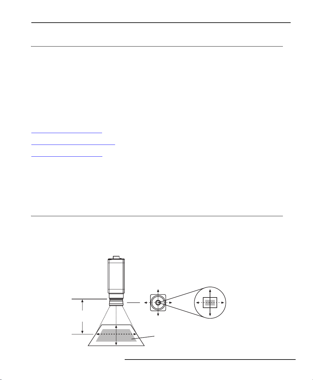
Field of view (FOV) is the area of the inspection captured on the camera’s imager. The size of
the FOV and the size of the camera’s imager directly affect the image resolution (one
determining factor in accuracy). See the illustration below.
NOTE: The PresencePLUS Pro camera imager
size is 640 pixels wide by 480 pixels tall.
Working
Distance
Camera
Lens
480 pixels
(vertical FOV)
640 pixels
(horizontal FOV)
Imager
Banner Engineering Corp.
www.bannerengineering.com • Tel: 763.544.3164
•
Minneapolis, MN
•
USA
Field of View
P/N 69950 rev. B 1
Page 5

Lens Selection Guide
Determining Field of View
To determine FOV size: Measure the size of the inspection area (inches or millimeters), and
allow extra area to accommodate any anticipated movement of the target object.
To verify that the FOV is sufficient for the required resolution:
1. Estimate the required resolution or minimum detection size; for example, will the inspection
measure to a tolerance of 0.1 mm? 1 inch? 10 feet?
2. Use the FOV Formula below to determine the maximum horizontal and vertical FOV that will
maintain the required resolution.
3. Verify that the calculated FOV is larger than the inspection area.
FOV Formula
Required Resolution x 640 pixels = Maximum Horizontal FOV
Required Resolution x 480 pixels = Maximum Vertical FOV
Calculated FOV Example
Approximate area of inspection is 3.0" by 3.5". Required resolution is 0.01".
For the required resolution, is the area of inspection an acceptable FOV?
Required Resolution x 640 pixels = Maximum Horizontal FOV.
0.01" x 640 = 6.4" Maximum Horizontal FOV.
Required Resolution x 480 pixels = Maximum Vertical FOV.
0.01" x 480 = 4.8" Maximum Vertical FOV.
The Calculated FOV (6.4" x 4.8") is larger than the area of inspection;
therefore, a 3.0" x 3.5" FOV is acceptable.
If the calculated FOV is smaller than the desired area of inspection, options are as follows:
• Use multiple cameras.
• Inspect a smaller portion of the area.
• Reduce the resolution requirement.
Banner Engineering Corp.
www.bannerengineering.com • Tel: 763.544.3164
•
Minneapolis, MN
2 P/N 69950 rev. B
•
USA
Page 6
Lens Selection Guide
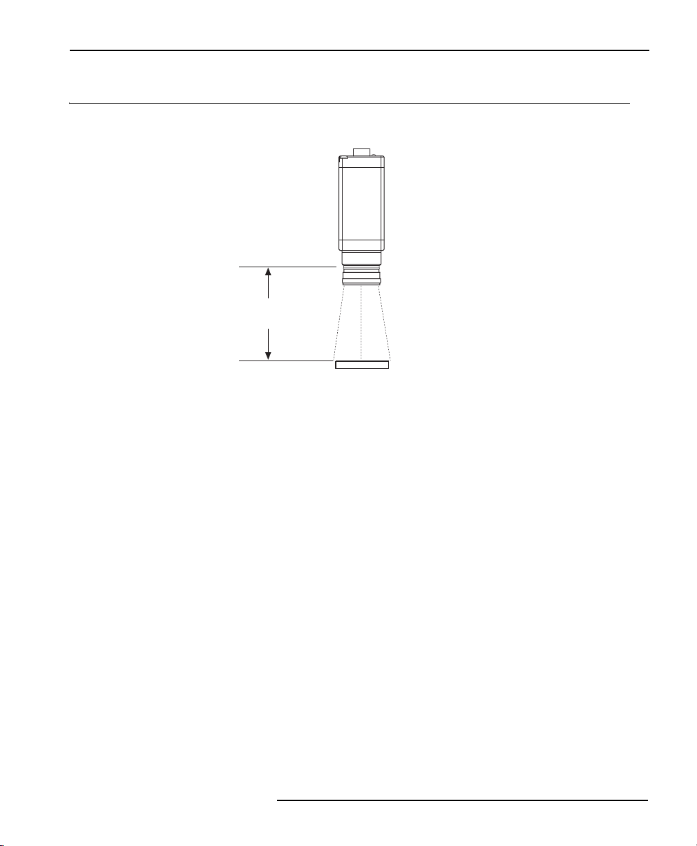
Determining Working Distance
Working distance is the distance between the back of the lens and the target object.
Camera
Working
Distance
Target Object
Some of the key factors that can restrict working distance are as follows:
• The minimum working distance of Banner’s standard lenses is about 2.5 inches. Banner’s
high-performance lenses and most C-Mount lenses have a minimum working distance of 14
inches (spacers can be used to reduce that working distance).
• The lens may need to be close to the target object to avoid light fluctuations.
• There may be physical constraints that limit where the camera can be mounted.
Banner Engineering Corp.
www.bannerengineering.com • Tel: 763.544.3164
•
Minneapolis, MN
•
USA
P/N 69950 rev. B 3P/N 69950 rev. B 3
Page 7
Lens Selection Guide
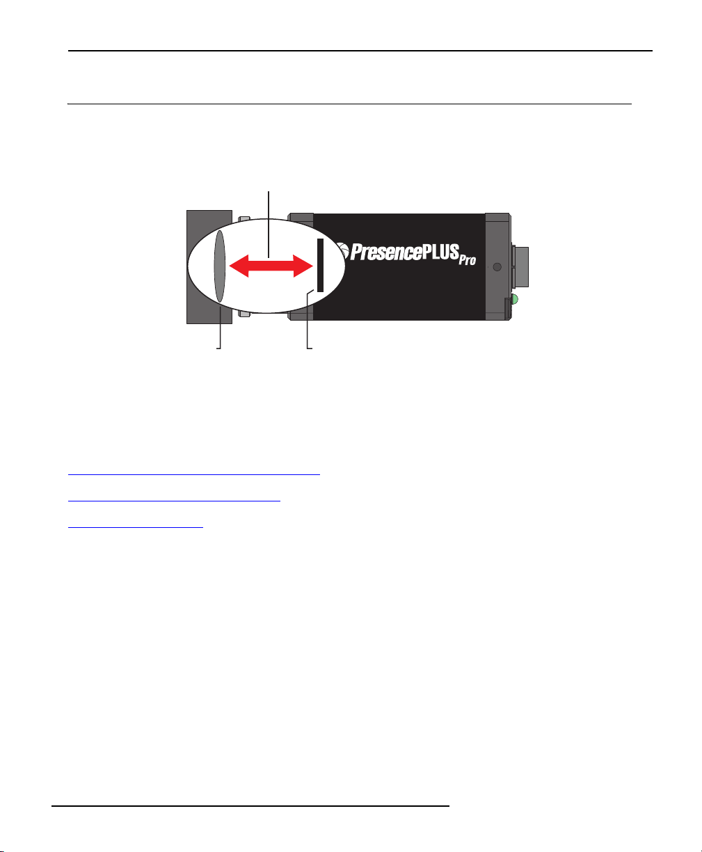
Determining Focal Length
Focal length is the distance between the rear nodal point of the lens (the point where the light
rays leave the rear of the lens) and the camera’s imager and is specified in millimeters.
Focal Length
Camera
Model PPCAM
Lens
Imager
-----------------------------------------------------------------------
Focal Length Tools
To choose the best focal length for a specific application, use any of the following tools:
Focal Length and Lens Extension Tables
Working Distance vs. FOV Graphs
Focal Length Formula
. . . . . . . . . . . . . . . . . . . . . . . . . . . . . . . . . . . . . . . . page 16
. . . . . . . . . . . . . . . . . . . . . . . . . . page 6
. . . . . . . . . . . . . . . . . . . . . . . . . . . . . . page 10
4 P/N 69950 rev. B
Banner Engineering Corp.
www.bannerengineering.com • Tel: 763.544.3164
•
Minneapolis, MN
•
USA
Page 8
Lens Selection Guide
Focal Length Considerations
If more than one focal length seems appropriate for the application, consider the following:
• Cost: A lens with a shorter focal length is less expensive.
• Depth of focus capability: Depth of focus (focus tolerance) is the area in front of and beyond
the optimal point of focus in which the image quality remains acceptable. A longer focal
length provides less depth of focus; a shorter focal length provides more depth of focus.
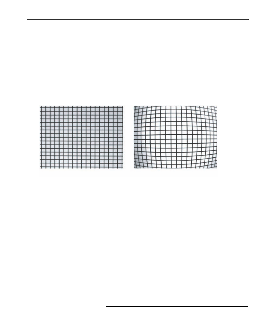
• Distortion (see example below): A larger focal length lens provides a less distorted image.
Gauging and the pattern matching tools are sensitive to distortion.
Image of Grid with 25 mm Lens
Banner Engineering Corp.
www.bannerengineering.com • Tel: 763.544.3164
•
Minneapolis, MN
•
USA
Image of Same Grid with 4 mm Lens
P/N 69950 rev. B 5P/N 69950 rev. B 5
Page 9

Lens Selection Guide
Focal Length and Lens Extension Tables
NOTE: Working distance and FOV must be known in order to use these tables.
See Field of View
Focal Length Table, Working Distances in Inches
on page 1 and Determining Working Distance on page 3.
FOV in
Inches
(H x V)
0.2 x 0.2 4.1* 5*
0.3 x 0.2 1.6* 5.2* 7*
0.4 x 0.3 2.1* 6.2* 8*
0.5 x 0.4 1.7 2.6* 7.3* 9*
1.0 x 0.8 2.5 3.3 5.2* 12.5* 17*
1.5 x 1.1 2.5 3.8 5.0 7.8* 17.7* 26*
2.0 x 1.5 3.3 5.0 6.7 10.4* 23* 34*
2.5 x 1.9 4.2 6.3 8.3 13.0* 28* 40*
3.0 x 2.3 5.0 7.5 10.0 15.6* 33 46
3.5 x 2.6 2.9* 5.8 8.8 11.7 18.2* 39 54
4.0 x 3.0 3.3* 6.7 10.0 13.3 21* 44 62
4.5 x 3.4 3.8* 7.5 11.3 15.0 23 49 70
5.0 x 3.8 4.2* 8.3 12.5 16.7 26 54 77
5.5 x 4.1 4.6* 9.2 13.8 18.3 29 59 85
6.0 x 4.5 5.0* 10.0 15.0 20 31 65 93
6.5 x 4.9 5.4* 10.8 16.3 22 34 70 101
7.0 x 5.3 5.8* 11.7 17.5 23 36 75 108
7.5 x 5.6 6.3 12.5 18.8 25 39 80 116
8.0 x 6.0 6.7 13.3 20 27 42 85 124
8.5 x 6.4 7.1 14.2 21 28 44 91 121
9.0 x 6.8 7.5 15.0 23 30 47 96 139
9.5 x 7.1 7.9 15.8 24 32 49 101 147
10.0 x 7.5 8.3 16.7 25 33 52 106 155
10.5 x 7.9 8.8 17.5 26 35 55 111 162
11.0 x 8.3 9.2 18.3 28 37 57 117 170
11.5 x 8.6 9.6 19.2 29 38 60 122 178
12.0 x 9.0 10.0 20 30 40 63 127 186
12.5 x 9.4 10.4 21 31 42 65 132 193
13.0 x 9.8 10.8 22 33 43 68 147 201
13.5 x 10.1 11.3 23 34 45 70 143 209
14.0 x 10.5 11.7 23 35 47 73 148 216
14.5 x 10.9 12.1 24 36 48 76 153 224
15.0 x 11.3 12.5 25 38 50 78 158 232
15.5 x 11.6 12.9 26 39 52 81 164 240
16.0 x 12.0 13.3 27 40 53 83 169 247
16.5 x 12.4 13.8 28 41 55 86 174 255
17.0 x 12.8 14.2 28 43 57 89 179 263
17.5 x 13.1 14.6 29 44 58 91 184 271
18.0 x 13.5 15.0 30 45 60 94 190 278
18.5 x 13.9 15.4 31 46 62 96 195 286
19.0 x 14.3 15.8 32 48 63 99 200 294
19.5 x 14.6 16.3 33 49 65 102 205 302
20.0 x 15.0 16.7 33 50 67 104 210 309
4 mm
Lens
8 mm
Lens
Working Distances in Inches
12 mm
Lens
16 mm
Lens
25 mm
Lens
50 mm
Lens
Banner Engineering Corp.
www.bannerengineering.com • Tel: 763.544.3164
6 P/N 69950 rev. B
75 mm
Lens
Extensions
may be
added to
these 25- ,
50- ,and
75-mm
lenses as
indicated by
the given
lengths
(in mm) in the
inch table
•
Minneapolis, MN
*
.
•
USA
Page 10

Lens Selection Guide
Lens Extensions Table, Working Distances in Inches
inch table
These extensions, in lengths of 0.5, 1.0, 5.0, 10, and 20 millimeters, may be combined to
achieve a desired focal length. Extension lengths are in parenthesis.
FOV in Inches
(horizontal x vertical)
0.2 x 0.2 4.1 (40) 5 (40)
0.3 x 0.2 1.6 (10) 5.2 (30) 7 (30)
0.4 x 0.3 2.1 (10) 6.2 (20) 8 (20)
0.5 x 0.4 2.6 (7) 7.3 (15) 9 (15)
1.0 x 0.8 5.2 (5) 12.5 (10) 17 (10)
1.5 x 1.1 7.8 (1) 17.7 (5) 26 (10)
2.0 x 1.5 10.4 (1) 23 (1) 34 (5)
2.5 x 1.9 13.0 (1) 28 (1) 40 (5)
3.0 x 2.3 15.6 (1)
3.5 x 2.6 2.9 (0.5) 18.2 (1)
4.0 x 3.0 3.3 (0.5) 21 (1)
4.5 x 3.4 3.8 (0.5)
5.0 x 3.8 4.2 (0.5)
5.5 x 4.1 4.6 (0.5)
6.0 x 4.5 5.0 (0.5)
6.5 x 4.9 5.4 (0.5)
7.0 x 5.3 5.8 (0.5)
7.5 x 5.6 6.3
8.0 x 6.0 6.7
8.5 x 6.4 7.1
9.0 x 6.8 7.5
9.5 x 7.1 7.9
10.0 x 7.5 8.3
10.5 x 7.9 8.8
11.0 x 8.3 9.2
11.5 x 8.6 9.6
12.0 x 9.0 10.0
12.5 x 9.4 10.4
13.0 x 9.8 10.8
13.5 x 10.1 11.3
14.0 x 10.5 11.7
14.5 x 10.9 12.1
15.0 x 11.3 12.5
15.5 x 11.6 12.9
16.0 x 12.0 13.3
16.5 x 12.4 13.8
17.0 x 12.8 14.2
17.5 x 13.1 14.6
18.0 x 13.5 15.0
18.5 x 13.9 15.4
19.0 x 14.3 15.8
19.5 x 14.6 16.3
20.0 x 15.0 16.7
Working Distances in Inches
4 mm
Lens
25 mm
Lens
50 mm
Lens
75 mm
Lens
Banner Engineering Corp.
•
Minneapolis, MN
•
USA
www.bannerengineering.com • Tel: 763.544.3164
P/N 69950 rev. B 7P/N 69950 rev. B 7
Page 11

Lens Selection Guide
Focal Length Table, Working Distances in Millimeters
FOV in
Millimeters
(H x V)
5 x 4 104* 115*
10 x 8 156* 230*
15 x 11 78* 208* 285*
20 x 15 104* 260* 370*
25 x 19 83 130* 313* 425*
30 x 23 75 100 156* 365* 510*
35 x 26 58 88 117 182* 417* 595*
40 x 30 67 100 133 208* 469* 640*
45 x 34 75 113 150 234* 521 696
50 x 38 83 125 167 260* 573 773
60 x 45 50* 100 150 200 313* 677 928
70 x 53 58* 117 175 233 365* 781 1082
80 x 60 67* 133 200 267 417 885 1237
90 x 68 75* 150 225 300 469 990 1392
100 x 75 83* 167 250 333 521 1094 1546
110 x 83 92* 183 275 367 573 1198 1701
120 x 90 100* 200 300 400 625 1302 1856
130 x 98 108 217 325 433 677 1406 2010
140 x 105 117 233 350 467 729 1510 2165
150 x 113 125 250 375 500 781 1615 2320
160 x 120 133 267 400 533 833 1719 2474
170 x 128 142 283 425 567 885 1823 2629
180 x 135 150 300 450 600 938 1927 2783
190 x 143 458 317 475 633 990 2031 2938
200 x 150 167 333 500 667 1042 2135 3093
225 x 169 188 375 563 750 1172 2396 3479
250 x 188 208 417 625 833 1302 2656 3866
275 x 206 229 458 688 917 1432 2917 4253
300 x 225 250 500 750 1000 1563 3177 4639
325 x 244 271 542 813 1083 1693 3438 5026
350 x 263 292 583 875 1167 1823 3698 5412
375 x 281 313 625 938 1250 1953 3958 5799
400 x 300 333 667 1000 1333 2083 4219 6186
425 x 319 354 708 1063 1417 2214 4479 6572
450 x 338 375 750 1125 1500 2344 4740 6959
475 x 356 396 792 1188 1583 2474 5000 7345
500 x 375 417 833 1250 1667 2604 5260 7732
525 x 394 438 875 1313 1750 2734 5521 8119
550 x 413 458 917 1375 1833 2865 5781 8505
575 x 431 479 958 1438 1917 2995 6042 8892
600 x 450 500 1 000 1500 2000 3125 6302 9278
625 x 469 521 1 042 1563 2083 3255 6563 9665
650 x 488 542 1 083 1625 2167 3385 6823 10051
4 mm
Lens
Working Distances in Millimeters
8 mm
Lens
12 mm
Lens
16 mm
Lens
25 mm
Lens
50 mm
Lens
75 mm
Lens
*
Extensions
may be
added to
these 25- ,
50- ,and
75-mm
lenses as
indicated by
the given
lengths
(in mm) in the
mm table
.
8 P/N 69950 rev. B
Banner Engineering Corp.
•
Minneapolis, MN
•
USA
www.bannerengineering.com • Tel: 763.544.3164
Page 12

Lens Selection Guide
Lens Extensions Table, Working Distances in Millimeters
mm table
These extensions, in lengths of 0.5, 1.0, 5.0, 10, and 20 millimeters, may be combined to
achieve a desired focal length. Extension lengths are in parenthesis.
FOV in Millimeters
(horizontal x vertical)
5 x 4 104 (40) 115 (40)
10 x 8 156 (30) 230 (30)
15 x 11 78 (10) 208 (20) 285 (20)
20 x 15 104 (10) 260 (15) 370 (15)
25 x 19 130 (7) 313 (10) 425 (10)
30 x 23 156 (5) 365 (5) 510 (10)
35 x 26 182 (1) 417 (1) 595 (5)
40 x 30 208 (1) 469 (1) 640 (5)
45 x 34 234 (1)
50 x 38 260 (1)
60 x 45 50 (0.5) 313 (1)
70 x 53 58 (0.5) 365 (1)
80 x 60 67 (0.5)
90 x 68 75 (0.5)
100 x 75 83 (0.5)
110 x 83 92 (0.5)
120 x 90 100 (0.5)
130 x 98 108
140 x 105 117
150 x 113 125
160 x 120 133
170 x 128 142
180 x 135 150
190 x 143 458
200 x 150 167
225 x 169 188
250 x 188 208
275 x 206 229
300 x 225 250
325 x 244 271
350 x 263 292
375 x 281 313
400 x 300 333
425 x 319 354
450 x 338 375
475 x 356 396
500 x 375 417
525 x 394 438
Working Distances in Millimeters
4 mm
Lens
25 mm
Lens
50 mm
Lens
75 mm
Lens
Banner Engineering Corp.
•
Minneapolis, MN
•
USA
www.bannerengineering.com • Tel: 763.544.3164
P/N 69950 rev. B 9P/N 69950 rev. B 9
Page 13

Lens Selection Guide
Working Distance vs. FOV Graphs
The graphs in this section provide a visual comparison of FOV as a function of working distance
for lenses of the various focal lengths.
Note: Working distance and FOV must be known in order to use these graphs. See Field of
View on page 1 and Determining Working Distance on page 3.
Lens Model LCF04
mm (inches)
Field of View
750 (30")
700 (28")
650 (26")
600 (24")
550 (22")
500 (20")
450 (18")
400 (16")
350 (14")
300 (12")
250 (10")
200 (8")
150 (6")
100 (4")
50 (2")
0
050
(2")
100
(4")
150
(6")
200
(8")
250
(10")
300
(12")
350
(14")
400
(16")
450
(18")
500
(20")
550
(22")
Horizontal FOV
Vertical FOV
600
mm
(24")
(inches)
10 P/N 69950 rev. B
Working Distance
Working Distance vs. FOV, 4 mm Lens
Banner Engineering Corp.
www.bannerengineering.com • Tel: 763.544.3164
•
Minneapolis, MN
•
USA
Page 14

Lens Selection Guide
mm (inches)
400 (16")
350 (14")
300 (12")
250 (10")
200 (8")
150 (6")
Field of View
100 (4")
50 (2")
mm (inches)
400 (16")
350 (14")
300 (12")
250 (10")
200 (8")
150 (6")
Field of View
100 (4")
50 (2")
0
050
0
050
(2")
(2")
Lens Models LCF08, LCF08LT
100
150
200
250
300
350
(4")
(6")
(8")
(10")
(12")
(14")
400
(16")
Working Distance
Working Distance vs. FOV, 8 mm Lens
Lens Models LCF12, LCF12T
100
150
200
250
300
350
(4")
(6")
(8")
(10")
(12")
(14")
400
(16")
Working Distance
450
(18")
450
(18")
500
(20")
500
(20")
550
(22")
550
(22")
Horizontal FOV
Vertical FOV
600
mm
(24")
(inches)
Horizontal FOV
Vertical FOV
600
mm
(24")
(inches)
Working Distance vs. FOV, 12 mm Lens
Banner Engineering Corp.
www.bannerengineering.com • Tel: 763.544.3164
•
Minneapolis, MN
•
USA
P/N 69950 rev.P/N 69950 rev. B 11
Page 15

Lens Selection Guide
mm (inches)
400 (16")
350 (14")
300 (12")
250 (10")
200 (8")
150 (6")
Field of View
100 (4")
50 (2")
0
050
(2")
Lens Models LCF16, LCF16LT
100
150
200
250
300
350
400
(4")
(6")
(8")
(10")
(12")
(14")
(16")
450
(18")
Working Distance
Working Distance vs. FOV, 16 mm Lens
500
(20")
550
(22")
Horizontal FOV
Vertical FOV
600
mm
(24")
(inches)
12 P/N 69950 rev. B
Banner Engineering Corp.
www.bannerengineering.com • Tel: 763.544.3164
•
Minneapolis, MN
•
USA
Page 16

Lens Models LCF25R, LCF25LR, LCF25LT
Lens Selection Guide
100 (4.0)
90 (3.6)
80 (3.2)
70 (2.8)
60 (2.4)
50 (2.0)
40 (1.6)
30 (1.2)
20 (0.8)
Field of View, mm (inches)
10 (0.4)
0
0
Horizontal FO
1 mm Spacer
5 mm Spacer
10 mm Spacer
20 mm Spacer
50
(2)
100
(4)
150
(6)
200
(8)
250
(10)
300
(12)
350
(14)
400
(16)
Working Distance, mm (inches)
Working Distance vs. FOV, 25 mm Lens with Spacers
V
Vertical FOV
450
(18)
500
(20)
Banner Engineering Corp.
www.bannerengineering.com • Tel: 763.544.3164
•
Minneapolis, MN
•
USA
P/N 69950 rev.P/N 69950 rev. B 13
Page 17

Lens Selection Guide
500
(20)
400
(16)
Lens Models LCF50L1R, LCF50L2R, LCF50LT
zontal FOV
i
Hor
300
(12)
200
(8)
See expanded view
on following graph.
Field of View, mm (inches)
100
(4)
0
0
Vertical FOV
No Spacers
1 mm Spacer
1000
(40)
2000
(80)
3000
(120)
4000
(160)
Working Distance, mm (inches)
Working Distance vs. FOV, 50 mm Lens with Spacers
(Showing Working Distance up to 5000 mm [200 inches])
5000
(200)
14 P/N 69950 rev. B
Banner Engineering Corp.
www.bannerengineering.com • Tel: 763.544.3164
•
Minneapolis, MN
•
USA
Page 18

50
(2.0)
Lens Selection Guide
This graph is an expanded view of the points
nearest the origin (0,0) in the previous graph.
FOV
40
(1.6)
30
(1.2)
20
(0.8)
10
(0.4)
Field of View, mm (inches)
0
0
Working Distance vs. FOV, 50 mm Lens with Spacers
(Showing Working Distance up to 700 mm [28 inches])
40 mm Spacer
100
(4)
Horizontal
ical FOV
Vert
5 mm Spacer
10 mm Spacer
20 mm Spacer
200
(8)
300
(12)
400
(16)
500
(20)
Working Distance, mm (inches)
600
(24)
Banner Engineering Corp.
www.bannerengineering.com • Tel: 763.544.3164
•
Minneapolis, MN
•
USA
P/N 69950 rev.P/N 69950 rev. B 15
Page 19

Lens Selection Guide
Focal Length Formula
NOTE: Working distance and FOV must be known in order to use this formula. See Field of
View on page 1 and Determining Working Distance on page 3.
Focal Length =
Working Distance x Camera Imager Width (Height)
Horizontal (Vertical) FOV
PresencePLUS Pro Camera Imager Width = 4.8 mm.
PresencePLUS Pro Camera Imager Height = 3.6 mm.
For Vertical FOV, replace Camera Imager Width with Camera Imager Height.
Example:
What focal length is needed to view a 45-inch wide object from a distance of 200
inches?
200" x 4.8 mm
Focal Length =
= 21.25 mm
45"
The best option is to use a 25 mm lens.
16 P/N 69950 rev. B
Banner Engineering Corp.
www.bannerengineering.com • Tel: 763.544.3164
•
Minneapolis, MN
•
USA
Page 20

Lens Selection Guide
Lens Options Table
The table below lists available C-Mount lenses. Use the link listed under Manufacturers Lens
Specifications for dimensions and aperture information where applicable.
Description Model P/N
Standard C-Mount Lenses
4 mm LCF04 68884
8 mm, focus locking LCF08 57298
12 mm, focus locking LCF12 57299
16 mm, focus locking LCF16 56522
25 mm, plastic LCF25R 68885
25 mm, focus locking, iris locking, metal LCF25LR 68886
50 mm, focus locking, iris locking, plastic LCF50L1R 68887
50 mm, focus locking, iris locking, metal LCF50L2R 68888
75 mm, focus locking, iris locking, metal LCF75LR 70545
High-Performance C-Mount Lenses
6.5 mm, focus locking LCF06LT 70031
8 mm, focus locking LCF08LT 70032
12 mm, focus locking, iris locking LCF12LT 70033
16 mm, focus locking LCF16LT 70034
Manufacturer’s Lens Specifications
See 4- to 16-mm Lens Specifications on page 18.
See 4- to 16-mm Lens Specifications on page 18.
See 4- to 16-mm Lens Specifications on page 18.
See 4- to 16-mm Lens Specifications on page 18.
http://www.isorainbow.com/pdf/lens_specs/g25_g25m_
g50.pdf
http://www.isorainbow.com/specs/1_inch/g25.html
http://www.isorainbow.com/pdf/lens_specs/s50wi.pdf
http://www.isorainbow.com/specs/1_inch/g50.html
http://www.isorainbow.com/specs/1_inch/g75.html
http://www.tamron.com/cctv/23fm65.htm#specs
http://www.tamron.com/cctv/23fm08l.htm#specs
http://www.tamron.com/cctv/23fm12l.htm#specs
http://www.tamron.com/cctv/23fm16l.htm#specs
25 mm, focus locking LCF25LT 70035
50 mm, focus locking LCF50LT 70036
Lens Extension Kit
Lens Extension Kit LEK 69052
Banner Engineering Corp.
www.bannerengineering.com • Tel: 763.544.3164
•
Minneapolis, MN
•
USA
http://www.tamron.com/cctv/23fm25l.htm#specs
http://www.tamron.com/cctv/23fm50l.htm#specs
n/a
P/N 69950 rev.P/N 69950 rev. B 17
Page 21

Lens Selection Guide
NOTE: All dimensions are in millimeters except thread diameter, which is 1 inch for all lenses.
4- to 16-mm Lens Specifications
LCF04, 4 mm Lens
34
25
14
LCF12, 12 mm Lens
30.3
26
1 - 32 UNF
34
3 Locking Set Screws
LCF08, 8 mm Lens
30.3
20
4.5
LCF16, 16 mm Lens
34.3
26
1 - 32
UNF
33
34
3 Locking Set Screws
18 P/N 69950 rev. B
4.5
1 - 32
UNF
33
3 Locking Set Screws
34
4.5
Banner Engineering Corp.
www.bannerengineering.com • Tel: 763.544.3164
1 - 32 UNF
•
Minneapolis, MN
33
•
USA
Page 22

Index
Lens Selection Guide
F
field of view
determining 2
formula 2
focal length
determining 4
example 16
formula 16
tables 6
tools 4
L
lenses
12 mm 11
16 mm 12
25 mm with spacers 13
4 mm 10
50 mm with spacers 14
8 mm 11
general considerations i, 1
table of options 17
W
working distance 3
Banner Engineering Corp.
www.bannerengineering.com • Tel: 763.544.3164
•
Minneapolis, MN
•
USA
P/N 69950 rev. B 19
Page 23

Page 24

Banner Engineering Corp.
9714 Tenth Avenue North
Minneapolis, MN 55441
Phone: 763.544.3164
www.bannerengineering.com
Email: sensors@bannerengineering.com
WARRANTY: Banner Engineering Corp. warrants its products to be free from defects for one year. Banner Engineering Corp. will
repair or replace, free of charge, any product of its manufacture found to be defective at the time it is returned to the factory during
the warranty period. This warranty does not cover damage or liability for the improper application of Banner products. This warranty
is in lieu of any other warranty either expressed or implied.
P/N 69950 rev. B
 Loading...