

Page 1
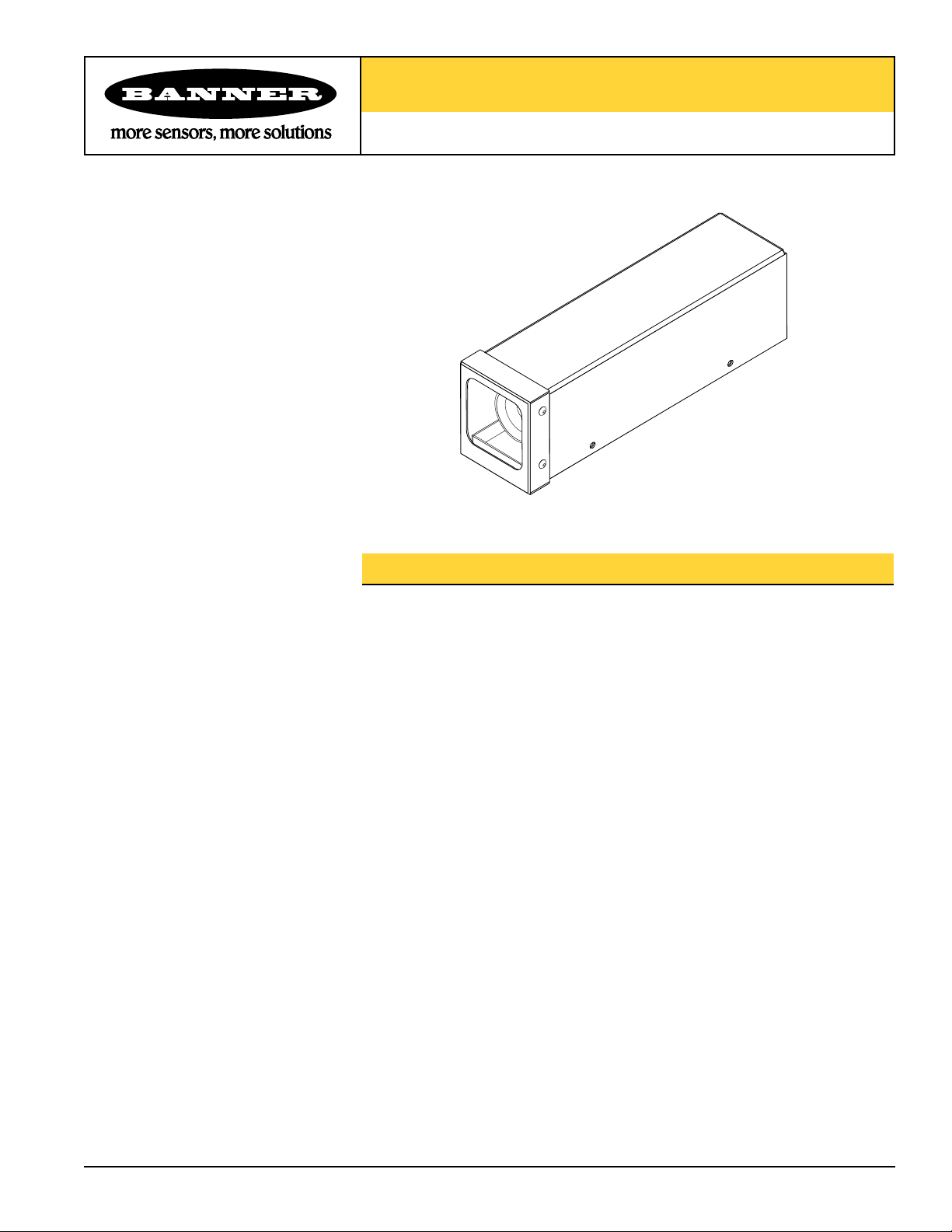
Model PPE-G/PPE-P Enclosure Kit
®
Dust-Resistant Enclosure for PresencePLUS® Pro Vision System Camera w/o Light
Features
• Small size encloses PresencePLUS Pro camera and lens only, when ring light is not
required
• Protects camera from damage caused by accidental bumps and scratches
• Helps maintain lens focus by enclosing the lens and camera
• Keeps dust and dirt off camera and lens in applications not requiring washdown
and/or aggressive corrosion protection
• Glass or polycarbonate window models available (see Specifications)
• Can be mounted directly through base plate, or with optional flat or right-angle
mounting bracket
• Allows fine adjustment for aiming camera up and down, and from side to side
Printed in USA 01/04 P/N 115342 rev. A
Page 2
Model PPE-G/PPE-P Enclosure Kit
Model PPE-G/PPE-P Enclosure Kit
P/N 115342 rev. A 3
Banner Engineering Corp. • Minneapolis, MN U.S.A.
www.bannerengineering.com • Tel: 763.544.3164
Installation
Remove Enclosure Housing from Base
NOTE: It is not necessary to remove the end cap and window to install the camera.
1. Remove five screws from around base of housing using a #2 Phillips head
screwdriver.
2. Lift back of housing up off the base, slide housing forward until it clears the front
end cap, and separate the housing from the base.
Install the PresencePLUS Pro Camera
1. Verify that the lens is mounted on the camera.
2. Check the fit of the camera/lens assembly. The lens should be positioned about
flush with the base’s front edge. When using lenses of greater than 25 mm focal
length, remove the camera bracket and mount it in reverse position so the camera
can be moved further back.
3. Mount the camera on the camera bracket, using the four supplied M3x6 socket head
screws, lock washers and flat washers. Tighten the camera screws with the included
2.5 mm hex wrench.
4. Slide the camera and bracket so the front of the lens is approximately flush with the
front of the base, and tighten the two bracket screws on the bottom of the base.
Mounting the Enclosure Base – Without the Optional Mounting Bracket
1. Drill four holes for #8 screws into the mounting surface. Use the base as a template
or see the dimension drawing on page 4. (Mounting holes may be clearance drilled
or tapped.)
2. Mount the base using four #8 screws of sufficient length (user-supplied).
Mounting the Enclosure Base – Using the Optional Mounting Bracket
1. Assemble the bracket to the enclosure base (to either side of the enclosure), using
the hardware supplied with the bracket.
2. Drill two holes for " screws into the mounting surface. Use the bracket as a
template. (Mounting holes may be drilled or tapped.)
3. Mount the base using two " screws of sufficient length (user-supplied).
For Applications with Vibration
If the Right-Angle Bracket is to be used
to mount the enclosure in a vibration
application, the optional Front Bracket
(SMBPPEF) is required. Use it to stabilize
the front of the enclosure after it is
mounted, aimed, and assembled.
1. The Front Bracket fastens to the PEM nut
on the bottom of the enclosure, using the
#10 screw and washers supplied with the
bracket. Remove the clear dust seal over
the PEM nut first.
2. To mount the side of the bracket to the
mounting surface, use the bracket as a
template to mark the hole location. Drill
a hole for a " screw in the mounting
surface.
3. The slots in the Front Bracket allow some
additional adjustment after mounting, if
needed.
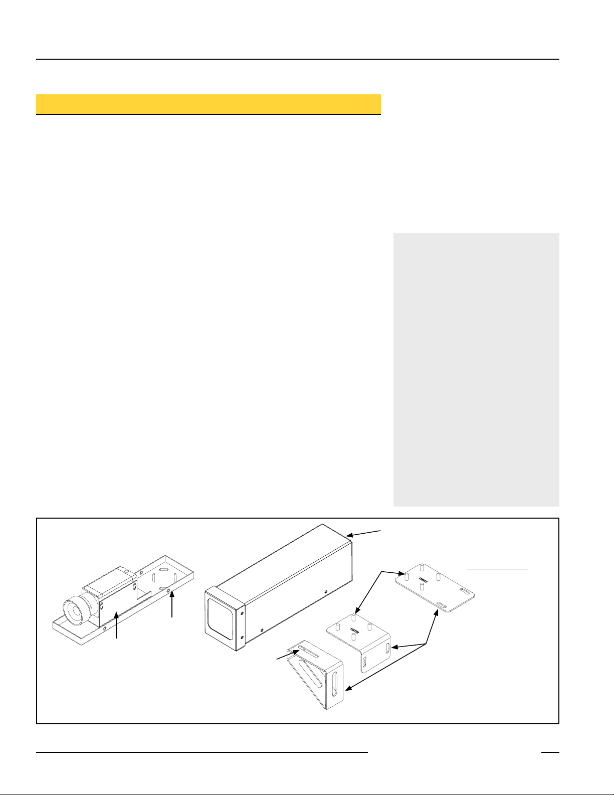
Enclosure Housing
washers and nuts
included
Enclosure Base
Camera Bracket
screw and washer
included
Model SMBPPEF
Front Bracket for Vibration Applications
Figure 1. Assembling the enclosure
2 P/N 115342 rev. A
Banner Engineering Corp. • Minneapolis, MN U.S.A.
www.bannerengineering.com • Tel: 763.544.3164
Clearance for " screws
Model SMBPPEA
Right-Angle Bracket
Optional Enclosure
Mounting Brackets
Model SMBPPES
Flat Bracket
Page 3

Model PPE-G/PPE-P Enclosure Kit
Connect the Camera
1. Push the camera cable’s round connector through the black grommet in the back of
the enclosure housing.
2. Connect the cable to the camera, but do not install the enclosure housing now.
3. Power up the camera.
4. Adjust horizontal aim using the mounting screws on the base (or straight bracket, if
used).
5. If right-angle bracket is not used, adjust vertical aim on the camera bracket.
If right-angle bracket is used, tighten screws in center of camera bracket slots and
use the vertical face of the right-angle bracket for adjustment.
6. Adjust the lens focus and aperture.
7. Verify that the front of the lens does not extend past the front edge of the base;
adjust camera bracket on base, if needed.
Assemble the Enclosure
1. Verify that there are no smudges on the window (especially on the inside) that could
cause imaging problems. (The window can be cleaned with standard glass cleaner
and a soft, non-abrasive cloth.)
2. Place the enclosure housing over the camera so the housing’s front end cap wraps
around the base’s front edge. Push the housing back until it clears the rear of the
base and drops down.
3. Reinstall the five screws.
Damaged Window Replacement
1. Remove the (4) Phillips screws on the sides of the end cap.
2. Remove the end cap with window and gasket.
3. Place the new window in the end cap and place gasket on top (it will be between the
window and the enclosure housing).
4. Place the end cap assembly onto housing and push down to compress gasket. Hold
down while reinserting (4) screws.
5. Tighten screws.
Specifications
Environmental Rating
Construction
NEMA 1, IEC IP40
Enclosure: 20 gauge cold rolled steel with clear zinc plate,
including edges
Screws and nuts: 18-8 stainless steel
Gasket: Cellular urethane foam
Window: Model PPE-G: Glass;
Model PPE-P: Polycarbonate
Cord Grommet: 6/6 Nylon and Buna/N Nitrile
Banner Engineering Corp. • Minneapolis, MN U.S.A.
P/N 115342 rev. A 3
www.bannerengineering.com • Tel: 763.544.3164
Page 4

Model PPE-G/PPE-P Enclosure Kit
®
L
61.7 mm
(2.43")
207.5 mm
(8.17")
55.4 mm
(2.18")
2 x 4.47 mm (0.18")
Wide Slots
28.7 mm
(1.13")
131.4 mm
(5.17")
28.7 mm
(1.13")
14.7 mm
(0.58")
12 mm
(0.47")
C
Dimensions
WARRANTY: Banner Engineering Corp. warrants its products to be free from defects for one year. Banner Engineering Corp. will repair
or replace, free of charge, any product of its manufacture found to be defective at the time it is returned to the factory during the warranty
period. This warranty does not cover damage or liability for the improper application of Banner products. This warranty is in lieu of any
other warranty either expressed or implied.
P/N 115342 rev. A
Banner Engineering Corp., 9714 Tenth Ave. No., Minneapolis, MN USA 55441 • Phone: 763.544.3164 • www.bannerengineering.com • Email: sensors@bannerengineering.com
 Loading...