

Page 1
P
POLAR RETRO
1
10
100
1.0 m
3.3 ft
10 m
33 ft
100 m
330 ft
0.1 m
0.33 ft
1000
E
X
C
E
S
S
G
A
I
N
DISTANCE
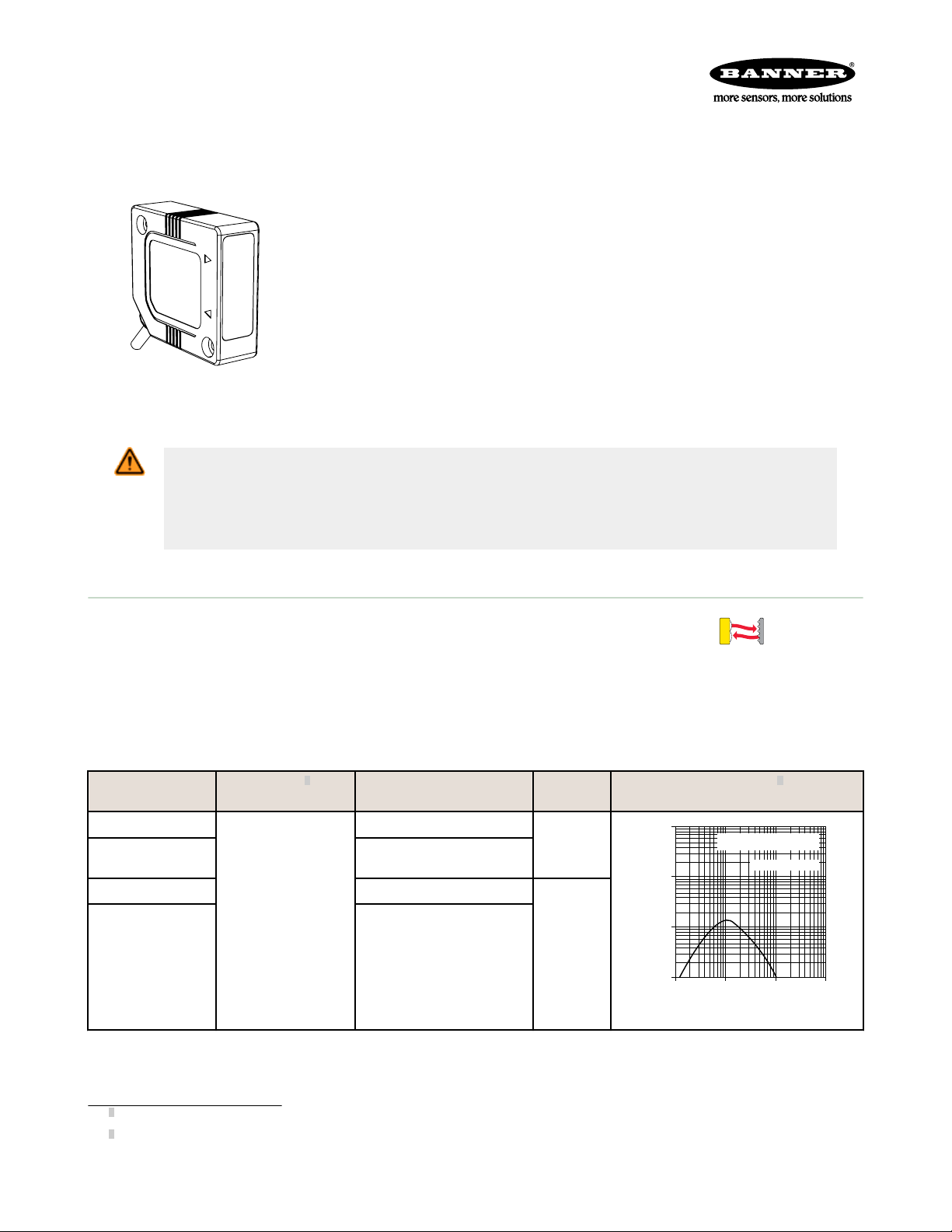
Retroreflective PicoDot
with BRT-51X51BM
PD49 Series Ruggedized PicoDot
Datasheet
• Environmentally sealed housing is only slightly larger than standard PD45
models, with all the functionality. Rated IEC IP67; NEMA 6
• Class 2 laser diode light source
• Convergent beam models have precise, high-energy sensing spot at focus,
available in four focal lengths: 50 mm (2 in), 100 mm (4 in), 200 mm (8 in),
and 300 mm (12 in)
• Retroreflective models have precise, narrow beam; excellent for sensing the
presence of tiny parts at close range, small parts at medium ranges, and for
accurate sensing over long distances
• Fast, 0.2 millisecond sensing response for high-speed sensing or counting
• 10 to 30 V dc operation; choice of NPN or PNP complementary solid state output
• Choose models with 2 m (6.5 ft) or 9 m (30 ft) unterminated cable, or with 150
mm (6 in) Euro-style pigtail quick-disconnect (QD) connector
WARNING: Not To Be Used for Personnel Protection
Never use this device as a sensing device for personnel protection. Doing so could lead to
serious injury or death. This device does not include the self-checking redundant circuitry necessary
to allow its use in personnel safety applications. A sensor failure or malfunction can cause either an
energized or de-energized sensor output condition.
®
Retroreflective-Mode Models
Excellent for applications where high sensing power and small beam size are
important. Operates over sensing ranges typically accomplished only by
conventional opposed-mode photoelectrics; uses a special filter to polarize the
emitted light, filtering out unwanted reflections from shiny objects.
To order 9 m (30 ft) cables, add “W/30” to the model number of any cabled
sensor (e.g., PD49VN6LLP W/30). Models with QD connectors require a mating
cable.
Models Range
1
Cable Output
Type
PD49VN6LLP
PD49VN6LLPQ
2 m (6.5 ft) cable
5-pin QD 150 mm (6 in)
pigtail
NPN
PD49VP6LLP 2 m (6.5 ft) cable
0.2 to 10.6 m (8 in
to 35 ft)
PD49VP6LLPQ
1
Tested using a BRT-51x51BM retro target (included with each sensor). Actual range depends on the efficiency and size of the retroreflective target used.
Some targets have produced ranges up to 39.6 m (130 ft).
2
Performance based on BRT-51X51BM retroreflective target
P/N 67450 Rev. B 20 December 2013
5-pin QD 150 mm (6 in)
pigtail
PNP
Visible Red; Class 2 laser; 650 nm
Excess Gain
2
Page 2
CONVERGENT
1
10
100
10 mm
0.4 in.
100 mm
4 in.
1000 mm
40 in.
1 mm
0.04 in.
1000
DISTANCE
50mm (2 in.) PicoDot
Convergent Mode
EXCESS GAIN
62.5 mm
2.5 in
50 mm
2.0 in
37.5 mm
1.5 in
25 mm
1.0 in
12.5 mm
0.5 in
0
0
1 mm
2 mm
3 mm
1 mm
2 mm
3 mm
0
0.04 in
0.08 in
0.12 in
0.04 in
0.08 in
0.12 in
DISTANCE
50 mm (2 in) PicoDot
Convergent Mode
1
10
100
10 mm
0.4 in.
100 mm
4 in.
1000 mm
40 in.
1 mm
0.04 in.
1000
DISTANCE
100 mm (4 in.) PicoDot
Convergent Mode
EXCESS GAIN
125 mm
5.0 in
100 mm
4.0 in
75 mm
3.0 in
50 mm
2.0 in
25 mm
1.0 in
0
0
1 mm
2 mm
3 mm
1 mm
2 mm
3 mm
0
0.04 in
0.08 in
0.12 in
0.04 in
0.08 in
0.12 in
DISTANCE
100 mm (4 in) PicoDot
Convergent Mode
1
10
100
10 mm
0.4 in.
100 mm
4 in.
1000 mm
40 in.
1 mm
0.04 in.
1000
DISTANCE
200 mm (8 in.) PicoDot
Convergent Mode
EXCESS GAIN
250 mm
10.0 in
200 mm
8.0 in
150 mm
6.0 in
100 mm
4.0 in
50 mm
2.0 in
0
0
1 mm
2 mm
3 mm
1 mm
2 mm
3 mm
0
0.04 in
0.08 in
0.12 in
0.04 in
0.08 in
0.12 in
DISTANCE
200 mm (8 in) PicoDot
Convergent Mode
PD49 Series Ruggedized PicoDot
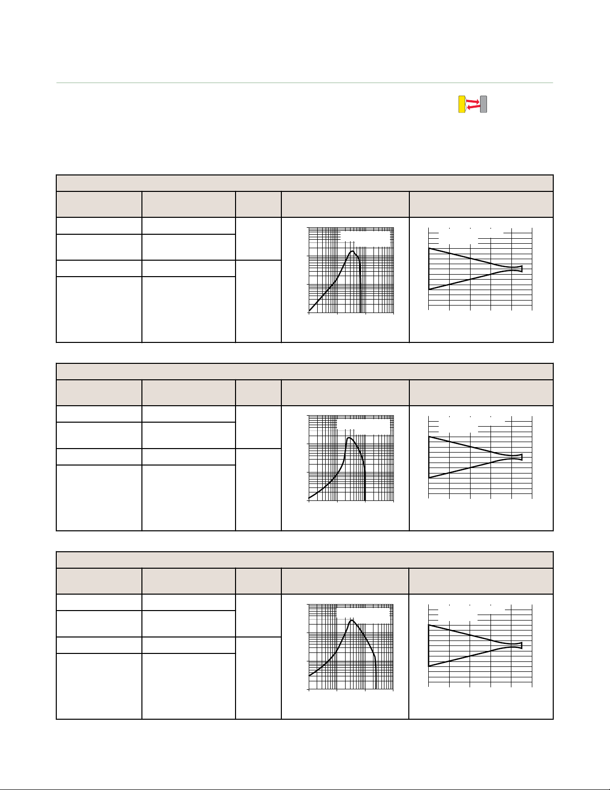
Convergent-Mode Models
Excels at sensing small parts and profiles and uses fixed-field technology to
ignore objects beyond the maximum sensing distance.
®
To order 9 m (30 ft) cables, add “W/30” to the model number of any cabled
sensor (e.g., PD49VN6C100 W/30). Models with QD connectors require a
mating cable.
50 mm (2 inch) Focus
Models Cable Output
Excess Gain Beam Width
Type
PD49VN6C50 2 m (6.5 ft) cable NPN
PD49VN6C50Q 5-pin Euro-style QD
150 mm (6 in) pigtail
PD49VP6C50 2 m (6.5 ft) cable PNP
PD49VP6C50Q 5-pin Euro-style QD
150 mm (6 in) pigtail
102 mm (4 inch) Focus
Models Cable Output
Excess Gain Beam Width
Type
PD49VN6C100 2 m (6.5 ft) cable NPN
PD49VN6C100Q 5-pin Euro-style QD
150 mm (6 in) pigtail
PD49VP6C100 2 m (6.5 ft) cable PNP
PD49VP6C100Q 5-pin Euro-style QD
150 mm (6 in) pigtail
Visible Red; Class 2 laser; 650 nm
203 mm (8 inch) Focus
Models Cable Output
Excess Gain Beam Width
Type
PD49VN6C200 2 m (6.5 ft) cable NPN
PD49VN6C200Q 5-pin Euro-style QD
150 mm (6 in) pigtail
PD49VP6C200 2 m (6.5 ft) cable PNP
PD49VP6C200Q 5-pin Euro-style QD
150 mm (6 in) pigtail
2 www.bannerengineering.com - tel: 763-544-3164 P/N 67450 Rev. B
Page 3
1
10
100
10 mm
0.4 in.
100 mm
4 in.
1000 mm
40 in.
1 mm
0.04 in.
1000
DISTANCE
300 mm (12 in.) PicoDot
Convergent Mode
EXCESS GAIN
375 mm
14.0 in
300 mm
12.0 in
225 mm
8.0 in
150 mm
6.0 in
75 mm
3.0 in
0
0
1 mm
2 mm
3 mm
1 mm
2 mm
3 mm
0
0.04 in
0.08 in
0.12 in
0.04 in
0.08 in
0.12 in
DISTANCE
300 mm (12 in) PicoDot
Convergent Mode
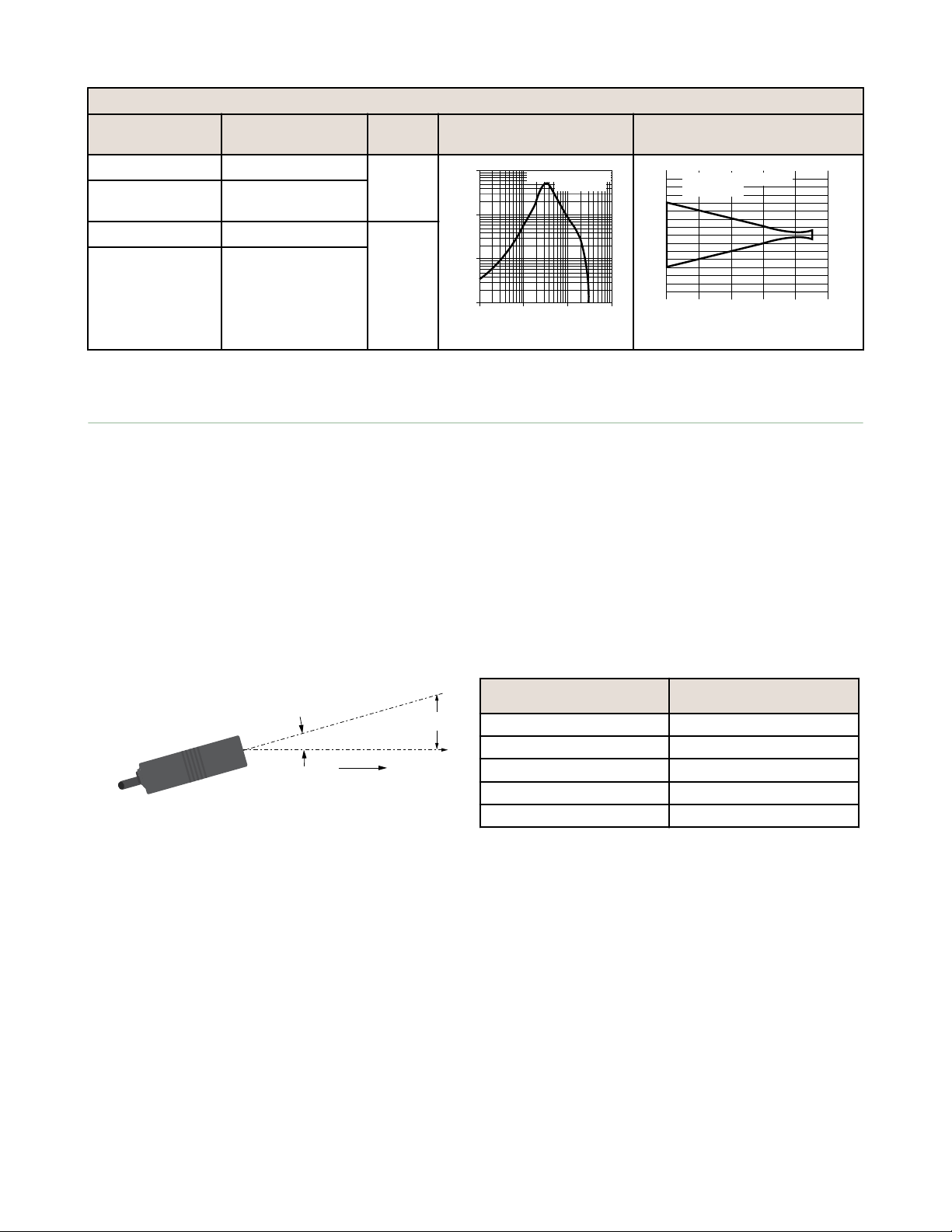
Ø = Misalignment Angle
Y = X(tan Ø)
X
Laser
Emitter
Y
Ø
PD49 Series Ruggedized PicoDot
®
305 mm (12 inch) Focus
Models Cable Output
Excess Gain Beam Width
Type
PD49VN6C300 2 m (6.5 ft) cable NPN
PD49VN6C300Q 5-pin Euro-style QD
150 mm (6 in) pigtail
PD49VP6C300 2 m (6.5 ft) cable PNP
PD49VP6C300Q 5-pin Euro-style QD
150 mm (6 in) pigtail
Retroreflective Sensor Alignment
Because the PicoDot laser sensor has such a long sensing range, and because its beam is so narrow (compared to the
beam of typical retro sensors), its alignment is somewhat less forgiving and more difficult to accomplish. As indicated, the
effect of angular misalignment can be dramatic, especially over distance. For example, with one 51 mm (2 in) reflective
target mounted at a distance of 6 m (20 ft) from the sensor, only one degree of angular misalignment will cause the
center of the laser beam to miss the center of the target by 102 mm (4 in), and miss the target altogether by almost 76
mm (3 in).
Alignment tip: When using a small retroreflective target at medium or long range, it is often useful to temporarily attach
(or suspend) a strip of retroreflective tape (such as BRT-THG-2-100) along a line that intersects the real target. The visible
red laser beam is easily seen in normal room lighting; sight along the beam toward the target, from behind the sensor.
Move the sensor to scan the laser beam back and forth across the tape strip, to guide the beam onto the target.
The use of mounting bracket SMB-46A may simplify alignment, because of its precision-positioning feature. After mounting
the bracket and the sensor, tighten the screws in the two corners of the bracket to position the beam in the exact spot
needed.
Figure 1. Beam displacement per degree of misalignment
Distance (X) To Retro Target Beam Displacement (Y) for 1°
1.5 m (5 ft) 25 mm (1 in)
3 m (10 ft) 50 mm (2 in)
6 m (20 ft) 100 mm (4 in)
15 m (50 ft) 250 mm (10 in)
30 m (100 ft) 500 mm (20 in)
of Misalignment
P/N 67450 Rev. B www.bannerengineering.com - tel: 763-544-3164 3
Page 4

LASER LIGHT
DO NOT STARE INTO BEAM
CLASS 2 LASER PRODUCT
Avoid exposure - laser light
emitted from this aperture
PEAK POWER 2 mW
20KHz 10% DUTY CYCLE
660 - 680 nm
COMPLIES TO 21 CFR PART
1040.10 AND EN60825-1:1994
Sensing Distance = X
Approx.
0.5 m rad = 0.029º
Approx. 2 mm
W = 2 mm + 2X(tan 0.029º) = 2 mm + X(0.001)
W
Laser Emitter
LASER LIGHT
DO NOT STARE INTO BEAM
CLASS 2 LASER PRODUCT
Avoid exposure - laser light
emitted from this aperture
PEAK POWER 2 mW
20KHz 10% DUTY CYCLE
660 - 680 nm
COMPLIES TO 21 CFR PART
1040.10 AND EN60825-1:1994
Y
Beam divergence
approximately 1 milliradian
X
Beam size and shape
at aperture
LASER LIGHT
DO NOT STARE INTO BEAM
CLASS 2 LASER PRODUCT
Avoid exposure - laser light
emitted from this aperture
PEAK POWER 2 mW
20KHz 10% DUTY CYCLE
660 - 680 nm
COMPLIES TO 21 CFR PART
1040.10 AND EN60825-1:1994
PD49 Series Ruggedized PicoDot
Retroreflective Sensor Beam Size
Unlike conventional retroreflective sensors, the
retroreflective laser has the ability to sense relatively small
profiles. The figures demonstrate the diameter of the
smallest opaque rod that reliably breaks the laser beam at
several sensor-to-object distances. These values assume an
excess gain of about 10×. Flooding effects are possible
when the gain is much higher (reduce sensor gain in this
situation in order to reliably detect minimum object sizes).
Note the shape of the beam is elliptical and its size
increases as the distance from the sensor increases.
Minimum object detection sizes are dependent on both the
object’s distance from the sensor, and the direction (with
respect to the beam’s X and Y axes) in which the object
crosses the beam.
®
Figure 2. Beam divergence at 25ºC (beam size vs. distance)
Distance from
Sensor to Object
0.3 m (1 ft) 1.78 mm (0.07 in) 3.30 mm (0.13 in)
1.5 m (5 ft) 2.03 mm (0.08 in) 4.06 mm (0.16 in)
3 m (10 ft) 3.05 mm (0.12 in) 5.08 mm (0.20 in)
9 m (30 ft) 5.08 mm (0.20 in) 8.13 mm (0.32 in)
15 m (50 ft) 9.65 mm (0.38 in) 12.7 mm (0.50 in)
18 m (60 ft) 12.7 mm (0.50 in) 19.05 mm (0.75 in)
Figure 3. Minimum object detection size vs. distance
Installation Notes - Class 2 Laser Safety Notes
Low-power lasers are, by definition, incapable of causing eye injury within the duration
of a blink (aversion response) of 0.25 seconds. They also must emit only visible
wavelengths (400 to 700 nm). Therefore, an ocular hazard may exist only if individuals
overcome their natural aversion to bright light and stare directly into the laser beam.
• Do not stare at the laser.
• Do not point the laser at a person’s eye.
• Mount open laser beam paths either above or below eye level, where practical.
• Terminate the beam emitted by the laser product at the end of its useful path.
Minimum Detection size
X Y
CAUTION: Use of controls adjustments or performance of procedures other than those specified herein
may result in hazardous radiation exposure; per EN 60825. Do not attempt to disassemble this sensor
for repair. A defective unit must be returned to the manufacturer.
Wiring Diagrams
Quick disconnect wiring is functionally the same.
4 www.bannerengineering.com - tel: 763-544-3164 P/N 67450 Rev. B
Page 5

Load
Load
3
1
2
4
5
10-30V dc
150 mA
Maximum
each
+ Off
- On
Laser
Control
–
+
(
(
Load
Load
3
1
2
4
5
10–30 V dc
−
+
150 mA
Maximum
each
+ Off
− On
Laser
Control
(
(
PicoDot
®
PD49VP6C50
bn
bu
+
10-30V dc
150 mA
Maximum
Load
+ OFF
- ON
–
bk
wh
gy
LOAD
LOAD
Laser
Control
PicoDot
®
PD49VP6C50
bn
bu
+
10-30V dc
150 mA
Maximum
Load
+ OFF
- ON
–
bk
wh
gy
LOAD
LOAD
Laser
Control
49.1 mm
(1.93")
42.7 mm
(1.68")
10.4 mm
(0.41")
15.2 mm
(0.60")
6.9 mm
(0.27")
5.1 mm
(0.20")
37.0 mm
(1.46")
32.0 mm
(1.26")
5.0 mm
(0.20")
37.3 mm
(1.47")
30.9 mm
(1.22")
6.3 mm
(0.25")
11.8 mm
(0.47")
Sensitivity
Adjustment
Signal Indicator
Power Indicator
M3 (#4) Screw Clearance (2x)
C'sink opposite side (2x): 6.2 mm (0.25") dia.
1.8 mm (0.07") deep
Mounting hardware included with Sensor (2) Each:
M3 x 0.05 20 mm SS Cap Screws
M3 Hex Nuts
M3 Lock Washers
M3Flat Washers
Emitter Axis
PD49 Series Ruggedized PicoDot
NPN (Cabled Models) PNP (Cabled Models) Wiring Key
Dimensions
®
1 = Brown
2 = Black
3 = Blue
4 = White
5 = Gray
P/N 67450 Rev. B www.bannerengineering.com - tel: 763-544-3164 5
Page 6

44 Typ.
ø 14.5
M12 x 1
2
3
4
1
5
PD49 Series Ruggedized PicoDot
Specifications
®
Sensing Beam
Visible red Class 2 laser, 650 nm
Supply Voltage
10 to 30 V dc (10% max. ripple) at less than 20 mA,
exclusive of load
Beam Size at Aperture
3.75 mm × 1.85 mm (0.15 in × 0.07 in)
Beam Divergence
Approximately 1 milliradian
Laser Classification
Class 2 safety (CDRH (FDA) 1040.10 and IEC
60875-1)
Supply Protection Circuitry
Protected against reverse polarity, over voltage, and
transient voltages
Delay at Power Up
< 1 second
Output Configuration
SPDT (complementary) solid-state switch; choose NPN
(current sinking) or PNP (current sourcing) models
Light operate: Normally-open output conducts when
the sensor sees its own modulated light
Dark operate: Normally-closed output conducts when
the sensor sees dark
Output Rating
150 mA maximum (each output)
OFF-state leakage current: < 1 microamp at 30 V dc
ON-state saturation voltage: < 0.3 V at 10 mA dc; <
0.8 V at 150 mA dc
Output Protection
Protected against continuous overload or short-circuit
of outputs; Overload trip point ≥ 220 mA
Output Response Time
0.2 ms (200 µs) ON and OFF
Repeatability
50 µs
Adjustments
12-turn slotted brass Gain (sensitivity) adjustment
potentiometer (clutched at both ends of travel)
Extinguishing Wire
Gray wire held “low” for laser operation; “high” to turn
laser OFF; Low ≤ 1.0 V dc; High ≥ V
supply
–4.0 V dc
(< 30 V dc) or disconnect wire; 100 ms delay upon
enable
Indicators
Two LEDs: green and amber
Green solid: power to sensor is ON
Amber solid: light is sensed; normally open output
is conducting
Green flashing: output overloaded
Amber flashing: marginal excess gain
Construction
Housings are heat-resistant ABS/polycarbonate alloy,
UL94-VO rated; acrylic lens cover
Environmental Rating
NEMA 6; IEC IP67
Connections
2 m (6.5 ft) or 9 m (30 ft) attached cable, or 5-pin
Euro-style 150 mm (6 in) pigtail quick-disconnect
fitting; mating cables for QD models are ordered
separately
Operating Conditions
Temperature: –10 °C to +45 °C (14 °F to 113 °F)
Maximum relative humidity: 90% at 50 °C (noncondensing)
Weight
Sensor only: 28 g (1 oz)
Sensor plus 2 m cable: 68 g (2.4 oz)
Application Notes
False pulse may occur < 1 second after power-up
Certifications (all models except PD4*V..C300
Series)
Accessories
5-Pin Threaded M12/Euro-Style Cordsets (Single Ended)
Model Length Style Dimensions Pinout (Female)
MQDC1-501.5 0.50 m (1.5 ft)
MQDC1-506 1.83 m (6 ft)
MQDC1-515 4.57 m (15 ft)
MQDC1-530 9.14 m (30 ft)
6 www.bannerengineering.com - tel: 763-544-3164 P/N 67450 Rev. B
Straight
1 = Brown
2 = White
3 = Blue
4 = Black
5 = Gray
Page 7

32 Typ.
[1.26"]
30 Typ.
[1.18"]
ø 14.5 [0.57"]
M12 x 1
65
54
27
A
54
43
65
16
A
B
70
54
65
16
A
B
114 mm
[4.5"]
57 mm
[2.2"]
60 mm
[2.3"]
37 mm
[1.5"]
18 mm
[0.7"]
1.5 mm
[0.6"]
30 mm
[1.2"]
2 x 32 mm
[1.3"]
21 mm
[0.8"]
2 x ø 18 mm
[0.7"]
2 x R6 mm
[0.2"]
2 x R10 mm
[0.4"]
10 mm
[0.4"]
10 mm
[0.4"]
4 mm
[0.2"]
12 mm
[0.5"]
C
L
45 mm
[1.8"]
2 x 3.5 mm
[0.14"] Slot
2 x 15º
PD49 Series Ruggedized PicoDot
®
5-Pin Threaded M12/Euro-Style Cordsets (Single Ended)
Model Length Style Dimensions Pinout (Female)
MQDC1-506RA 1.83 m (6 ft)
MQDC1-515RA 4.57 m (15 ft)
Right-Angle
MQDC1-530RA 9.14 m (30 ft)
Mounting Brackets
SMB46L
• Right-angle
• L bracket
• 14-ga. 316 stainless
steel
Hole center spacing: A = 16.0
Hole size: A = 16.5 x 18.7
SMB46U
• Right-angle
• U bracket for sensor
• 14-ga. 316 stainless
protection
steel
Hole center spacing: A = 16.0
Hole size: A = 16.5 x 18.7, B = 34.0 x 13.0
SMB46S
• Right-angle
• S bracket
• 14-ga. 316 stainless
steel
Hole center spacing: A = 16.0
Hole size: A = 16.5 x 18.7, B = 34.0 x 10.0
SMB46A
• 2-piece 12-ga. stainless
steel bracket assembly
with precision sensor
alignment adjustment
• 2 mm hex key included
Hole center spacing: A to B = 18.5, B = 30.5
Hole size: A = ø 6.6, B = 7.1 x 20.3
SMB46DF
• Flat bracket holds two
sensors at a fixed angle
• Black anodized
aluminum
P/N 67450 Rev. B www.bannerengineering.com - tel: 763-544-3164 7
Page 8

1
10
100
1.0 m
3.3 ft
10 m
33 ft
100 m
330 ft
0.1 m
0.33 ft
1000
E
X
C
E
S
S
G
A
I
N
DISTANCE
Retroreflective PicoDot
with BRT-51X51BM
1
10
100
1.0 m
3.3 ft
10 m
33 ft
100 m
330 ft
0.1 m
0.33 ft
1000
DISTANCE
Retroreflective PicoDot
with BRT-2X2
EXCESS GAIN
1
10
100
1.0 m
3.3 ft
10 m
33 ft
100 m
330 ft
0.1 m
0.33 ft
1000
DISTANCE
Retroreflective PicoDot
with BRT-THG
EXCESS GAIN
PD49 Series Ruggedized PicoDot
Retroreflectors
®
BRT-51X51BM
• Square, acrylic target
• Reflectivity Factor: 1.5
• Max. Temperature: +50 °C (+122 °F)
• Micro-prism geometry
• Optional brackets are available
• Approximate size: 51 mm x 51 mm
BRT-2X2
• Square, acrylic target
• Reflectivity factor: 1.0
• Max. temperature: +50 °C (+122 ºF)
• Optional brackets are available
• Approximate size: 51 mm x 51 mm
Model
Reflectivity
Factor
Maximum
Temperature
Size
BRT-THG-3X3-10 0.7 +60 °C (+140 °F) 75 × 75 mm
BRT-THG-4X4-5 0.7 +60 °C (+140 °F) 100 × 100 mm
BRT-THG-8.5X11-2 0.7 +60 °C (+140 °F) 216 × 280 mm
BRT-THG-18X36 0.7 +60 °C (+140 °F) 457 × 914 mm
BRT-THG-1-100 0.7 +60 °C (+140 °F)
BRT-THG-2-100 0.7 +60 °C (+140 °F)
BRT-THG-3-100 0.7 +60 °C (+140 °F)
25 mm (1 in) wide, 2.5 m
(100 in) long
50 mm (2 in) wide, 2.5 m
(100 in) long
75 mm (3 in) wide, 2.5 m
(100 in) long
Banner Engineering Corp. Limited Warranty
Banner Engineering Corp. warrants its products to be free from defects in material and workmanship for one year following the date of shipment. Banner Engineering Corp.
will repair or replace, free of charge, any product of its manufacture which, at the time it is returned to the factory, is found to have been defective during the warranty
period. This warranty does not cover damage or liability for misuse, abuse, or the improper application or installation of the Banner product.
THIS LIMITED WARRANTY IS EXCLUSIVE AND IN LIEU OF ALL OTHER WARRANTIES WHETHER EXPRESS OR IMPLIED (INCLUDING, WITHOUT LIMITATION,
ANY WARRANTY OF MERCHANTABILITY OR FITNESS FOR A PARTICULAR PURPOSE), AND WHETHER ARISING UNDER COURSE OF PERFORMANCE, COURSE
OF DEALING OR TRADE USAGE.
This Warranty is exclusive and limited to repair or, at the discretion of Banner Engineering Corp., replacement. IN NO EVENT SHALL BANNER ENGINEERING CORP. BE
LIABLE TO BUYER OR ANY OTHER PERSON OR ENTITY FOR ANY EXTRA COSTS, EXPENSES, LOSSES, LOSS OF PROFITS, OR ANY INCIDENTAL,
CONSEQUENTIAL OR SPECIAL DAMAGES RESULTING FROM ANY PRODUCT DEFECT OR FROM THE USE OR INABILITY TO USE THE PRODUCT, WHETHER
ARISING IN CONTRACT OR WARRANTY, STATUTE, TORT, STRICT LIABILITY, NEGLIGENCE, OR OTHERWISE.
Banner Engineering Corp. reserves the right to change, modify or improve the design of the product without assuming any obligations or liabilities relating to any product
previously manufactured by Banner Engineering Corp.
www.bannerengineering.com - tel: 763-544-3164
 Loading...