

Page 1
PC44 Series Plug-in Fiber Optic Sensing Contr ols
Plastic fiber optic sensor module for printed circuit board mounting
Fiber optic sensor modules for printed circuit
•
board mounting; also compatible with standard I/O
mounting racks
Use with Banner plastic fiber optic assemblies in
•
the opposed and diffuse fiber optic sensing modes
Choice of NPN (sinking) output or PNP (sourcing)
•
output models, selectable light- or dark-operate;
100 mA max. (continuous) load
Separate alarm output warns of marginal excess gain
•
LED indications for
•
ALIGNMENT,
10 to 30V dc operation
•
These are compact visible-red fiber optic sensing modules for
PC-board mounting. PC44 modules are designed for use with all
.040" core diameter Banner cut-to-length plastic fiber optic
assemblies.
PC44s operate from 10-30V dc and draw 25 mA maximum,
exclusive of load current. Model PC44BN6FP has one NPN
(sinking) load output and one NPN (sinking) alarm output. The
PC44BP6FP has one PNP (sourcing) load output and one PNP
(sourcing) alarm output. The load output is selectable for light- or
dark-operate. Alarm outputs are normally open, and conduct
whenever module excess sensing gain falls below 1.5x in the light
condition.
Load outputs and alarm outputs are each capable of 100 mA,
continuous load, except when both outputs are used. When the
alarm output is used, the total combined load (both outputs) may
POWER ON, OUTPUT OVERLOAD,
and LOW GAIN conditions
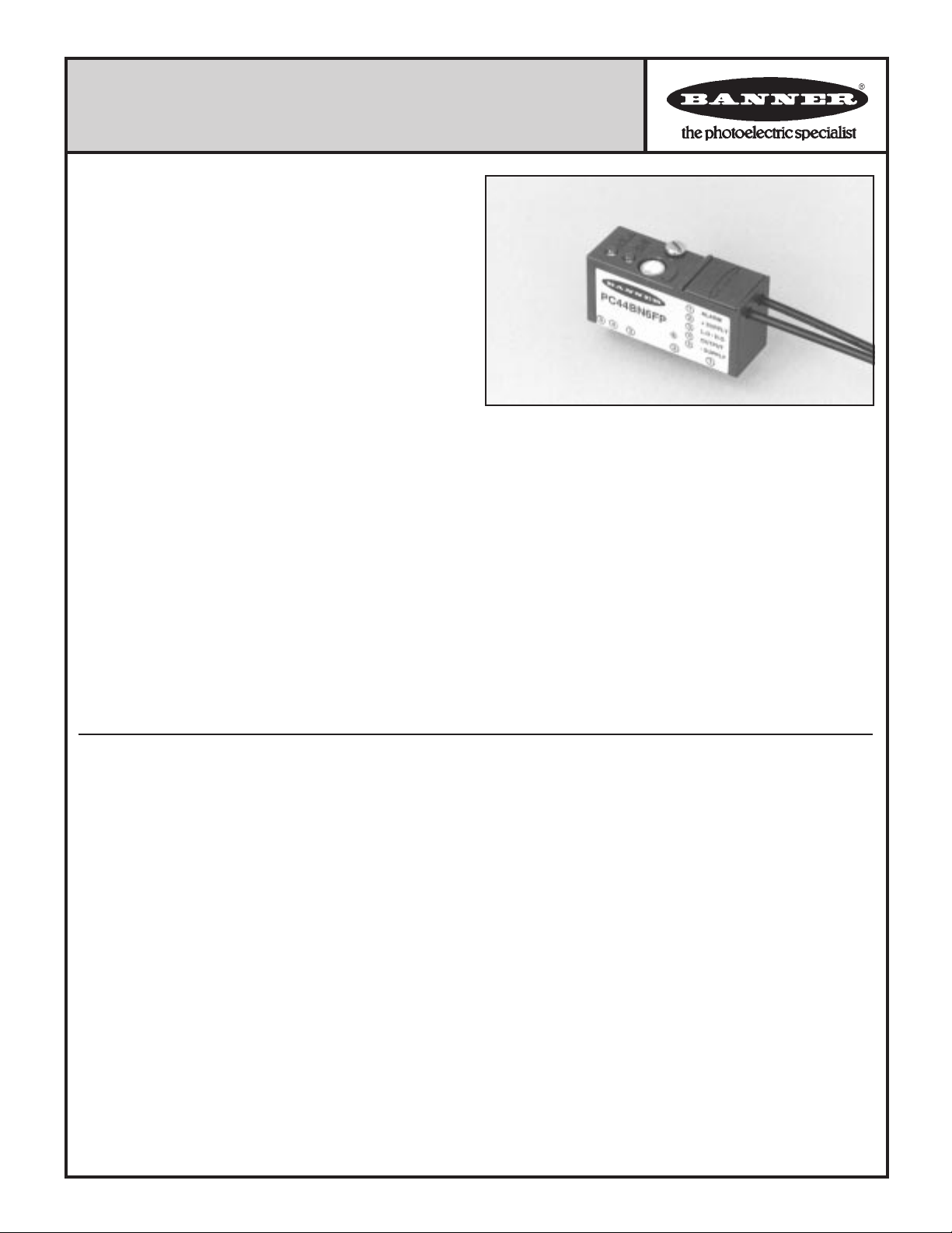
PC44 Series sensor module
with plastic fiber optic assembly attached.
not exceed 100 mA. PC44 modules can interface to a wide variety
of loads.
Two top-mounted LED indicators light to indicate POWER ON,
OUTPUT OVERLOAD, ALIGNMENT, and EXCESS GAIN 1 to
1.5x (LOW GAIN) conditions. The LOW GAIN indication corresponds to the "on" state of the module's alarm output.
Fiber optic assemblies are available as either coiled or straight fibers,
bifurcated or individual, and with a variety of sensing end styles (see
page 4). Representative sensing range and beam pattern information for the opposed and diffuse sensing modes is given on page 3.
PC44s may be soldered directly to a printed circuit board. Also, a
kit of closed-end jacks is available (model PCJ-25; see specifications) to allow the PC44 module to plug into a printed circuit
board. PC44 modules also plug into standard I/O mounting racks.
Specifications and model listings, PC44 modules:
Sensing range: opposed and diffuse sensing modes; see curves, page 3.
Sensing beam: visible red, 680 nanometers.
Supply voltage: 10 to 30V dc at 25 mA maximum, exclusive of load,
at module pins #2 (+Vdc) and #5 (dc common). 10% maximum ripple.
Module model listing and output configurations:
Solid-state dc outputs, selectable for light- or dark-operate:
PC44BN6FP = NPN sinking load output plus NPN sinking alarm output.
PC44BP6FP = PNP sourcing load output plus PNP sourcing alarm output.
Light operate/dark operate mode selection for the load output (mod-
ule pin #4) is done by either connecting or not connecting module pin #3
to +V dc (see page 2).
Light operate mode: Normally open load output conducts when the
receiver sees the emitter's modulated visible red light.
Dark operate mode: Normally open load output conducts when the
receiver does not see the emitter's modulated light.
The alarm output (at module pin #1) is normally open (N.O.), and
conducts whenever the excess gain in the light condition falls below 1.5x.
Module output rating: 100 mA maximum each output.
No false pulse on power-up. (False pulse protection circuit causes a 100
millisecond delay on power-up.) Short-circuit protected.
Off-state leakage current <1 microamp at 30V dc.
On-state saturation voltage <1V at 10 mA dc; <1.5V at 100 mA dc.
When the alarm output is used, the total load may not exceed 100 mA.
Response time: 1 millisecond "on"; 1 millisecond "off".
Printed in USA
Repeatability is 0.25 milliseconds.
Response time and repeatability are independent of signal strength.
Indicators: Two top-mounted LED indicators, one yellow and one
green. Indications are as follows:
GREEN glowing steadily = dc power "on".
GREEN flashing = output overloaded.
YELLOW glowing steadily = excess gain in light condition is >1.5x.
YELLOW flashing = excess gain in light condition is marginal (<1.5x).
Flashing YELLOW corresponds to a conducting (closed) alarm output.
Adjustments: Single-turn SENSITIVITY control on top of module.
Construction: Polypropylene
pins. Completely sealed, epoxy-encapsulated circuitry. Plated steel
mounting (hold-down) screw.
Mounting: Three options are possible.
1) PC44 modules may be soldered directly to a printed circuit board.
2) A set of socket pins is available for PC board mounting.
Socket pin kit (model PCJ-25) contains 25 socket pins (5 pins are
required per module) and 5 hold-down nuts (1 required per module).
3) PC44 modules plug into standard I/O mounting racks. Contact
Banner's applications engineering department for further informa-
tion.
Operating temperature range: -20° to +55°C (-4° to 131°F).
Maximum relative humidity: 90% at 50°C (non-condensing).
housing; gold-plated copper connecting
P/N 32910F7A
Page 2
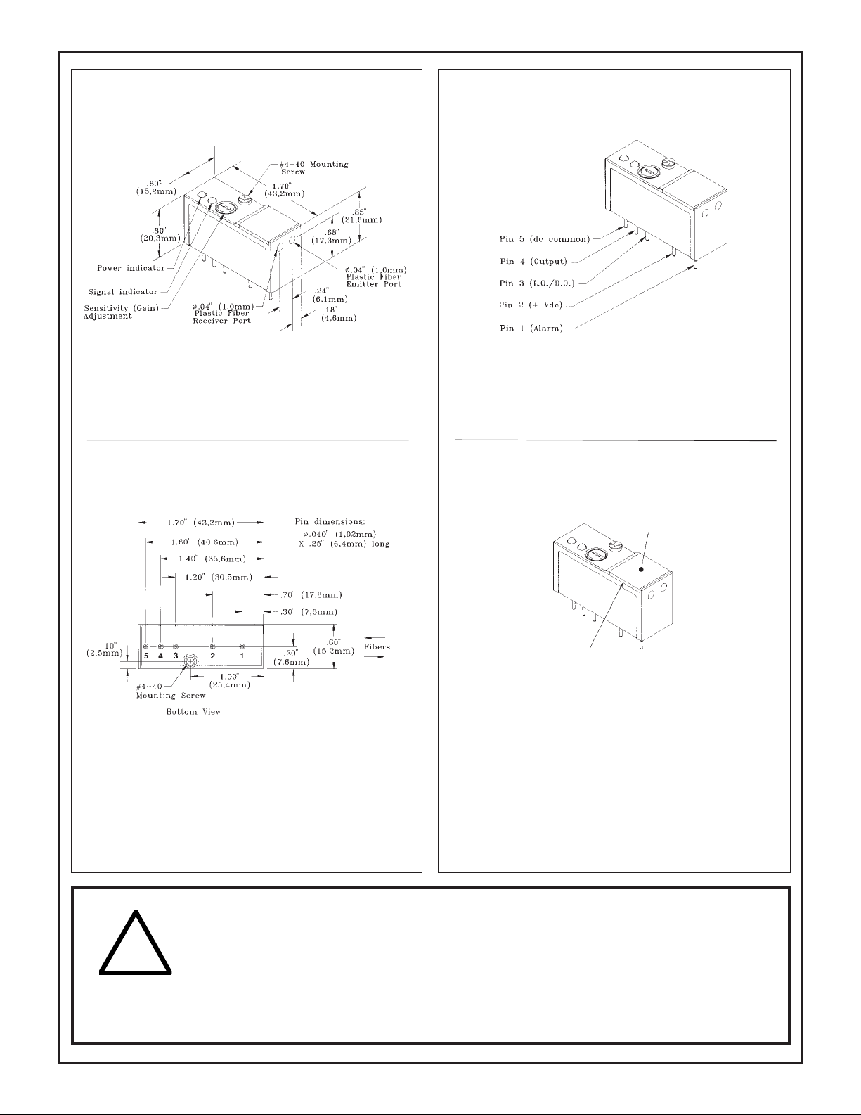
Dimensions & Features, PC44 Series Modules
Pin Identification, PC44 Series Modules
Light/dark operate selection is done at pin #3.
For light operate mode, leave pin #3 unconnected.
For dark operate, connect pin #3 to +V dc.
Dimensions & Pin Locations (module bottom)
Recommended PC-board hole diameters:
Module pins .048" (after plating)
Jacks* .105" (after plating)
Hold-down PEM nut* .166"
*Supplied in kit PCJ-25 (order separately from
module).
Kit PCJ-25 contains 25 jacks and 5 hold-down nuts,
sufficient to mount five PC44 modules.
Fiber Installation
Gripper door
(Lift up here)
Fiber Installation Procedure:
1) Cut fiber to length as described in the data sheet accompanying the fiber.
2) Gently lift up the edge of the gripper door along the "label side" of the
module.
3) Push both fibers into the proper ports* until they stop. While holding the
fibers snugly in place, press the gripper door closed.
*Ports are labeled for emitter and receiver fibers. The difference is not
important when bifurcated fibers are used in the diffuse mode, but may be
a factor when individual fibers are used (opposed sensing mode). The
emitter port is for the fiber on the emitter side of the process; the receiver
port is for the fiber on the receiver side of the process.
WARNING PC44 Series modules do NOT include the self-checking redundant circuitry necessary to allow their use in
personnel safety applications. A sensor failure or malfunction can result in either an energized or a de-energized sensor output
condition.
!
Only MACHINE-GUARD and PERIMETER-GUARD Systems, and other systems so designated, are designed to meet OSHA and ANSI machine safety
standards for point-of-operation guarding devices. No other Banner sensors or controls are designed to meet these standards, and they must NOT be used
as sensing devices for personnel protection.
2
Never use these products as sensing devices for personnel protection. Their use as safety devices may create an unsafe condition
which could lead to serious injury or death.
Page 3

d
Opposed fiber optic sensing mode
1
10
100
10 mm
0.4 in
100 mm
4 in
1000 mm
40 in
1 mm
0.04 in
1000
E
X
C
E
S
S
G
A
I
N
DISTANCE
PC44
Opposed Mode
PIT46U Fibers
Excess Gain Curve
Beam Pattern
PC44
Opposed Mode
38 mm
25 mm
13 mm
0
13 mm
25 mm
38 mm
50 mm
0
PIT46U Fibers
2 in
100 mm
4 in
DISTANCE
150 mm
6 in
200 mm
8 in
250 mm
10 in
1.5 in
1.0 in
0.5 in
0
0.5 in
1.0 in
1.5 in
In opposed mode sensing, emitter and receiver fiber optics are
set up opposite (and facing) each other, and the object to be
detected passes between the fiber optic sensing tips and breaks
the light beam. Two individual (PI Series) fiber optic assemblies are required: one to carry the emitted light and the other to
carry the received light. The curves (above left) show typical
opposed mode performance of a PC44 module fitted with two
PIT46U fibers in the opposed sensing mode.
Opposed mode sensing range may be extended by using lenses
on both emitter and receiver fibers. The curves (above right)
show the typical performance of PIT46U fibers fitted with L2
lenses. L2RA (right-angled) prisms may be used with threadedtip fibers to provide sensing at right angles to the fiber tips,
although at somewhat reduced sensing range compared to
unlensed fibers.
150 mm
100 mm
50 mm
50 mm
100 mm
150 mm
PC44, .040" fibers
0
0
Beam Pattern
Opposed mode, L2 lenses
1.5 m
1 m
.5 m
20 in
40 in
DISTANCE
60 in
80 in
2.5 m
2 m
100 in
Excess Gain Curve
1000
E
X
C
100
E
S
S
PC44
Opposed Mode,
10
G
PIT46U (.040") fibers,
A
L2 lenses
I
N
1
10 mm
100 mm
4 in
DISTANCE
1 m
40 in
0.4 in
10 m
400 in
L2 and L2RA
L2 lens for extended range operation with opposed mode fibers.
Use with PIT46U or PIT46UC. See sensor excess gain curves
for range information. L2RA (not shown)
provides right-angle sensing at
somewhat reduced range.
.365
9,3
.11 Ø glass lens
2,8
.16 Ø
3,8
M2.5 x 0,45
internal threa
6 in
4 in
2 in
0
2 in
4 in
6 in
Standard models of PI Series individual plastic fiber optic assemblies are included in the list at the bottom of page 4.
Banner Engineering Corp. can custom-design plastic fibers to suit the requirements of your particular application. Contact one
of our application engineers by telephone or FAX for a quote on your design.
Diffuse fiber optic sensing mode
Diffuse mode sensing utilizes bifurcated (PB Series) fibers.
These are paired fibers, one of which carries the light from the
emitter element to the sensing point, while the other carries the
light (reflected from the sensed object) from the sensing point
back to the receiver element.
The curves (right) show typical performance of a PC44 module
fitted with a model PBT46U fiber assembly in the diffuse
sensing mode. Diffuse mode sensing range is referenced to a
white test card of 90% reflectance. Less reflective objects will
shorten the sensing range.
Excess Gain Curve
1000
E
X
C
100
E
S
S
10
G
A
I
N
1
0.1 mm
0.004 in
PBT46U Fiber
1 mm
0.04 in
DISTANCE
Diffuse Mode
10 mm
0.4 in
PC44
100 mm
4 in
Standard models of PB Series bifurcated plastic fiber optic
assemblies are included in the list at the bottom of page 4.
Banner Engineering Corp. can custom-design plastic fibers to suit the requirements of your particular application. Contact one
of our application engineers by telephone or FAX for a quote on your design.
Beam Pattern
PC44
Diffuse Mode
7.5 mm
5 mm
2.5 mm
0
2.5 mm
5 mm
7.5 mm
PBT46U Fiber
50 mm
37.5 mm
25 mm
12.5 mm
0
1.0 in
0.5 in
DISTANCE
1.5 in
2.0 in
Distance to 90% reflectance white test card
62.5 mm
2.5 in
0.3 in
0.2 in
0.1 in
0
0.1 in
0.2 in
0.3 in
3
Page 4

Banner Plastic fiber optic assemblies
Banner plastic fiber optics are an economical alternative to glass
fiber optics for piping photoelectric sensing light into and out of
confined areas where the environmental conditions allow.
They are offered in two general styles: individual and bifurcated.
Individual (PI Series) fibers are used in pairs in the opposed sensing
mode. One fiber transmits the light to the sensing location, while
the other fiber returns the received light to the sensor.
Bifurcated (PB Series) plastic fiber assemblies are "two-way"
fibers having a single sensing end that both emits and receives light
and dual control (sensor) ends which attach separately to the
sensor. Plastic fiber optic assemblies are available in a variety of
sensing end styles. Coiled assemblies may be used successfully on
reciprocating mechanisms for millions of cycles.
Banner plastic fiber optic assemblies are available in two monofilament core diameters: .020-inch and .040-inch. PC44 Series
modules require .040-inch core fibers.
Banner standard plastic fiber optic assemblies are unterminated on
the control (sensor) end. Fiber assemblies are approximately 6 feet
(2m) in length. They can be used "as-is", or they may be cut to a
shorter length. Each assembly is supplied with a cutting device to
allow the fiber to be easily cut to length. Cutting instructions are
included with the fiber assembly.
Due to their light transmission properties, plastic fiber optics are
recommended for use only with visible light fiber optic sensors.
Banner Engineering can custom design plastic fibers to suit your
application requirements. Contact one of our application engi-
neers by telephone or FAX for a quote on your particular design.
Specifications, Banner plastic fiber optic assemblies
SENSING RANGE: refer to the excess gain curves for the fiber optic sensor
to be used. The selection charts at the front of the Banner product catalog list
all self-contained fiberoptic sensors and page references for gain curves.
TEMPERATURE EXTREMES: temperatures below -30° C will cause
embrittlement of the plastic materials but will not cause transmission loss.
Temperatures above +70° C will cause both transmission loss and fiber
shrinkage.
REPEAT BENDING/FLEXING: life expectancy of plastic fiber optic cable
is in excess of one million cycles at bend radii of no less than the minimum
(stated below) and a bend of 90 degrees or less. Avoid stress at the point where
the cable enters the sensor ("control end") and at the sensing end tip. Coiled
plastic fiberoptic assemblies are recommended for any application requiring
reciprocating fiber motion.
OPERATING TEMPERATURE: -30 to +70° C (-20 to +158° F).
CHEMICAL RESISTANCE: the acrylic core of the monofilament optical
fiber will be damaged by contact with acids, strong bases (alkalis) and solvents.
The polyethylene jacket will protect the fiber from most chemical environments. However, materials may migrate through the jacket with long term
exposure. Samples of fiber optic material are available from Banner for testing
and evaluation.
MINIMUM BEND RADIUS: 1.0 inch (25mm) for .040 inch diameter fibers.
CONSTRUCTION:
OPTICAL FIBER: plastic monofilament
PROTECTIVE JACKET: black polyethylene
THREADED END TIPS and HARDWARE: nickel-plated brass
PROBE END TIPS: annealed (bendable) T304 stainless steel
ANGLED END TIPS: hardened T304 stainless steel
FERRULED END TIPS: T303 stainless steel
Banner plastic fiber optic assemblies are available either straight or coiled, individual or
bifurcated, and with a variety of sensing tip styles (see photo). Models compatible with
PIF46U
(2 shown)
PIT46U
(2 shown)
WARRANTY: Banner Engineering Corporation warrants its products to be free from defects for one year. Banner Engineering Corporation will repair or
replace, free of charge, any product of its manufacture found to be defective at the time it is returned to the factory during the warranty period. This warranty
does not cover damage or liability for the improper application of Banner products. This warranty is in lieu of any other warranty either expressed or implied.
Banner Engineering Corp. 9714 10th Avenue No., Minneapolis, MN 55441 Telephone: (612) 544-3164 FAX (applications): (612) 544-3573
PIT46UC
PBT46U
PBF46U
PC44 Series modules include the full line of Banner .040" core diameter plastic fibers:
PBF46U straight bifurcated fiber, ferruled sensing tip (for diffuse sensing)
PBP46U straight bifurcated fiber, bendable probe sensing tip (for diffuse sensing)
PBP46UC coiled bifurcated fiber, bendable probe sensing tip (for diffuse sensing)
PBT46U straight bifurcated fiber, threaded sensing tip (for diffuse sensing)
PBT46UC coiled bifurcated fiber, threaded sensing tip (for diffuse sensing)
PIF46U straight individual fiber, ferruled sensing tip (for opposed sensing)
PIP46U straight individual fiber, bendable probe sensing tip (for opposed sensing)
PIP46UC coiled individual fiber, bendable probe sensing tip (for opposed sensing)
PIT46U straight individual fiber, threaded sensing tip (for opposed sensing)
PIT46UC coiled individual fiber, threaded sensing tip (for opposed sensing)
NOTES: Individual fibers are sold in pairs. For further information about Banner
plastic fiber optic assemblies, request product data sheet P/N 32881.
 Loading...