

Page 1
MEASUREMENT & INSPECTION
®
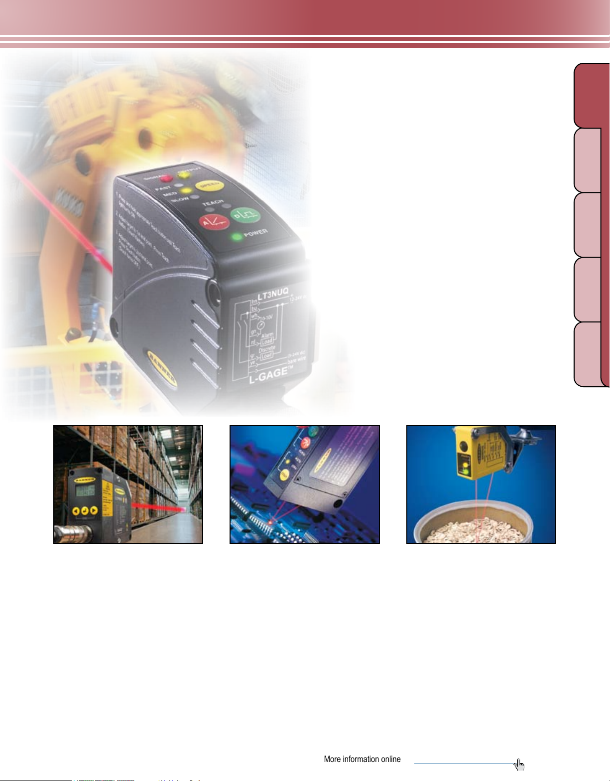
L-GAGE
Light Gauging Sensors
LT3 page 244
• Exceptionally accurate advanced time-of-flight
sensing technology provides precise measurements
over long ranges.
• Retroreflective mode sensor has 50 m range.
• Ranges with diffuse mode sensor are 5 m for white
targets and 3 m for gray targets.
• Sensors offer either analog and discrete, or
dual-discrete output, with independent window limits.
GAUGI NG
LIGHT
ULTRASONIC
LIGHT SCR EENS
MEASURING
TE MP ER ATU RE
LT7 page 248
• Extremely long-range sensor uses a
Class 1 laser beam for accuracy over long
distances.
• Retroreflective mode sensor has
250 m range.
• Ranges with diffuse mode sensor are up
to 10 m for white, 7 m for gray and 3 m for
black targets.
• Models are available with discrete output
only or with discrete and analog output.
• RS-422 or SSI compatible serial
connections are provided.
LG page 252
• One-piece laser gauging system requires
no separate controller.
• Ultra narrow beam delivers precise
distance, height and thickness
measurement and gauging.
• Two sensing ranges are available:
45 to 60 mm and 75 to 125 mm.
RADAR
Q50 page 256
• LED sensor delivers laser-like performance
in a compact, low-cost package.
• Models are available to gauge distances
either from 100 to 400 mm or 50 to 200 mm,
with analog or discrete output.
• Features include high resolution and a fast,
selectable response time.
More information online at bannerengineering.com
243
Page 2
MEASUREMENT & INSPECTION
QD CABLES
REFLECTORS
LASE R R ETRO
LASER DIFFU SE
BRACKETS
RADIANT POWER 0.15mW
10ns PULSE, 1MHz
650 - 670
nm
Complies with IEC 60825-1:
and 21 CFR 1040.10 & 1040.
except for deviations purs
Laser Notice No. 50, date
d
July 26, 2001
LASER LIGHT
CLASS 1 LASER PRODUCT
Laser ligh
t
emitted fr
o
this apertue
RADIANT POWER 0.5mW
10ns PULSE, 1MHz
650 - 670 nm
COMPLIES TO 21 CFR PART
1040.10 AND EN60825-1:1994
LASER LIGHT
DO NOT STARE INTO BEAM
CLASS 2 LASER PRODUCT
Av oid exposure- las
e
light emit
t
thisture
L-GAGE® LT3
LIGHT
ULTRASONIC
MEASURING
TE MP ER ATU RE
RADAR
GAUGI NG
SLOT & LABEL PART & AREA
COLOR &
LIGHT SCR EENS
PICK-TO-LIGHT
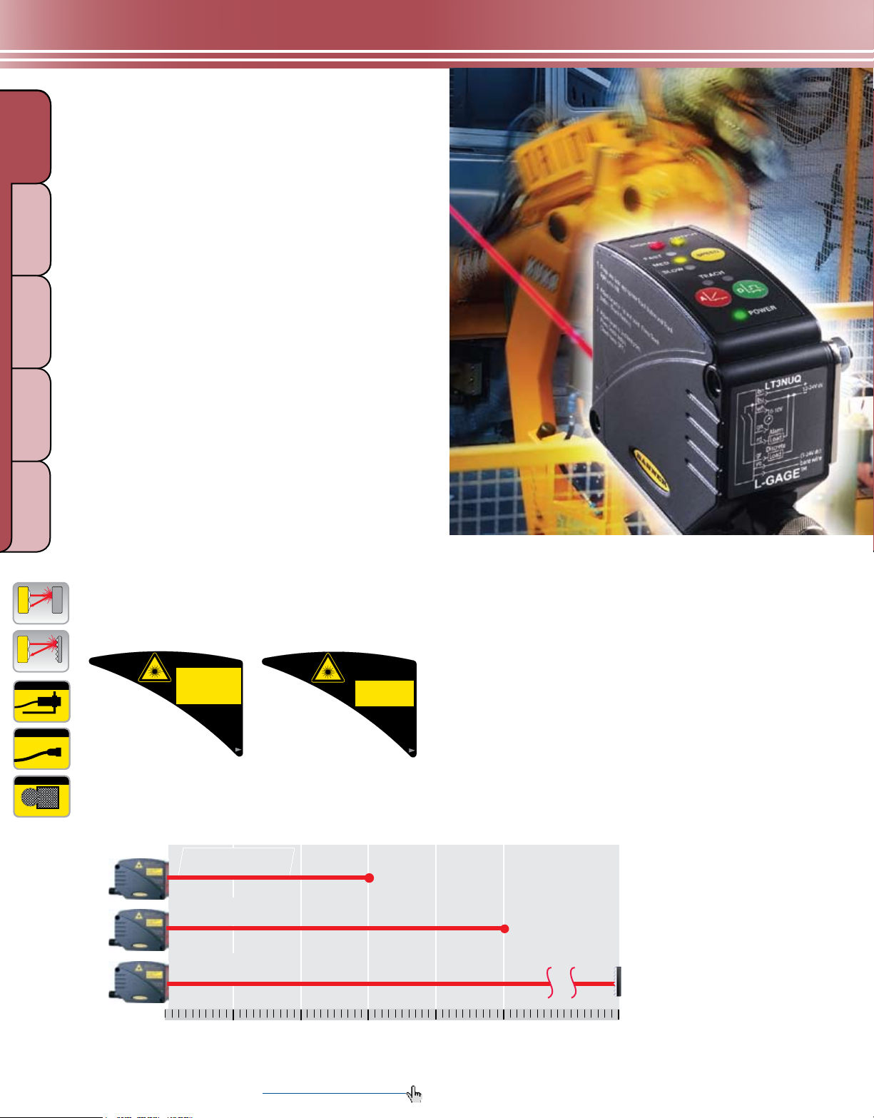
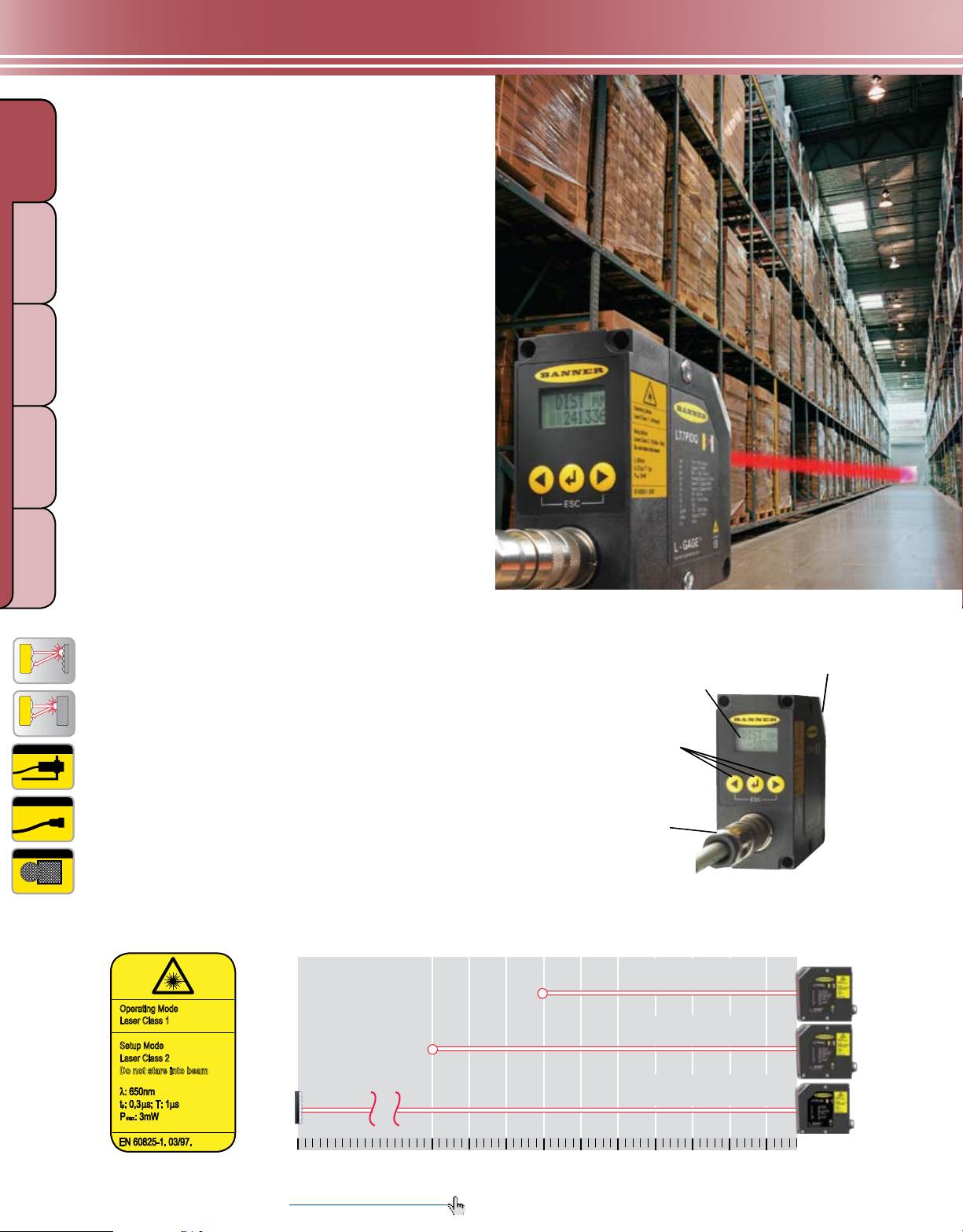
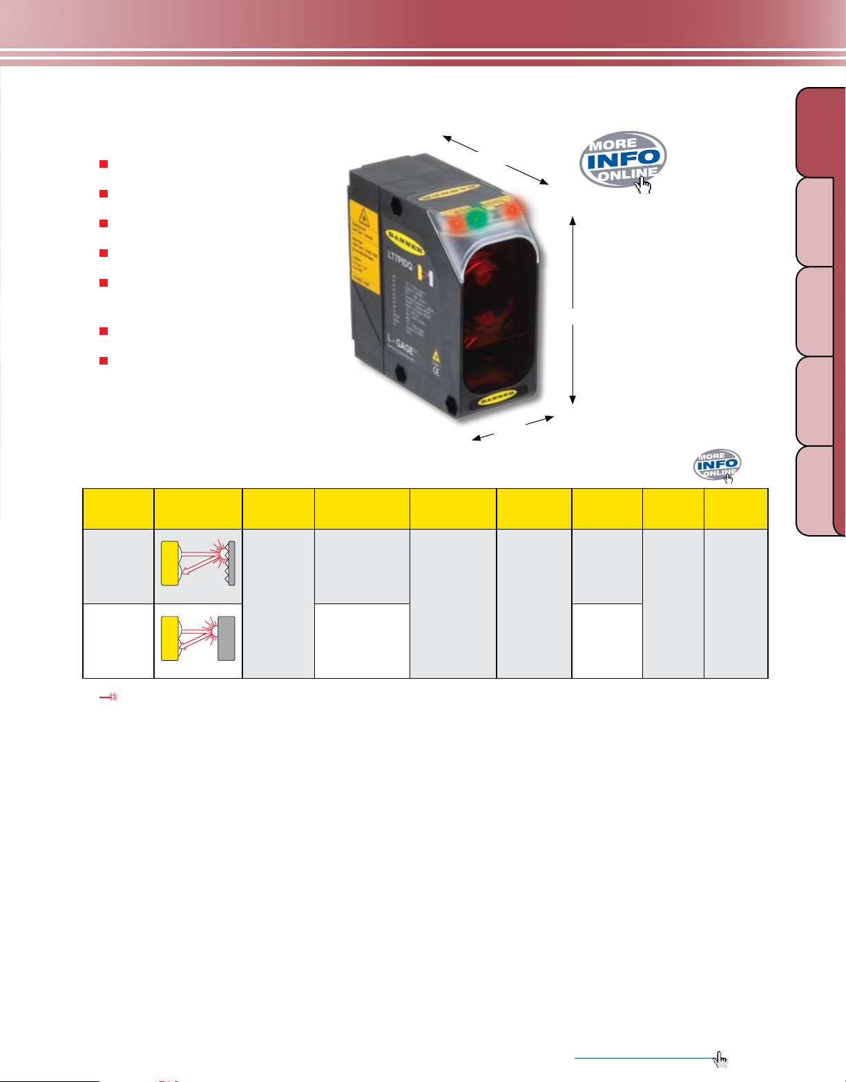
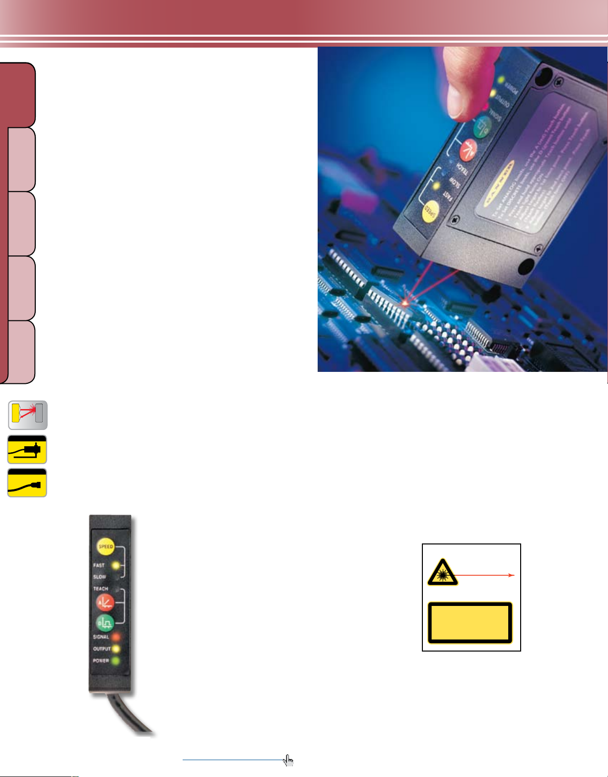
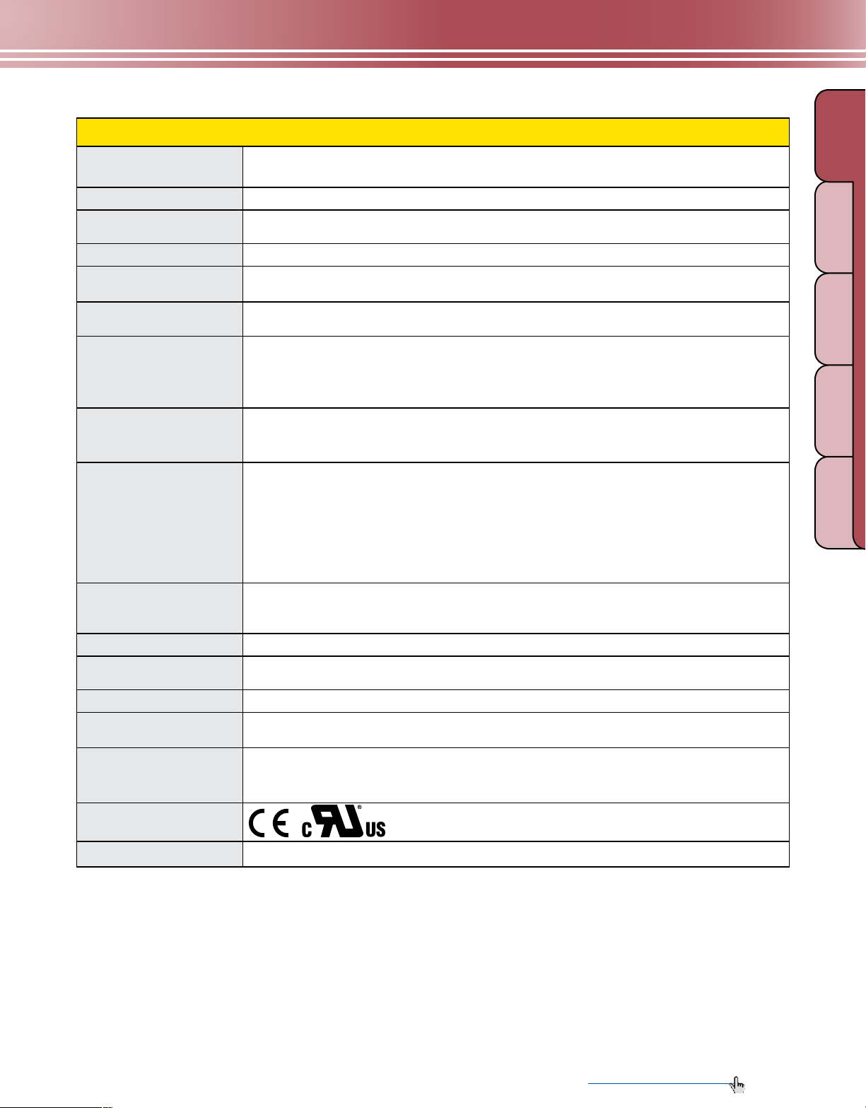
Laser DistanceGauging Sensors
Advanced time-of-flight technology at less cost
The L-GAGE® LT3 sensor uses “time-of-ight” technology
for precise, long-distance gauging at the speed of light.
The microprocessor-controlled laser distance-gauging
sensor features a unique design for exceptional accuracy
and range at a much lower cost than competitive lasergauging devices. Precise performance and low price
make the LT3 an ideal solution for a variety of precision
inspection applications.
lUMINESCENCE
• Available in accurate diffuse-mode models with ranges
to 5 m and retroreflective models with a 50 m range
• Emits one million pulses per second
• Reliably detects angled targets
Analog & discrete outputs, or dual-discrete models
The LT3 can include both a discrete (switched) output
and an analog output in the same unit, with independently
programmable window limits. For added exibility, the
analog output is available in a choice of 4 to 20 mA
or 0 to 10V dc. You can also choose models with two
independent discrete outputs, selectable PNP (sourcing)
or NPN (sinking).
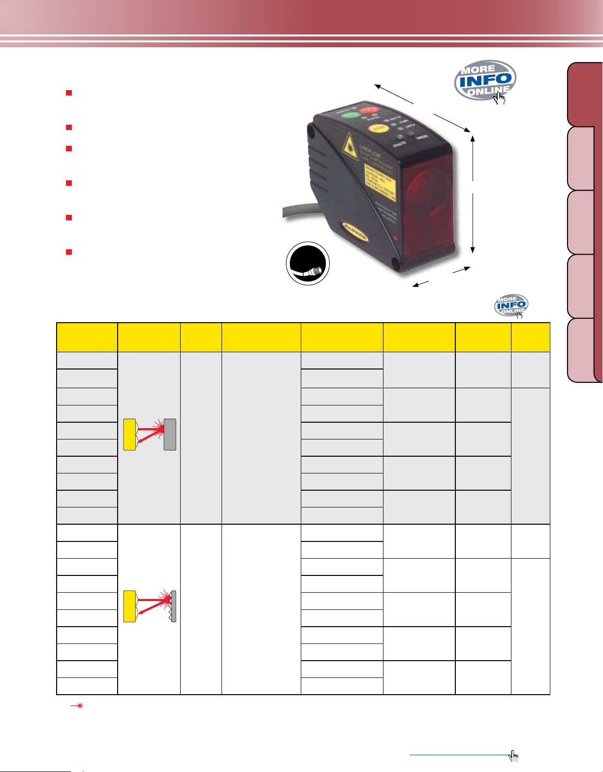
Compact, self-contained design
• The LT3’s design conserves production space and
decreases setup time.
• The self-contained system measures just 68.5 by 35.3
by 87.0 mm, to fit and function in tighter spaces than
competitive systems.
PAGE 370
8-Pin Euro
PAGE 416
PAGE 425
Class 1 Label Class 2 Label
LT3 Sensing Ranges
Diffuse models with
gray targets: 0.3 - 3 m
Diffuse models with
white targets: 0.3 - 5 m
Retroreective models with
retroreector: 0.5 - 50 m
244 More information online at bannerengineering.com
Meters
1 2 3 4 5 . . . 50
Simple 3-step programming
Programming the LT3 takes just three short steps, which
are conveniently printed on the side of the sensor. In
addition, push-button TEACH-mode programming sets
custom sensing windows. And remote programming
offers added security and convenience.
Page 3
MEASUREMENT & INSPECTION
Detailed
Dimension
s
LASER DIFFUSE
LASER RETRO
Dow nlo a
d
PDF
QPMA
E
U
R
O
-
S
T
Y
L
E
•
P
I
G
T
A
I
L
•
P
U
R
•
C
A
B
L
E
C
A
L
L
F
A
C
T
O
R
Y
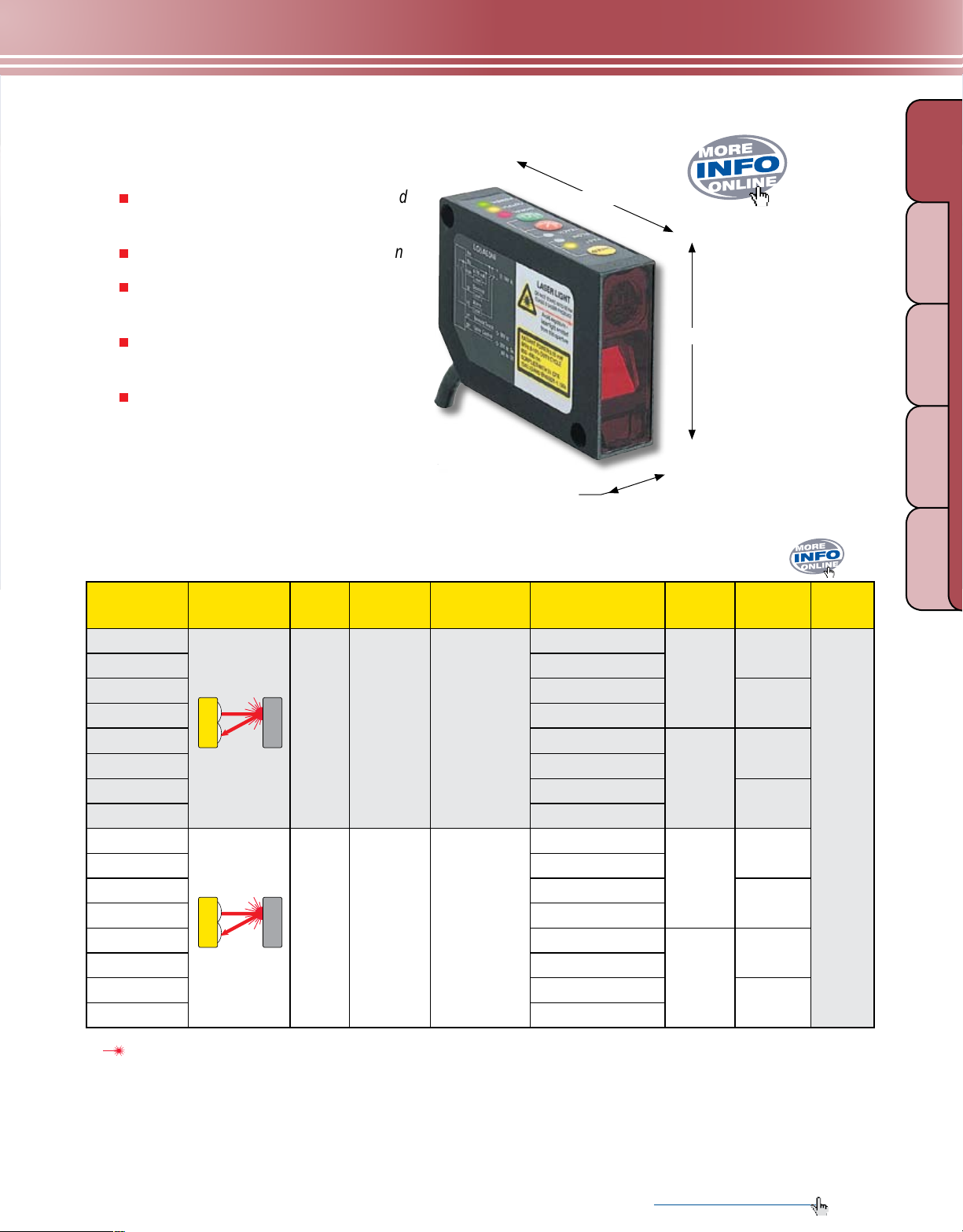
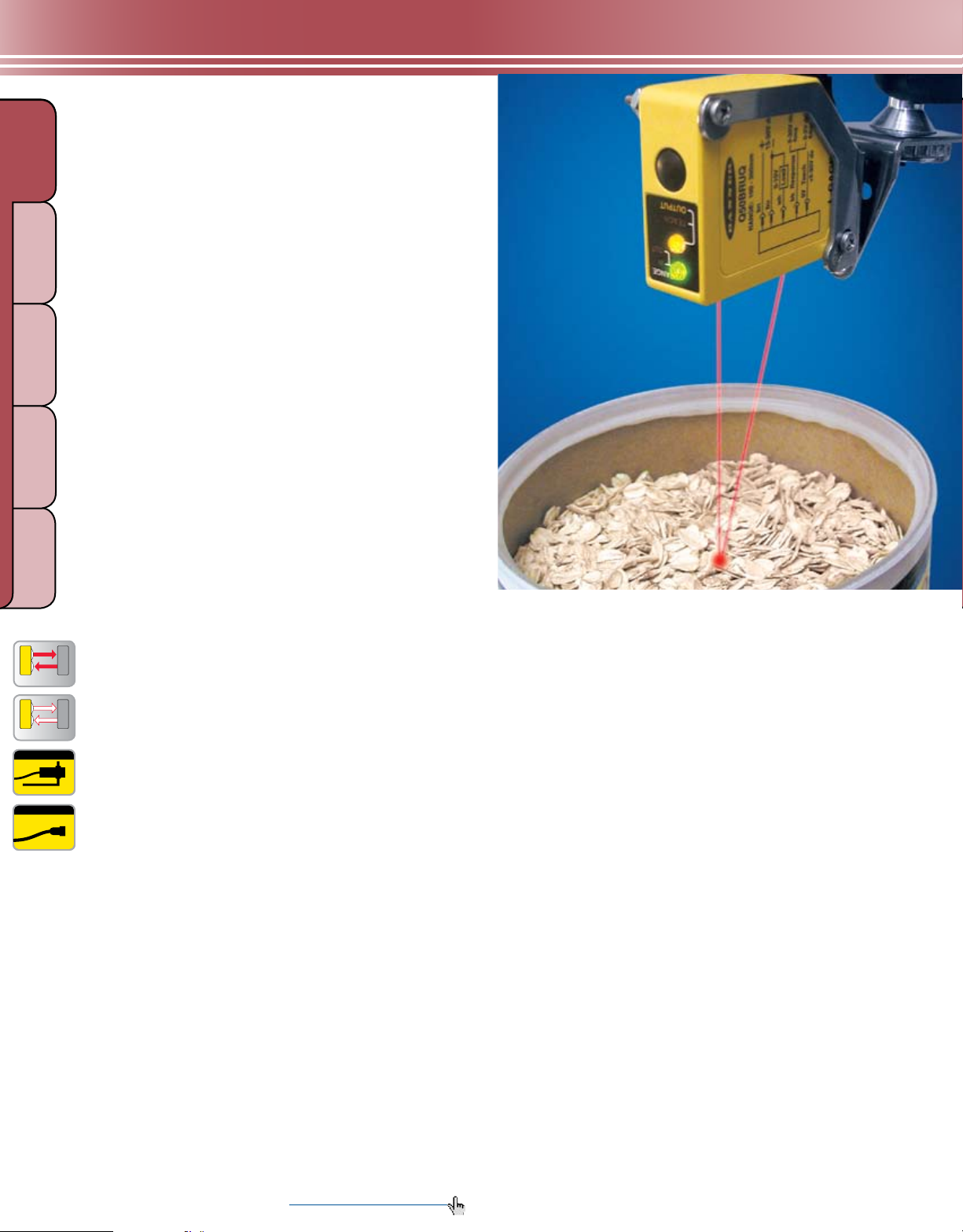
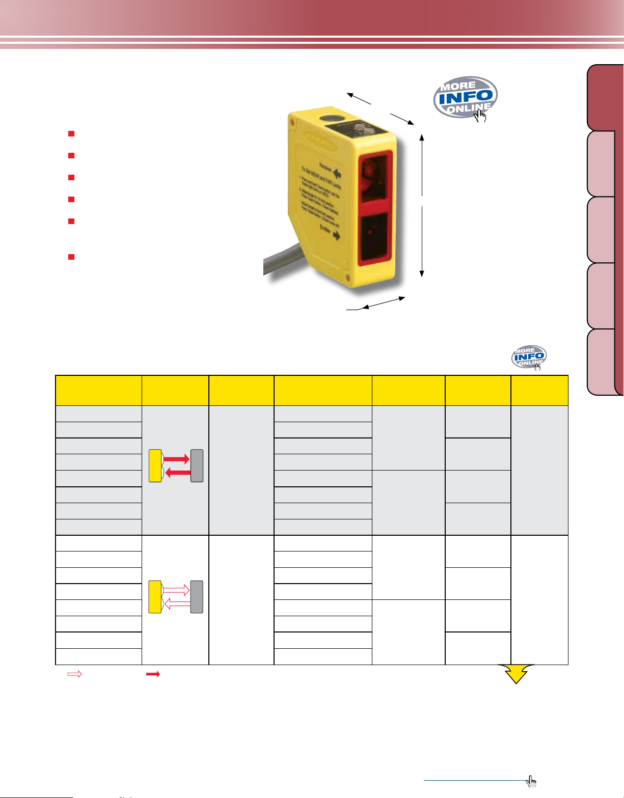
L-GAGE® LT3 Sensors
Programmable output response for three
speeds using simple push-button TEACH
Bright, visible laser spot to simplify alignment
Analog outputs in a choice of 0 to 10V dc or
4 to 20 mA sourcing
Rugged construction to withstand demanding
sensing environments; rated IEC IP67, NEMA 6
2 m or 9 m attached cable, or 8-pin Euro-style
quick-disconnect
8-pin Euro-style QD cables with shield ordered
separately (see page 416)
L-GAGE® LT3, 12-24V dc
Models
LT3BD
LT3BDQ
Sensing
Mode/LED*
Laser
Class
Sensing
Distance Cable**
2 m
8-pin Euro QD
87.0 mm
35.3 mm
Discrete
Output
Dual NPN or
PNP Selectable
68.5 mm
Analog
Output
None
Data
Sheet
68503
GAUGI NG
LIGHT
ULTRASONIC
LIGHT SCR EENS
MEASURING
TE MP ER ATU RE
RADAR
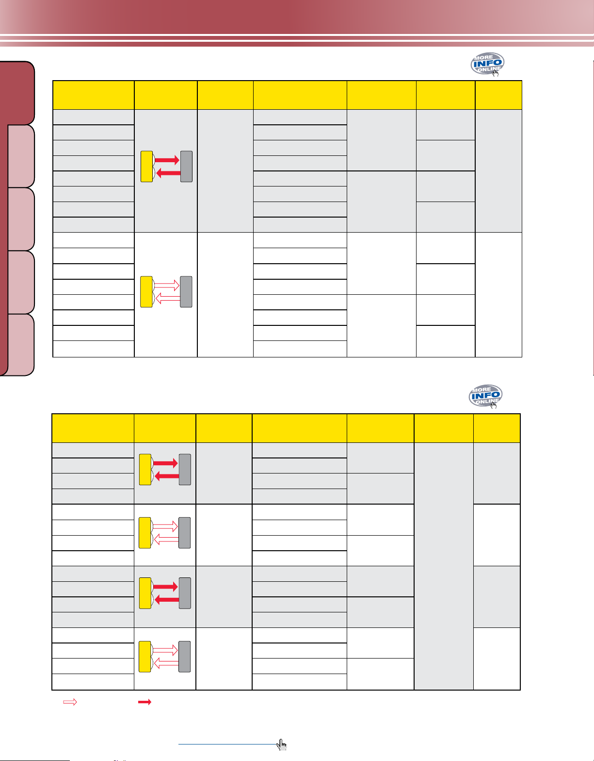
LT3PU
LT3PUQ
LT3NU
LT3NUQ
LT3PI
LT3PIQ
LT3NI
LT3NIQ
LT3BDLV
LT3BDLVQ
LT3PULV
LT3PULVQ
LT3NULV
LT3NULVQ
LT3PILV
LT3PILVQ
LT3NILV
LT3NILVQ
Class 2
Class 1
0.3 to 5 m
for 90% reectivity
white card
(see Performance
Curve RRC-1 on
page 510 for more
information)
0.5 to 50 m
†
(see Performance
Curve RRC-2 on
page 510 for more
information)
2 m
8-pin Euro QD
2 m
8-pin Euro QD
2 m
8-pin Euro QD
2 m
8-pin Euro QD
2 m
8-pin Euro QD
2 m
8-pin Euro QD
2 m
8-pin Euro QD
2 m
8-pin Euro QD
2 m
8-pin Euro QD
PNP 0 to 10V dc
NPN 0 to 10V dc
PNP 4 to 20 mA
NPN 4 to 20 mA
Dual NPN or
PNP Selectable
PNP 0 to 10V dc
NPN 0 to 10V dc
PNP 4 to 20 mA
NPN 4 to 20 mA
None
65742
68503
68504
Visible Red Laser
*
** For 9 m cable, add suffix W/30 to the 2 m model number (example, LT3BD W/30). A model with a QD requires a mating cable (see page 416).
†
Retroref lective range specified using included model BRT-TVHG -8X10P high-grade target.
More information online at bannerengineering.com
245
Page 4
LIGHT
ULTRASONIC
MEASUREMENT & INSPECTION
Sensing Beam
GAUGI NG
Sensing Range
SLOT & LABEL PART & AREA
Supply Voltage and Current
Supply Protection Circuitry
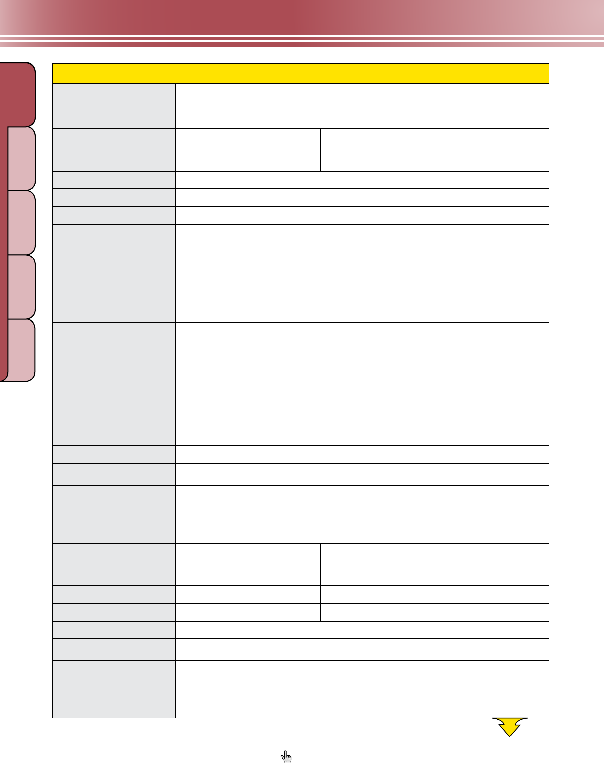
L-GAGE® LT3 Specifications
Typical beam dia: 6 mm @ 3 m
Typical laser lifetime: 75,000 hours
Diffuse: 658 nm visible red IEC and CDRH Class 2 laser; 0.5 mW max. radiant output power
Retroreflective: 658 nm visible red IEC and CDRH Class 1 laser, 0.15 mW max. radiant output power
Diffuse:
90% white card: 0.3 to 5 m
18% gray card: 0.3 to 3 m
6% black card: 0.3 to 2 m
12 to 24V dc (10% max. ripple); 108 mA max. @ 24V dc or [2600/V dc] mA
Protected against reverse polarity and transient voltages
Retroreflective:
0.5 to 50 m (using supplied target)
MEASURING
TE MP ER ATU RE
RADAR
COLOR &
LIGHT SCR EENS
PICK-TO-LIGHT
Delay at Power-up
Output Rating
lUMINESCENCE
Output Configuration
Output Protection
Output Response Time
Resolution/Repeatability
Color Sensitivity (typical)
Analog Linearity
1 second; outputs do not conduct during this time
Discrete (switched) output: 100 mA max.
OFF-state leakage current: less than 5 µA
Output saturation NPN: less than 200 mV @ 10 mA; less than 600 mV @ 100 mA
Output saturation PNP: less than 1.2V at 10 mA; less than 1.6V at 100 mA
Analog voltage output: 2.5 kΩ min. load impedance (voltage sourcing)
Analog current output: 1 kΩ max. @ 24V; max. load resistance = [Vcc-4.5/0.02 Ω] (current sourcing)
Discrete (switched): Solid-state switch; NPN (current sinking) or PNP (current sourcing), depending on
model. Dual-discrete models feature selectable NPN or PNP, depending on wiring hookup.
Analog output: 0 to 10V dc or 4 to 20 mA
Protected against short circuit conditions
Discrete output
Fast: 1 millisecond ON/OFF Medium: 10 milliseconds ON/OFF Slow: 100 milliseconds ON/OFF
Diffuse Analog Voltage output (-3 dB)
Fast: 450 Hz (1 millisecond average/1 millisecond update rate)
Medium: 45 Hz (10 milliseconds average/2 milliseconds update rate)
Slow: 4.5 Hz (100 milliseconds average/4 milliseconds update rate)
Retroreflective Analog Voltage output (-3 dB)
Fast: 114 Hz (6 milliseconds average/ 1 millisecond update rate)
Medium: 10 Hz (48 milliseconds average/ 1 millisecond update rate)
Slow: 2.5 Hz (192 milliseconds average/ 1 millisecond update rate)
See charts RRC-1 and RRC-2 on page 510.
Diffuse: 90% white to 18% gray: less than 10 mm; 90% white to 6% black: less than 20 mm.
See chart CSC-1 on page 511.
Retroreflective: ± 60 mm from 0.5 to 50 m (0.12% of full scale)
(Specied @ 24V dc, 22° C using supplied BRT-TVHG-8X10P retroreector)
Diffuse: ± 30 mm from 0.3 to 1.5 m; ± 20 mm from 1.5 to 5 m
(Specied @ 24V dc, 22° C using a 90% reectance white card)
Discrete Output Hysteresis
Diffuse
Fast: 10 mm
Medium: 5 mm
Slow: 3 mm
Temperature Effect
Minimum Window Size
Remote TEACH Input
Remote TEACH
Adjustments
Diffuse: less than 2 mm/ ° C Retroreflective: less than 3 mm/° C
Diffuse: 20 mm Retroreflective: 40 mm
18 kΩ min. (65 kΩ at 5V dc)
To teach: Connect yellow wire to +5 to 24V dc
To disable: Connect yellow wire to 0 to +2V dc (or open connection)
Response speed: Push button toggles between fast, medium and slow (see Output Response Time)
Window limits (analog or discrete): TEACH-mode programming of near and far window limits.
Limits may also be taught remotely using TEACH input.
Analog output slope:
The rst limit taught is assigned to minimum output current or voltage (4 mA or 0V dc)
246 More information online at bannerengineering.com
Retroreflective
Fast: 20 mm
Medium: 10 mm
Slow: 6 mm
More on
next page
Page 5
MEASUREMENT & INSPECTION
Laser Control
Indicators
Construction
Environmental Rating
Connections
Operating Conditions
Application Notes
Certifications
Hookup Diagrams
L-GAGE® LT3 Specifications
Connect red wire to +5 to 24V dc to enable laser beam; connect to 0 to +1.8V dc
(or open connection) to disable; when sensor is powered laser enable time is 100 millisecond delay on
enable, when sensor is powered.
Green Power ON LED: Indicates when power is ON, overloaded output and laser status
Yellow Output LED: Indicates when discrete load output is conducting
Red Signal LED: Indicates target is within sensing range and the condition of the received light signal
Yellow Speed LED: Indicates the response speed setting
Red/Yellow TEACH LEDs: In programming mode; indicate active output(s)
Housing: ABS/polycarbonate blend
Window: Acrylic
Quick-disconnect: ABS/polycarbonate blend
IP67; NEMA 6
2 m or 9 m shielded 7-conductor (with drain) PVC-jacketed attached cable, or 8-pin Euro-style
quick-disconnect. QD cables are ordered separately. See page 416.
Temperature: 0° to +50° C Relative humidity: 90% at 50° C (non-condensing)
• For best accuracy, allow 30-minute warm-up before programming or operating
• Retroreective performance specications are based on use with supplied BRT-TVHG-8X10P
high-grade target. Results may vary with other retroreective target materials.
R
Discrete/Analog Models: NPN: MI01 (p. 532) PNP: MI02 (p. 532)
Dual-Discrete Models: NPN: MI03 (p. 532) PNP: MI04 (p. 532)
(cont’d)
GAUGI NG
LIGHT
ULTRASONIC
LIGHT SCR EENS
MEASURING
TE MP ER ATU RE
RADAR
More information online at bannerengineering.com
247
Page 6
MEASUREMENT & INSPECTION
QD CABLES
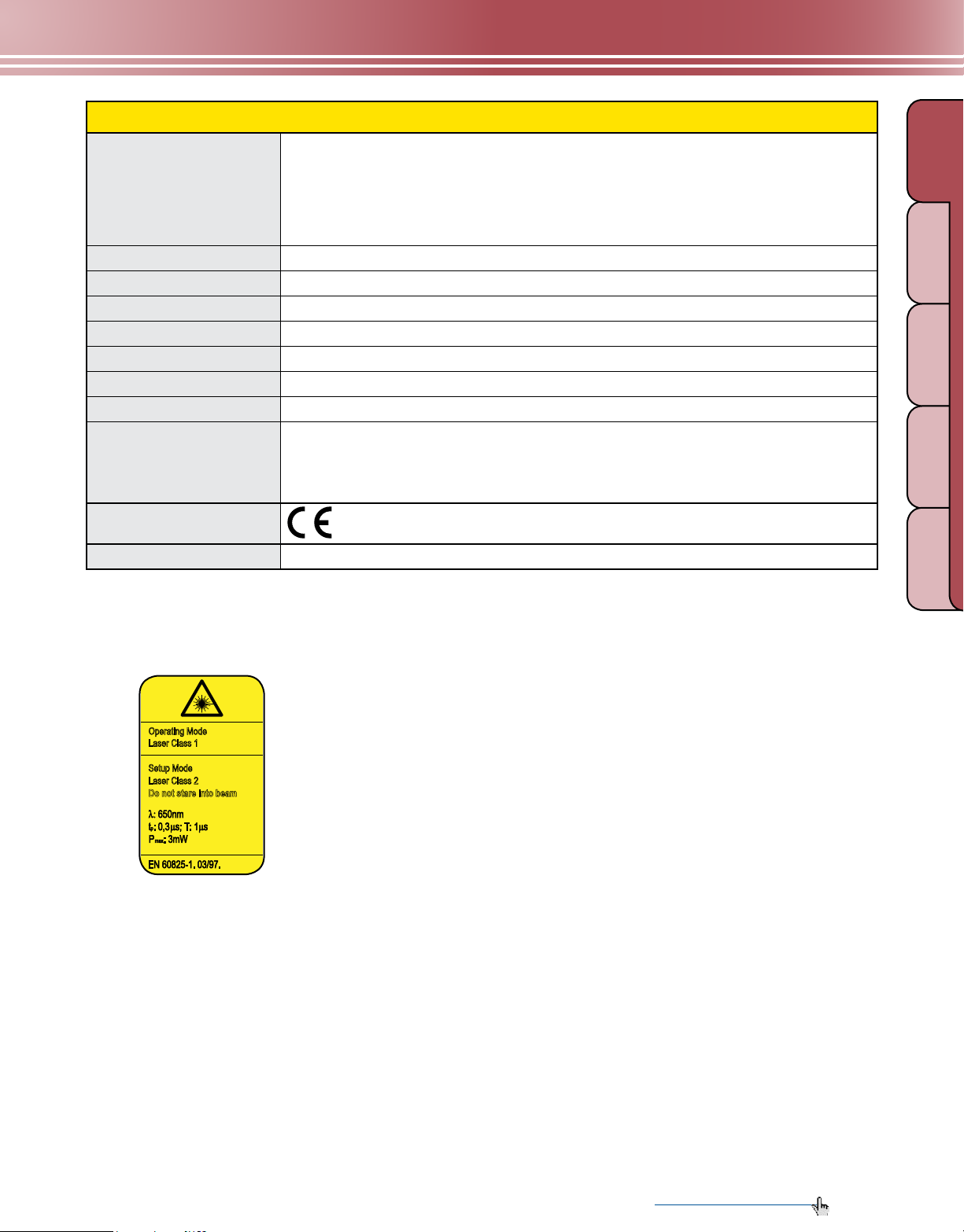
Operating Mode
Laser Class 1
Setup Mode
Laser Class 2
Do not stare into beam
LASE R R ETR O
LASER DIFFUSE
BRACKETS
REFLECTORS
L-GAGE® LT7
LIGHT
ULTRASONIC
MEASURING
TE MP ER ATU RE
RADAR
PAGE 372
12-Pin M16
PAGE 418
PAGE 425
GAUGI NG
SLOT & LABEL PART & AREA
COLOR &
LIGHT SCR EENS
PICK-TO-LIGHT
Highly Accurate
Time-of-Flight Laser
Gauging Sensors
• Available in extremely long-range retroreflective
models with ranges to 250 m or in diffuse models with
ranges to 10 m
• Features TEACH-mode programming, using either
integrated push buttons or a serial interface
• Provides ongoing LCD display of sensing distance in
lUMINESCENCE
millimeters or hundredths of an inch
• Delivers excellent ±10 mm linearity
• Offers choice of RS-422 or SSI-compatible serial
connection
• Uses visible Class 2 alignment laser for
accurate alignment
• Provides quick warmup to minimize drift
Discrete outputs or analog and discrete models
• Diffuse models provide 2 discrete outputs (PNP) and one 4 to 20 mA
output for long-range precision background suppression up to 10 m.
• Retroreflective models offer two discrete outputs (PNP) for extremely
long-range sensing.
• All models offer two alarm outputs with ongoing LCD display for
easy troubleshooting.
Retroreflective models
• Ideal for long-range automated storage and retrieval applications
• Features ±2 mm resolution
Diffuse models
• Features dark-color performance, ideal for automotive applications
• Offers ±4 mm resolution
2-line digital display
of sensing distance
Programming
push buttons
Integral 12-pin
M16 QD connector
Status
Indicator
LED
LT7 Sensing Ranges
Diffuse models with
gray targets: 0.5 - 7 m
Diffuse models with
white targets: 0.5 - 10 m
Retroreflective models with
specified reflector: 0.5 - 250 m
Meters
250 . . . 10 9 8 7 6 5 4 3 2 1
248 More information online at bannerengineering.com
Page 7
L-GAGE® LT7 Sensors
Detailed
Dimension
s
LASER RETRO
LASER DIFFUSE
Dow nlo a
d
PDF
Status Indicator LEDs
2-line digital display
Programming push buttons
MEASUREMENT & INSPECTION
95.0 mm
GAUGI NG
LIGHT
ULTRASONIC
Integral 12-pin M16 QD connector
Class 1 sensing laser and Class 2
visible alignment laser
2 PNP Alarm Outputs
RS-422 or SSI-compatible
serial connection
L-GAGE® LT7, 18-30V dc
Models
LT7PLVQ
LT7PIDQ
Sensing
Mode/LED*
Laser
Class
Class 1
Sensing
Laser
(Class 2
Alignment
Laser)
Sensing
Distance*** Cable**
0.5 to 250 m
12-pin
M16 QD
0.5 to 10 m
42.0 mm
Discrete
Output
2 PNP
93.0 mm
Analog
Output Serial
—
4-20 mA
RS-422
or
SSI
Data
Sheet
120244
LIGHT SCR EENS
MEASURING
TE MP ER ATU RE
RADAR
*
** A model with a Q D requires a mating c able (see page 418).
*** Diffuse-mode range specified using a 90% reflectance white card.
Infrared Laser
Retroreflective-mode range specified using a BRT-250, BRT-540 or BRT-700 retroreflective target (see page 429).
More information online at bannerengineering.com
249
Page 8
LIGHT
MEASUREMENT & INSPECTION
Sensing Range
GAUGI NG
L-GAGE® LT7 Specifications
LT7PLVQ: 0.5 to 250 m (using specified reflector)
LT7PIDQ: 6% Black card: 0.5 to 3 m
18% Gray card: 0.5 to 7 m
90% White card: 0.5 to 10 m
ULTRASONIC
MEASURING
TE MP ER ATU RE
RADAR
SLOT & LABEL PART & AREA
COLOR &
LIGHT SCR EENS
PICK-TO-LIGHT
Supply Voltage and
Current
Power Consumption
Measuring Laser
Laser Control
Spot Size
lUMINESCENCE
Pilot Laser (Alignment)
Discrete & Analog
Output Protection
Discrete Outputs
Discrete Switch Points
Discrete Output
Hysteresis
Alarm Outputs
Analog Output
Maximum Cable Length
18 to 30V dc (10% max. ripple)
Less than 4.5 W @ 25º C
Infrared, 900 nm, Class 1
Measurement laser is ON when sensor is ON. Pilot (visible) laser enabled during Programming mode;
alternates with measurement laser.
Distance Spot Size
LT7PLVQ: 10 m ø 20 mm
50 m ø 100 mm
100 m ø 200 mm
250 m ø 500 mm
LT7PIDQ: 4 m 3 x 10 mm
6 m 4 x 12 mm
10 m 10 x 20 mm
Visible red, 650 nm, Class 2
Protected against continuous overload and short circuit
(2) 100 mA, PNP
Adjustable in 1 mm steps
Adjustable, 10 mm min.
50 mA, PNP (NO)
LT7PLVQ: None
LT7PIDQ: 4-20 mA
100 m
Output Response Time
Linearity
Resolution/Repeatability
Color Sensitivity
Temperature Effect
Minimum Analog
Window Size
Adjustments
Serial Interface
Serial Measurement Speed
12 milliseconds
±10 mm
LT7PLVQ: ±2 mm
LT7PIDQ: ±4 mm
LT7PLVQ: Not Applicable
LT7PIDQ: Contact Factory
Less than ± 5 mm over the total sensing range
LT7PLVQ: Not Applicable
LT7PIDQ: 300 mm
Push-button-directed password enable/disable, measurement unit select, offset value select, output
limits set, output mode select, analog output slope select (diffuse models only) and output limit manual
adjust. See data sheet for information.
RS-422 or SSI compatible
SSI: 1.4 milliseconds (SSI cycle 80 microseconds) RS-422: 2.9 milliseconds @ 57.6 kBaud
250 More information online at bannerengineering.com
More on
next page
Page 9
MEASUREMENT & INSPECTION
Operating Mode
Laser Class 1
Setup Mode
Laser Class 2
Do not stare into beam
Indicators
Construction
Weight
Environmental Rating
Connections
Operating Conditions
Storage Temperature
Vibration/Shock
Application Notes
Certifications
Hookup Diagrams
L-GAGE® LT7 Specifications
4 LEDs:
Green: Power ON/OFF
Red: Alarm (Error) LED
Orange: Output 1 and Output 2 conducting LEDs
2-line digital LCD display. See data sheet for more information.
ABS shock-resistant housing; PMMA window; polycarbonate displays
Approximately 230 g
IEC IP67
12-pin M16 connector; 100 m max. cable length; use only cables listed on page 418.
Temperature: -10° to +50° C in continuous operation
-30° to +75° C
EN 60947-5-2
• All specifications are based on the specified surface at constant ambient conditions and following a
minimum operating time of 15 minutes.
• For best accuracy, allow a 15-minute warmup before programming or operating
• Crosstalk avoidance: Light spots must be separated by at least 200 mm.
MI05 (p. 533)
(cont’d)
GAUGI NG
LIGHT
ULTRASONIC
LIGHT SCR EENS
MEASURING
TE MP ER ATU RE
RADAR
Class 1 (Infrared Sensing Laser)
Lasers that are safe under reasonably
foreseeable conditions of operation,
including the use of optical instruments
for intrabeam viewing. Reference
60825-1 Amend. 2 © IEC:2001(E),
section 8.2.
Class 2 (Visible Alignment Laser)
Lasers that emit visible radiation in
the wavelength range from 400 to 700
nm where eye protection is normally
afforded by aversion responses,
including the blink reex. This reaction
may be expected to provide adequate
protection under reasonably foreseeable
conditions of operation, including the
use of optical instruments for intrabeam
viewing. Reference 60825-1 Amend. 2
© IEC:2001(E), section 8.2.
More information online at bannerengineering.com
251
Page 10
MEASUREMENT & INSPECTION
RADIANT POWER 0.2 mW
9.8KHz 11-20% DUTY CYCLE
660 - 680 nm
COMPLIES WITH 21 CFR
1040.10 AND EN60825-1:1994
DO NOT STARE INTO BEAM
CLASS 2 LASER PRODUCT
LASER LIGHT
Avoid exposure laser light emitted
from this aperture
BRACKETS
LASER DIFFU SE
QD CABLES
L-GAGE® LG
LIGHT
MEASURING
PAGE 372
8-Pin Euro
PAGE 416
ULTRASONIC
SLOT & LABEL PART & AREA
COLOR &
TE MP ER ATU RE
PICK-TO-LIGHT
RADAR
Short-range Laser Sensors
GAUGI NG
Extremely compact, self-contained design
The Banner L-GAGE
®
LG Series replaces large, two-piece
laser gauging sensors with a completely self-contained,
compact housing measuring only 55 x 82 x 20 mm.
• Features a one-piece design to conserve
production space
• Wires easily, decreasing setup time
• Provides a highly accurate solution at a much lower cost
LIGHT SCR EENS
• Does not touch parts it measures, so can be used with
lUMINESCENCE
moving processes, hot parts and sticky parts
Ultra-precise & flexible, with analog & discrete outputs
Advanced digital signal processing algorithms make
the LG Series Class 2 modulated visible laser gauging
sensor a powerhouse of performance for a wide range of
measurement applications.
• Features an outstanding maximum resolution of 3 µm for
flat white targets
• Uses an ultra-narrow beam for applications requiring
precise measurement of distance, height or thickness as
well as gauging applications
• Lets you pick the exact range you need with the
push of a button
• Houses discrete (switched) and analog outputs in
the same unit, each independently programmable
252 More information online at bannerengineering.com
Push-button setup for custom-sized sensing windows
Unlike older, inflexible, fixed-range technology, Banner’s
TEACH-mode programming lets you set your own
custom-sized sensing windows anywhere within the
measuring range, using just one push button.
• Available ranges of 45 to 60 mm and 75 to 125 mm
• Can be programmed for analog output, discrete
output or both simultaneously with independently
controlled sensing window limits
Page 11
LASER DIFFUSE
LASER DIFFUSE
L-GAGE® LG Sensors
Detailed
Dimension
s
Dow nlo a
d
PDF
MEASUREMENT & INSPECTION
GAUGI NG
LIGHT
Choice of NPN or PNP discrete output and
either voltage or current analog output
Push-button setup or remote configuration
LED indicators and output programming
push buttons
2 m or 9 m attached cable, or
8-pin Euro-style quick-disconnect
8-pin Euro-style QD cables with shield
ordered separately (see page 416)
L-GAGE® LG5, 12-30V dc
Models
LG5A65PU
LG5A65PUQ
LG5A65PI
LG5A65PIQ
LG5A65NU
LG5A65NUQ
LG5A65NI
LG5A65NIQ
LG5B65PU
LG5B65PUQ
LG5B65PI
LG5B65PIQ
LG5B65NU
LG5B65NUQ
LG5B65NI
LG5B65NIQ
Sensing
Beam/LED*
Laser
Class
Class 2 45-60 mm
Class 2 45-60 mm
82.3 mm
20.2 mm
Sensing
Distance Beam Size Cable**
2 m
At 53 mm:
0.4 mm
x
0.6 mm
Focus
70 mm
At 53 mm:
0.1 mm
Focus
53 mm
8-pin Euro Pigtail QD
2 m
8-pin Euro Pigtail QD
2 m
8-pin Euro Pigtail QD
2 m
8-pin Euro Pigtail QD
2 m
8-pin Euro Pigtail QD
2 m
8-pin Euro Pigtail QD
2 m
8-pin Euro Pigtail QD
2 m
8-pin Euro Pigtail QD
55.3 mm
Discrete
Output
PNP
NPN
PNP
NPN
Analog
Output
0-10V dc
4-20 mA
0-10V dc
4-20 mA
0-10V dc
4-20 mA
0-10V dc
4-20 mA
Data
Sheet
59786
ULTRASONIC
LIGHT SCR EENS
MEASURING
TE MP ER ATU RE
RADAR
Visible Red Laser
*
** For 9 m cable, add suffix W/30 to the 2 m model number (example, LG5A65PU W/30). A model with a QD requires a mating cable (see page 416).
More information online at bannerengineering.com
253
Page 12
MEASUREMENT & INSPECTION
Dow nlo a
d
PDF
LASER DIFFUSE
L-GAGE® LG10, 12-30V dc
LIGHT
ULTRASONIC
MEASURING
TE MP ER ATU RE
RADAR
GAUGI NG
SLOT & LABEL PART & AREA
COLOR &
LIGHT SCR EENS
PICK-TO-LIGHT
Sensing
Models
LG10A65PU
LG10A65PUQ
LG10A65PI
LG10A65PIQ
LG10A65NU
LG10A65NUQ
LG10A65NI
LG10A65NIQ
Visible Red Laser
*
lUMINESCENCE
** For 9 m cable, add suffix W/30 to the 2 m model number (example, LG10A65PU W/30). A model with a QD requires a mating cable (see page 416).
Beam/LED*
Laser
Class
Class 2 75-125 mm
Sensing
Distance
Beam
Size Cable**
At 125 mm:
0.6 mm
x
0.8 mm
Focus
180 mm
8-pin Euro Pigtail QD
8-pin Euro Pigtail QD
8-pin Euro Pigtail QD
8-pin Euro Pigtail QD
2 m
2 m
2 m
2 m
L-GAGE® LG5 and LG10 Specifications
Sensing Beam
Supply Voltage and Current
Supply Protection Circuitry
Delay at Power-up
Output Rating
Output Configuration
Output Protection
Output Response Time
Analog Resolution and
Repeatability of Discrete
Trip Point
Analog Linearity*
*Resolution and linearity
specied @ 24V dc, 22° C, using
a white ceramic test surface (see
Application Notes)
650 nm visible Red IEC and CDRH Class 2 laser; 0.20 mW max. radiant output power
12 to 30V dc (10% max. ripple); 50 mA max @ 24V dc (exclusive of load)
Protected against reverse polarity and transient overvoltages
1.25 second
Discrete (switched) and Alarm outputs: 100 mA max.
OFF-state leakage current: less than 5 µA
Output saturation voltage
PNP outputs: less than 1.2V at 10 mA and less than 1.6V at 100 mA
NPN outputs: less than 200 mV at 10 mA and less than 600 mV at 100 mA
Analog Current output: 1 kΩ max @ 24V dc, max load resistance = [(Vcc - 4.5)/0.02]Ω (current
sourcing)
Analog Voltage output: 2.5 kΩ min. load impedance (voltage sourcing)
Discrete (switched) & alarm outputs: Solid-state switch; choose NPN (current sinking) or
PNP (current sourcing) models
Analog output: 4 to 20 mA (current sourcing), 0 to 10V dc (voltage sourcing)
Discrete and alarm outputs are protected against continuous overload and short circuit
Discrete Outputs (ON/OFF)
Fast: 2.0 milliseconds Medium: 10 milliseconds Slow: 100 milliseconds
Analog Output (-3dB)
Fast: 450 Hz (1 millisecond average/1 millisecond update rate)
Medium: 45 Hz (10 millisecond average/2 millisecond update rate)
Slow: 4.5 Hz (100 millisecond average/5 millisecond update rate)
LG5: Fast: Less than 40 µm @ 50 mm LG10: Fast: Less than 150 µm @ 100 mm
Medium: Less than 12 µm @ 50 mm Medium: Less than 50 µm @ 100 mm
Slow: Less than 3 µm @ 50 mm Slow: Less than 10 µm @ 100 mm
See chart RRC-3 on page 510 See chart RRC-4 on page 510
LG5: +/- 60 µm LG10: +/- 200 µm
over 45 to 60 mm sensing window over 75 to 125 mm sensing window
+/- 10 µm +/- 20 µm
over 49 to 51 mm sensing window over 95 to 100 mm sensing window
Discrete
Output
PNP
NPN
Analog
Output
0-10V dc
4-20 mA
0-10V dc
4-20 mA
Data
Sheet
59786
More on
next page
254 More information online at bannerengineering.com
Page 13
Minimum Window Size
(Analog or Discrete)
Discrete Output Hysteresis
Color Sensitivity (typical)
Temperature Effect
Remote TEACH and Laser
Control Input Impedance
Remote TEACH
Adjustments
Laser Control
Indicators
Construction
Environmental Rating
Connections
Operating Conditions
Vibration and
Mechanical Shock
Application Notes
Certifications
Hookup Diagrams
MEASUREMENT & INSPECTION
L-GAGE® LG5 and LG10 Specifications
LG5: 1.5 mm LG10: 5 mm
LG5: Less than 0.2 mm LG10: Less than 1.0 mm
LG5: Less than 75 µm LG10: Less than 100 µm
for white to dark gray ceramic target for white to dark gray ceramic target
LG5: +/- 7 µm/° C LG10: +/- 25 µm/° C
18 kΩ min. (65 kΩ min. at 5V dc)
To teach: Connect yellow wire to +5 to 30V dc
To disable: Connect yellow wire to 0 to +2V dc (or open connection)
Response speed: Push button toggles between Slow, Medium, and Fast (see Output Response Time)
Window limits (analog or discrete): TEACH-mode programming of near and far window limits. Limits
may also be taught remotely using TEACH wire.
Analog output slope: The first limit taught is assigned to the minimum analog output (0V dc or 4 mA).
To enable laser: Connect green wire to +5 to 30V dc
To disable laser: Connect green wire to 0 to +2V dc (or open connection)
250 millisecond delay upon enable/disable
Green Power ON LED: Indicates when power is ON, overloaded output and laser status.
Yellow Output LED: Indicates when discrete load output is conducting.
Red Signal LED: Indicates when target is within sensing range and the condition of the received light
signal.
Tri-color Red/Green/Yellow TEACH LED: Indicates sensor is ready for programming each limit
(indicates Red for analog output, Green for discrete, and Yellow for simultaneous analog and discrete.)
Yellow Fast/Slow LEDs: Combination of 2 lights ON or OFF indicates 1 of 3 response speeds
Housing: Zinc alloy die-cast, plated and painted finish
Cover plate: aluminum with painted finish
Lens: acrylic
IP67; NEMA 6
2 m or 9 m 7-conductor shielded PVC-jacketed attached cable, or 150 mm 8-pin Euro-style pigtail quick-
disconnect. Mating QD cables are purchased separately. See page 416.
Temperature: -10° to +50° C Relative humidity: 90% at 50° C (non-condensing)
Vibration: 60 Hz, 30 minutes, 3 axes
Shock: 30G for 11 milliseconds, half sine wave, 3 axes
For comparison, a white ceramic test surface has approximately 91% of the reflectivity of a white Kodak
test card with a matte finish. A dark gray ceramic test surface has approximately 11% of the reflectivity of
a white Kodak test card with a matte finish. (Allow 15-minute warm-up for maximum linearity.)
NPN Models: MI06 (p. 533) PNP Models: MI07 (p. 533)
(cont’d)
GAUGI NG
LIGHT
ULTRASONIC
LIGHT SCR EENS
MEASURING
TE MP ER ATU RE
RADAR
More information online at bannerengineering.com
255
Page 14
MEASUREMENT & INSPECTION
QD CABLES
BRACKETS
DIFFUSE
DIFFUSE
L-GAGE® Q50
LIGHT
MEASURING
PAGE 372
5-Pin Euro
PAGE 416
ULTRASONIC
SLOT & LABEL PART & AREA
COLOR &
TE MP ER ATU RE
PICK-TO-LIGHT
RADAR
Low-cost LED-based
GAUGI NG
Distance Measurement
Sensors
A low-cost alternative to laser measurement sensors
The compact, self-contained L-GAGE
tion sensor combines laser-like performance with LED
safety and economy. The Q50 features analog outputs
with programmable sensing window limits, and a unique
tightly collimated emitter that enables it to operate in tight
LIGHT SCR EENS
lUMINESCENCE
spaces or on small targets. The Q50 is an appealing laser
alternative for many applications, including dry-bulk level
measurement, package lling, roll-diameter measurement,
loop control and dimensional measurement.
Patented scalable analog output
• Automatically scales the analog output over the
width of the programmed sensing window
• Streamlines setup and maximizes resolution in
electrically noisy environments
• Offers 4 to 20 mA (current sourcing) or 0 to 10V
(voltage sourcing) output configurations
• Available with discrete output
Reliable sensing for varied targets
• 50 to 300 mm range visible red beam models
• 50 to 400 mm range infrared beam models
• Sensor linearity less than 1 percent of full scale
®
Q50 triangula-
Programmable features
• Offers TEACH programming and remote programming
• Requires no potentiometer adjustments
• Offers choice of positive or negative analog output slope
• Allows choice of output response speed from
4 to 64 milliseconds
• Provides remote location programming for maximum
security and convenience
256 More information online at bannerengineering.com
Page 15
MEASUREMENT & INSPECTION
DIFFUSE
DIFFUSE
Dow nlo a
d
PDF
Detailed
Dimension
s
GAUGI NG
LIGHT
L-GAGE® Q50 Sensors
49.8 mm
Simple push-button TEACH programming
Range indicator LED
High resolution of less than 1 mm
Fast response, to 4 milliseconds
60.0 mm
2 m or 9 m attached cable, or swivel
5-pin Euro-style quick-disconnect
5-pin Euro-style QD cables with shield,
ordered separately (see page 416)
19.7 mm
L-GAGE® Q50 Discrete Output, 12-30V dc
Sensing
Models
Q50AVN
Q50AVNQ
Q50AVNY
Q50AVNYQ
Q50AVP
Q50AVPQ
Q50AVPY
Q50AVPYQ
Q50AN
Q50ANQ
Q50ANY
Q50ANYQ
Q50AP
Q50APQ
Q50APY
Q50APYQ
Infrared LED Visible Red LED
*
** For 9 m cable, add suffix W/30 to the 2 m model number (example, Q50AVN W/30). A model with a QD requires a mating cable (see page 416).
Beam/LED* Range Cable**
2 m
5-pin Euro QD
2 m
50-150 mm
50-200 mm
5-pin Euro QD
2 m
5-pin Euro QD
2 m
5-pin Euro QD
2 m
5-pin Euro QD
2 m
5-pin Euro QD
2 m
5-pin Euro QD
2 m
5-pin Euro QD
Output
Type
NPN
PNP
NPN
PNP
Response
Time
48 ms
4 ms
48 ms
4 ms
48 ms
4 ms
48 ms
4 ms
Data
Sheet
67417
67417
More on
next page
ULTRASONIC
LIGHT SCR EENS
MEASURING
TE MP ER ATU RE
RADAR
More information online at bannerengineering.com
257
Page 16
MEASUREMENT & INSPECTION
Dow nlo a
d
PDF
DIFFUSE
DIFFUSE
DIFFUSE
DIFFUSE
Dow nlo a
d
PDF
DIFFUSE
DIFFUSE
L-GAGE® Q50 Discrete Output, 12-30V dc (cont’d)
LIGHT
ULTRASONIC
MEASURING
TE MP ER ATU RE
RADAR
GAUGI NG
SLOT & LABEL PART & AREA
COLOR &
LIGHT SCR EENS
PICK-TO-LIGHT
lUMINESCENCE
Models
Q50BVN
Q50BVNQ
Q50BVNY
Q50BVNYQ
Q50BVP
Q50BVPQ
Q50BVPY
Q50BVPYQ
Q50BN
Q50BNQ
Q50BNY
Q50BNYQ
Q50BP
Q50BPQ
Q50BPY
Q50BPYQ
Sensing
Beam/LED* Range Cable**
2 m
5-pin Euro QD
2 m
100-300 mm
100-400 mm
5-pin Euro QD
2 m
5-pin Euro QD
2 m
5-pin Euro QD
2 m
5-pin Euro QD
2 m
5-pin Euro QD
2 m
5-pin Euro QD
2 m
5-pin Euro QD
Output
Type
NPN
PNP
NPN
PNP
Response
Time
48 ms
4 ms
48 ms
4 ms
48 ms
4 ms
48 ms
4 ms
Data
Sheet
65741
65741
L-GAGE® Q50 Analog Output, 15-30V dc
Sensing
Models
Q50AVI
Q50AVIQ
Q50AVU
Q50AVUQ
Q50AI
Q50AIQ
Q50AU
Q50AUQ
Q50BVI
Q50BVIQ
Q50BVU
Q50BVUQ
Q50BI
Q50BIQ
Q50BU
Q50BUQ
Beam/LED* Range Cable**
5-pin Euro QD
50-150 mm
5-pin Euro QD
5-pin Euro QD
50-200 mm
5-pin Euro QD
5-pin Euro QD
100-300 mm
5-pin Euro QD
5-pin Euro QD
100-400 mm
5-pin Euro QD
2 m
2 m
2 m
2 m
2 m
2 m
2 m
2 m
Output
Type
4 to 20 mA
0 to 10V
4 to 20 mA
0 to 10V
4 to 20 mA
0 to 10V
4 to 20 mA
0 to 10V
Response
Time
4 ms
or 64 ms
selectable
Data
Sheet
67416
67416
64323
64323
Infrared LED Visible Red LED
*
** For 9 m cable, add suffix W/30 to the 2 m model number (example, Q50BVN W/30). A model with a QD requires a mating cable (see page 416).
258 More information online at bannerengineering.com
Page 17
L-GAGE® Q50 Discrete Output Specifications
Sensing Beam
Sensing Range
Supply Voltage and Current
Supply Protection Circuitry
Output Configuration
Delay at Power-up
Output Rating
Output Protection
Output Response Time
Output Hysteresis
Sensing Repeatability
Color Sensitivity (typical)
Temperature Effect
Remote TEACH Input
Impedance
Remote TEACH Input
Adjustments
Indicators
Ambient Light Immunity
Construction
Environmental Rating
Connections
Operating Conditions
Vibration and
Mechanical Shock
Application Notes
Certifications
MEASUREMENT & INSPECTION
Wavelength: Q50..V: 685 nm (typical) Q50..: 880 nm (typical)
Beam Size: Q50..V: 20 mm dia. (max.) Q50..: 20 mm dia. (max.)
Q50AV: 50 to 150 mm Q50A: 50 to 200 mm
Q50BV: 100 to 300 mm Q50B: 100 to 400 mm
12 to 30V dc (10% max. ripple); 70 mA max. (exclusive of load)
Protected against reverse polarity and transient overvoltages
Solid-state Complementary; Choose NPN (current sinking) or PNP (current sourcing) models.
2 seconds
Complementary Discrete Output 150 mA max., per output
OFF-state leakage current: Less than 10 µA
ON-state saturation voltage: Less than 1V @ 10 mA and less than 1.5V @ 100 mA
Protected against false pulse on power-up and continuous overload or short circuit of outputs.
2-second delay on power-up:
Fast: 4 milliseconds ON/OFF Slow: 48 milliseconds ON/OFF
See charts HC-5 and HC-6 on page 512.
Slow Response (Q50..): 0.5% of sensing distance
Fast Response (Q50..Y): 1.0% of sensing distance
See charts CSC-2 and CSC-3 on page 511.
Q50B.. models: From 0° to 50° C: 0.25 mm/° C From -10° to 55° C: 0.35 mm/° C
Q50A.. models: From 0° to 50° C: 0.08 mm/° C From -10° to 55° C: 0.11 mm/° C
15 kΩ
To TEACH: Connect gray wire to +5 to 30V dc
To Disable: Connect gray wire to 0 to +2V dc (or open connection)
Sensing Window Limits: TEACH-mode programming of near and far window limits may be set using
the TEACH push button or remotely using the gray TEACH wire.
Range LED Green — Target is within sensing range
Indicator Red — Target is outside sensing range
(Green/Red) Flashing Green — Outputs are overloaded
OFF — Sensor Power OFF
Teach/Output Yellow (window limits) — Target is within taught window limits
LED Indicator Yellow (fixed field) — Target is closer than cutoff limit
(Yellow/Red) OFF — Target is outside taught window limits
Red — Sensor is in TEACH mode
< 10,000 LUX
Housing: Molded ABS/Polycarbonate Window Lens: Lens: Acrylic
Hardware: M3 hardware is included
IEC IP67; NEMA 6P
2 m or 9 m 5-conductor PVC-covered attached cable, or 5-pin Euro-style quick-disconnect.
See page 416.
Temperature: -10° to +55° C Relative humidity: 90% at +50° C (non-condensing)
All models meet Mil. Std. 202F requirements. Method 201A (Vibration: 10 to 60 Hz max. double
amplitude 0.06”, maximum acceleration 10G). Also meets IEC 947-5-2 requirements: 30G,
11 milliseconds duration, half sine wave.
Allow 15-minute warm-up for maximum performance
GAUGI NG
LIGHT
ULTRASONIC
LIGHT SCR EENS
MEASURING
TE MP ER ATU RE
RADAR
Hookup Diagrams
MI08 (p. 533)
More information online at bannerengineering.com
259
Page 18
LIGHT
ULTRASONIC
MEASURING
TE MP ER ATU RE
RADAR
MEASUREMENT & INSPECTION
Sensing Beam
GAUGI NG
Sensing Range
Supply Voltage and Current
Supply Protection Circuitry
Output Configuration
SLOT & LABEL PART & AREA
COLOR &
LIGHT SCR EENS
PICK-TO-LIGHT
Delay at Power-up
Output Protection
Output Response Time
lUMINESCENCE
Resolution
Linearity
Color Sensitivity (typical)
Temperature Effect
Remote and Speed Input
Impedance
Remote TEACH Input
Adjustments
Indicators
L-GAGE® Q50 Analog Output Specifications
Wavelength: Q50..V: 685 nm (typical) Q50..: 880 nm (typical)
Beam Size: Q50..V: 20 mm dia. (max.) Q50..: 20 mm dia. (max.)
Q50AV: 50 to 150 mm Q50A: 50 to 200 mm
Q50BV: 100 to 300 mm Q50B: 100 to 400 mm
15 to 30V dc (10% max. ripple); 70 mA max. (exclusive of load)
Protected against reverse polarity and transient overvoltages
4-20 mA current sourcing models: 1 kΩ max. load @ 24V dc. Max. load = [(Vcc -4.5)/0.02]Ω
0-10V voltage sourcing models: 15 mA max.
2 seconds
Protected against short circuit conditions
Analog Output Average Interval Update Rate -3 dB Frequency Response
Fast: 4 milliseconds 1 millisecond 112 Hz
Slow: 64 milliseconds 4 milliseconds 7 Hz
See RRC-5 and RRC-6 on page 510 for typical value.
Q50B models:
Target Distance: 200 mm Slow Response: 1 mm (max) Fast Response: 4 mm (max)
Q50A models:
Target Distance: 100 mm Slow Response: 0.5 mm (max) Fast Response: 2 mm (max)
Q50B.. models: ±3 mm Q50A.. models: ±1.5 mm
See charts CSC-4 and CSC-5 on page 511.
Q50B.. models:
From 0° to 50° C: 0.25 mm/° C From -10° to 55° C: 0.35 mm/° C
Q50A.. models:
From 0° to 50° C: 0.08 mm/° C From -10° to 55° C: 0.11 mm/° C
15 kΩ
To Teach: Connect gray wire to +5 to 30V dc
To Disable: Connect gray wire to 0 to +2V dc (or open connection)
Fast Speed: Connect black wire to +5 to 30V dc
Slow Speed: Connect black wire to 0 to +2V dc (or open connection)
Range LED Green — Target is within sensing range
Indicator Red — Target is outside sensing range
(Green/Red) OFF — Sensor Power OFF
Teach/Output Yellow — Target is within taught window limits
LED Indicator OFF — Target is outside taught window limits
(Yellow/Red) Red — Sensor is in TEACH mode
Ambient Light Immunity
Construction
Environmental Rating
Connections
Operating Conditions
Vibration and
Mechanical Shock
Application Notes
< 10,000 LUX
Housing: Molded ABS/Polycarbonate Hardware: M3 hardware is included. Window Lens: Acrylic
IEC IP67; NEMA 6P
2 m or 9 m 5-conductor PVC-covered attached cable, or 5-pin Euro-style quick-disconnect.
See page 416.
Temperature: -10° to +55° C Relative humidity: 90% at +50° C (non-condensing)
All models meet Mil. Std. 202F requirements. Method 201A (Vibration: 10 to 60Hz max. double amplitude
0.06”, maximum acceleration 10G). Also meets IEC 947-5-2 requirements: 30G,
11 milliseconds duration, half sine wave.
Allow 15-minute warm-up for maximum performance
Certifications
Hookup Diagrams
MI09 (p. 534)
260 More information online at bannerengineering.com
Page 19
MEASUREMENT & INSPECTION
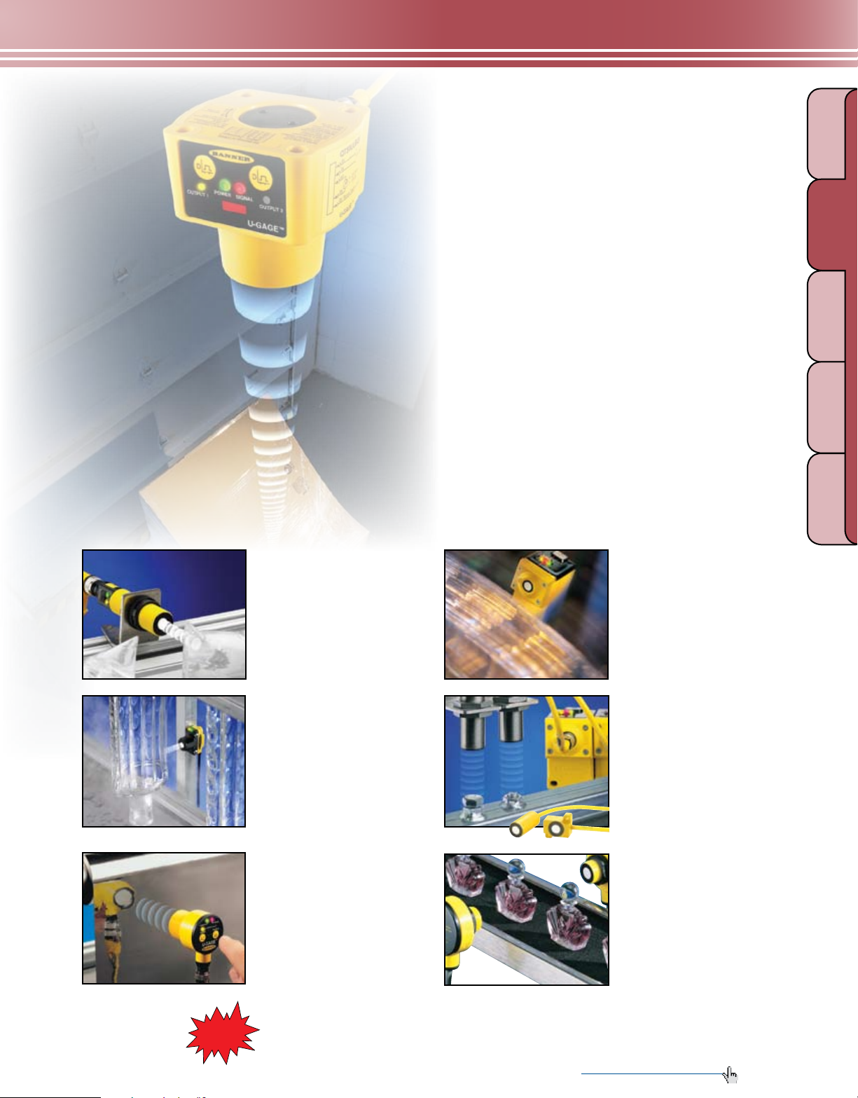
U-GAGE
®
GAUGING
LIGHT
S18U page 266
• Compact 18 mm straight or
right-angle housing
• Highly accurate detection from
30 to 300 mm
• Wide range of mounting options
Ultrasonic Sensors
QT50U page 262
• Long-range ac or dc sensor covers 8 m, with minimal
dead zone.
• Advanced programming capability includes a unique
temperature compensation feature.
• Retrosonic mode has reduced dead zone.
• Each output has two independent near and far limits.
• Optional Teflon
®
coating resists harsh chemicals.
Q45U page 276
• Operating window limits from
100 mm to 3 m
• Discrete output models for ON/OFF
presence detection or HIGH/LOW
level control
• Programmable response time
ULTRASONIC
MEASURING LIGHT
SCREENS
TEMPERATURE
RADAR
Teflon® is a registered
trademark of Dupont
QS18U page 269
• Compact 18 mm universal housing
• Compensation for air temperature
fluctuations
• Optional encapsulation for
resistance to harsh chemicals
(IP68)
T30U page 272
• Right-angle T-style housing with
30 mm threaded lens
• Analog and discrete outputs in
the same sensor
• Programmable sensing windows
with 150 mm to 1 m range or
300 mm to 2 m range
• Optional Teflon
™
.
Coming
Soon!
resistance to harsh chemicals
T30U models with temperature
compensation, longer sensing
ranges, shorter dead zones and
improved linearity.
®
coating for
More information online at bannerengineering.com
Q45UR page 280
• Ultra-accurate remote gauging
• Compact housing with choice of
three remote sensing heads
• Compensation for temperature
variations at remote head
T18U page 284
• Dual range, opposed ultrasonic sensors
• Two combinations of range and
response time in the same unit
• Ideal for sensing under bright
lighting and for clear materials
• T-style sensor with 18 mm threaded lens
261
Page 20
LIGHT
BRACKETS
QD CABLES
ULTRASONIC
MEASURING LIGHT
TEMPERATURE
GAUGING
SLOT & LABEL
SCREENS
COLOR &
PICK-TO -LIGH T
MEASUREMENT & INSPECTION
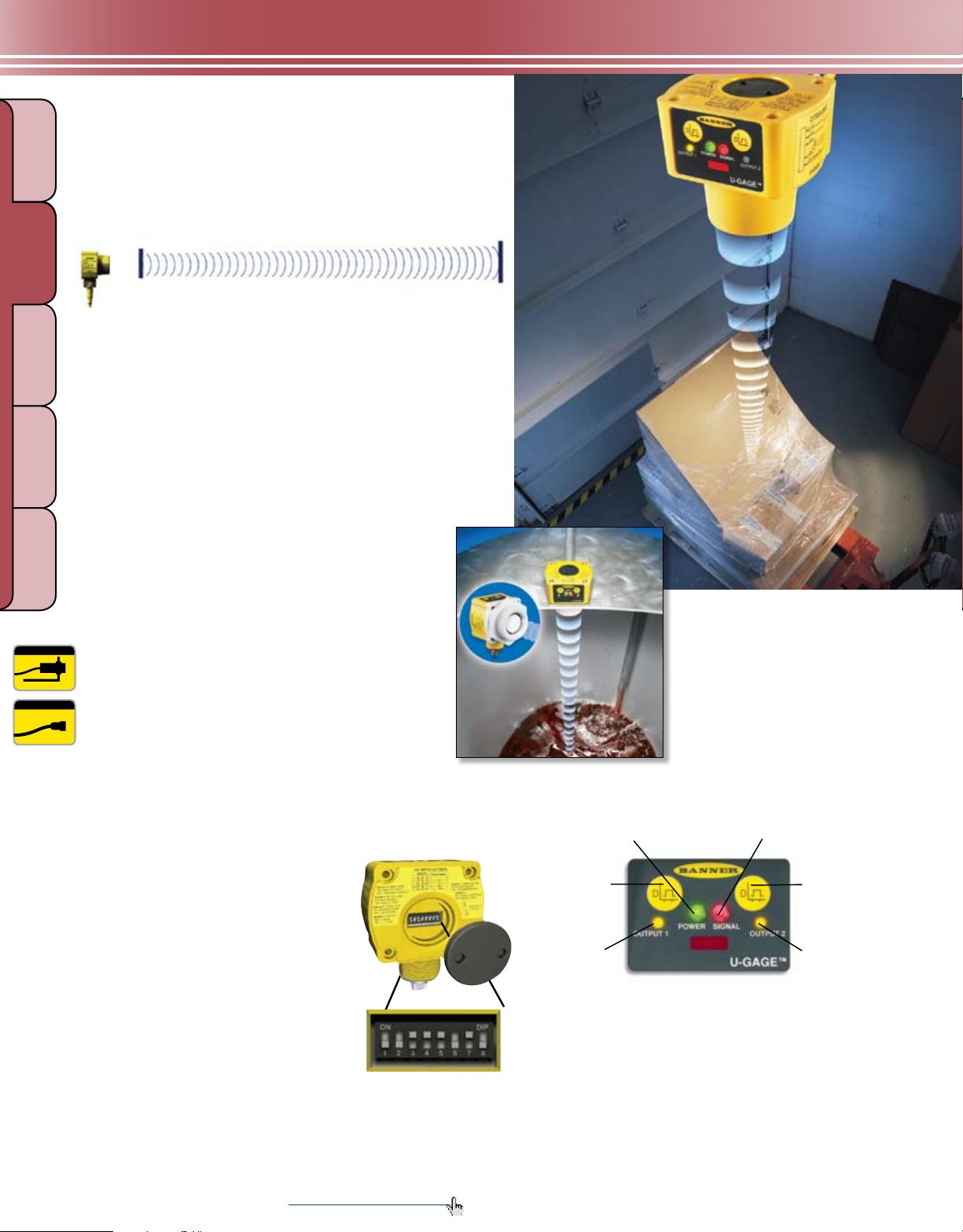
U-GAGE® QT50U
Long-range
Ultrasonic Sensor
Dead
Zone
200 mm
Minimum Range
Enhanced long-range sensing
• Senses extended range of up to 8 m
lUMINESCENCE
• Features ultrasonic dead-zone of only 2.5% of the
total range—75% less than comparable products
• Available in analog or discrete dc models and in ac/dc
universal voltage models with electromechanical relay output
• Offers retrosonic sensing mode
8 m
Maximum Range
RADAR
PAGE 372
5-Pin Euro + 5-Pin Micro
+ 5-Pin Mini
PAGE 415, 419 & 421
Designed for challenging applications
• Features a completely sealed, shock-resistant
housing that is ideal for monitoring levels of
liquids as well as solids
• Uses a narrow sensing beam to detect targets at
long range within confined areas—such as a
storage tank—without interference from
the tank walls
• Available in a chemically resistant model with a
Teflon
®
coating to protect the transducer
• Provides continuous monitoring (analog model)
• Offers dual-discrete option for setting independent
near and far limits for both outputs, for applications
requiring high and low-limit sensing
Engineered for flexibility
• Offers a multitude of configurations
in the same analog or discrete unit,
using an advanced microprocessor
and 8 DIP switches (dc models only)
• Compensates for temperature, for
greatest sensing accuracy
• Reduces dead zone and detects
objects of any size, shape and
orientation (retrosonic mode)
™
Teflon® is a registered trademark of Dupont
.
Chemically resistant models
Sensor Power
Indicator
Output 1
Push Button
Output 1
Indicator
Push-button programming
• Simplifies setup with push-button and remote
TEACH-mode programming
• Shows status during setup and operation,
using highly visible LEDs indicators
* Discrete dc model shown.
Target Signal
Strength Indicator
Output 2
Push Button
Output 2
Indicator
262 More information online at bannerengineering.com
Page 21

MEASUREMENT & INSPECTION
Detailed
Dimension
s
Dow nlo a
d
PDF
Dow nlo a
d
PDF
74.1 mm
73.1 mm
85.2 mm
M56 x 1.5
U-GAGE® QT50U Sensors
Push-button TEACH programming for
easy setup
Rugged encapsulated design for
harsh environments
Cabled or quick-disconnect models
Bright LED status indicators for
setup and operation
QD cables with shield, ordered separately
(see pages 415, 419 and 421)
74.1 mm
DC and Universal Voltage Models
67.4 mm
84.2 mm
®
Teflon
-protected Models
(Suffix -CRFV)
GAUGING
LIGHT
ULTRASONIC
MEASURING LIGHT
SCREENS
TEMPERATURE
RADAR
U-GAGE
®
QT50U, 10-30V dc
Models* Range Cable** Output Data Sheet
QT50ULB
QT50ULBQ
QT50ULBQ6
QT50UDB
QT50UDBQ
QT50UDBQ6
U-GAGE
200 mm - 8 m
200 mm - 8 m
®
QT50U Universal Voltage, 85-264V ac/24-250V dc
2 m
5-pin Mini QD
5-pin Euro QD
2 m
5-pin Mini QD
5-pin Euro QD
Selectable:
0 to 10V dc
or 4 to 20 mA
Selectable
Dual NPN
or PNP
70137
110 112
Output
Models* Range Cable*
QT50UVR3W
QT50UVR3WQ1
200 mm - 8 m
QT50UVR3WQ
QT50UVR3F
QT50UVR3FQ1
200 mm - 8 m
QT50UVR3FQ
* For sensors with Teflon®-protected face and transducer, add suffix -CRF V to the model number (example, QT50ULB-CRFV). See data sheet par t number 122155 for additional info.
** For 9 m cable, add suff ix W/30 to the 2 m model number (example, QT50ULB W/30). A model with a QD requires a mating cable (see pages 415, 419 and 421).
2 m
5-pin Micro QD
5-pin Mini QD
2 m
5-pin Micro QD
5-pin Mini QD
Operation Mode Output Data Sheet
Window-limit
(complementary
outputs)
Pump/level control
(pump-in and
pump-out logic)
SPDT
e/m relay
SPDT
e/m relay
117764
117764
Teflon® is a registered trademark of Dupont
™
.
More information online at bannerengineering.com
263
Page 22

LIGHT
ULTRASONIC
MEASURING LIGHT
TEMPERATURE
RADAR
GAUGING
SLOT & LABEL
SCREENS
COLOR &
PICK-TO -LIGH T
MEASUREMENT & INSPECTION
Effective Beam
Supply Voltage and Current
Ultrasonic Frequency
Supply Protection Circuitry
Output Protection
Delay at Power-up
Output Configuration
Output Ratings
lUMINESCENCE
Temperature Effect
Linearity (Analog Models)
Resolution/Repeatability
Hysteresis
Output Response Time
Minimum Window Size
Adjustments
Indicators
Remote TEACH
Construction
Environmental Rating
Connections
Operating Conditions
Vibration and
Mechanical Shock
Temperature Warmup Drift
Application Notes
U-GAGE® QT50U DC Specifications
See charts EBPC-1, EBPC-2 and EBPC-3 on page 513.
Analog models: 10 - 30V dc (10% max. ripple); 100 mA max @ 10V, 40 mA max. @ 30V (exclusive of load)
Dual-discrete models: 10 to 30V dc (10% max. ripple); 100 mA max. @ 10V,
40 mA @ 30V (exclusive of load)
75 kHz burst, rep. rate 96 milliseconds
Protected against reverse polarity and transient overvoltages
Protected against short circuit conditions
1.5 seconds
Analog models: Voltage sourcing: 0 to 10V dc Current sourcing: 4 to 20 mA
Dual-discrete models: Dual PNP or NPN, selectable using DIP switch
Analog Voltage Output: 0 to 10V dc
Minimum load resistance = 500 Ω
Minimum required supply voltage for full 0-10V output span = (
Analog Current Output: 4 to 20 mA
Maximum load resistance = 1 kΩ or (
Minimum required supply voltage for full 4-20 mA output span = 10V dc or
[(RLoad x 0.02)+5]V dc, whichever is greater. 4-20 mA output calibrated at 25° C with
250 Ω load.
Discrete Output: 150 mA max.
OFF-State leakage current: less than 5 µA
Output saturation: NPN: less than 200 mV @ 10 mA; less than 650 mV @ 150 mA
PNP: less than 1.2V @ 10 mA; less than 1.65V @ 150 mA
Uncompensated: 0.2% of distance/° C
Compensated: 0.02% of distance/° C
+/- 0.2% of span from 200 to 8000 mm; +/- 0.1% of span from 500 to 8000 mm (1 mm minimum)
1.0 mm
5 mm
Analog models: 100 to 2300 milliseconds
Dual-discrete models: 100 to 1600 milliseconds
20 mm
Sensing window limits: TEACH-Mode programming of near and far window limits may be set using
the push buttons or remotely using TEACH input.
Green Power ON LED: Indicates power is ON
Red Signal LED: Indicates target is within sensing range, and the condition of the received signal.
Teach/Output indicator (bicolor Yellow/Red):
Yellow–Target is within taught limits Yellow OFF (Discrete)–Target is outside taught window limits
Red–Sensor is in TEACH mode Yellow Flashing (Analog)–Target is outside taught window limits
See data sheet p/n 70137 (Analog) and p/n 110112 (Discrete)
Transducer: Ceramic/Epoxy composite Housing: ABS/Polycarbonate
Membrane Switch: Polyester Lightpipes: Acrylic
Leakproof design is rated IEC IP67; NEMA 6P
2 m or 9 m shielded 5-conductor (with drain) PVC jacketed attached cable, or 5-pin Euro-style
quick-disconnect or 5-pin Mini-style quick-disconnect. QD cables are ordered separately.
See pages 415 and 421.
Temperature: -20° to +70° C Relative humidity: 100%
All models meet Mil Std. 202F requirements. Method 201A (vibration: 10 to 60Hz max.,
double amplitude 0.06", maximum acceleration 10G). Also meets IEC 947-5-2 requirements: 30G 11
milliseconds duration, half sine wave
Less than 0.8% of sensing distance upon power-up with Temperature Compensation enabled
• Objects passing inside the specied near limit (200 mm ) may produce a false response
• For best accuracy, allow 30 minute warm-up before programming or operating
V supply - 5
0.02
) Ω, whichever is lower
1000
RLOAD
+ 13)V dc
More on
next page
264 More information online at bannerengineering.com
Page 23

MEASUREMENT & INSPECTION
Certifications
Hookup Diagrams
U-GAGE
Effective Beam
Supply Voltage
Ultrasonic Frequency
Supply Protection
Circuitry
Output Protection
Delay at Power-up
Output Configuration
Output Ratings
Temperature Effect
Repeatability
Hysteresis
Output Response Time
Minimum Window Size
Adjustments
Indicators
Construction
Environmental Rating
Connections
Operating Conditions
Vibration and
Mechanical Shock
Temperature Warmup Drift
Application Notes
Certifications
Hookup Diagrams
Teflon® is a registered trademark of Dupont
U-GAGE® QT50U DC Specifications
Analog Models: MI11 (p. 534) Discrete Models: MI10 (p. 534)
®
QT50U Universal Voltage Specifications
See charts EBPC-1, EBPC-2 and EBPC-3 on page 513.
85 to 264V ac, 50/60 Hz / 24 to 250V dc (1.5 watts max., exclusive of load)
75 kHz burst, rep. rate 96 milliseconds.
Protected against transient over voltages. DC hookup is without regard to polarity.
Protected against short circuit conditions
1.5 seconds
SPDT (Single-Pole, Double-Throw) electromechanical relay output.
One normally open (NO) and one normally closed (NC).
Max. switching power (resistive load): 2000 VA, 240 W (1000 VA, 120 W for sensors with Micro QD)
Max. switching voltage (resistive load): 250V ac, 125V dc
Max. switching current (resistive load): 8A @ 250V ac, 8A @ 30V dc derated to 200 mA @ 125V dc
(4A max. for sensors with Micro QD)
Min. voltage and current: 5V dc, 10 mA
Mechanical life of relay: 50,000,000 operations
Electrical life of relay at full resistive load: 100,000 operations
NOTE: Transient suppression is recommended when switching inductive loads.
Uncompensated: 0.2% of distance/° C Compensated: 0.02% of distance/° C
1.0 mm
Window-limit sensor models: 5 mm Fill-level control sensor models: 0 mm
Selectable 1600, 400 or 100 milliseconds
20 mm
Sensing limits: TEACH-Mode programming of near and far limits may be set using the TEACH push button.
Sensor configuration: Output response time and temperature compensation mode may be set using
the Speed push button.
Factory default settings: 400 milliseconds output response time; temperature compensation enabled
Green Power ON LED: Indicates power is ON
Red Signal LED: Indicates target is within sensing range, and the condition of the received signal.
Output indicator (bicolor Yellow/Red): Indicates output status or TEACH mode
Response indicator (bicolor Yellow/Red): Indicates output response time selection
Transducer: Ceramic/Epoxy composite Housing: ABS
Membrane Switch: Polyester
Leakproof design is rated IEC IP67; NEMA 6P
2 m or 9 m shielded 5-conductor (with drain) PVC jacketed attached cable, or 5-pin Micro-style
quick-disconnect or 5-pin Mini-style quick-disconnect. QD cables are ordered separately.
See pages 419 and 421.
Temperature: -20° to +70° C Relative humidity: 100%
All models meet Mil Std. 202F requirements. Method 201A (vibration: 10 to 60Hz max.,
double amplitude 0.06", maximum acceleration 10G). Also meets IEC 947-5-2 requirements: 30G
11 milliseconds duration, half sine wave
Less than 1.0% of sensing distance upon power-up with Temperature Compensation enabled
Objects passing inside the specied minimum sensing distance (200 mm) may produce a false response.
Contact factory for more information.
UN05 (p. 529)
™
More information online at bannerengineering.com
(cont’d)
265
GAUGING
LIGHT
ULTRASONIC
MEASURING LIGHT
SCREENS
TEMPERATURE
RADAR
Page 24

LIGHT
BRACKETS
QD CABLES
ULTRASONIC
MEASURING LIGHT
TEMPERATURE
RADAR
GAUGING
SLOT & LABEL
SCREENS
COLOR &
PICK-TO -LIGH T
MEASUREMENT & INSPECTION
U-GAGE® S18U
Compact
Ultrasonic Sensor
On-board diagnostics
®
The highly accurate U-GAGE
rst compact ultrasonic sensor with push-button TEACH
programming and diagnostic LEDs integrated right into the
housing. The S18U small size doesn’t limit its accuracy. It is
unaffected by target color and has all the features of much
larger sensors:
lUMINESCENCE
• Integrated diagnostic LEDs and push-button
programming
• Minimal dead zone
• Retrosonic sensing mode
• Temperature compensation circuitry
• Programmable background
suppression
• Analog and discrete versions
S18U is the industry’s
5-Pin Euro
PAGE 373
PAGE 415
Two housing styles
• Available in straight or right-angle versions with a
wide variety of mounting hardware for enhanced
sensing versatility
• Ideal for material handling and packaged goods
applications, such as bottling or liquid level detection
and control for small containers
• Senses from 30 to 300 mm
Straight Right Angle
Accessory wave guides are available
for narrowing sensing beam.
(see page 445)
Integrated push-button programming
Program the unit with its integrated TEACH-mode push
button or remote TEACH wire. Bright LEDs indicate status
during setup and offer visual diagnostics during operation.
Congure a set sensing window, background suppressed
sensing or retrosonic mode for detecting any object
regardless of shape, angle or size.
Power/Signal Strength
TEACH Push
Button
Output/TEACH Indicator
266 More information online at bannerengineering.com
Page 25

MEASUREMENT & INSPECTION
Detailed
Dimension
s
18.0 mm
85.1 mm
Dow nlo a
d
PDF
U-GAGE® S18U Sensors
Push-button TEACH programming for easy setup
18 mm threaded barrel housing
Straight or right-angle housing
Rugged encapsulated design for
harsh environments
Bright diagnostic LEDs on sensor housing
5-pin Euro-style QD cables with shield,
ordered separately (see page 415)
Optional wave guides for narrowing
sensing beam (see page 444)
U-GAGE
S18UUA
S18UUAQ
S18UIA
S18UIAQ
S18UUAR
S18UUARQ
S18UIAR
S18UIARQ
S18UBA
S18UBAQ
S18UBAR
S18UBARQ
®
S18U, 10-30V dc
Models Range Cable* Output
2 m
30 - 300 mm
30 - 300 mm
30 - 300 mm
5-pin Euro QD
2 m
5-pin Euro QD
2 m
5-pin Euro QD
2 m
5-pin Euro QD
2 m
5-pin Euro QD
2 m
5-pin Euro QD
Straight Models
0 to 10V dc
4 to 20 mA
0 to 10V dc
4 to 20 mA
Bipolar
NPN/PNP
80.8 mm
Configuration
S18U Right-angle Models
18.0 mm
Housing
Straight
Right-Angle
Straight
Right-Angle
Data
Sheet
110738
110738
108964
GAUGING
LIGHT
ULTRASONIC
MEASURING LIGHT
SCREENS
TEMPERATURE
RADAR
* For 9 m cable, add suffix W/30 to the 2 m model number (example, S18UUA W/30). A model with a QD requires a mating cable (see page 415).
U-GAGE® S18U Specifications
Effective Beam
Supply Voltage and Current
Ultrasonic Frequency
Supply Protection Circuitry
Output Protection
See charts EBPC-4 and EBPC-5 on page 513.
10 to 30V dc (10% max. ripple); 65 mA max. (exclusive of load), 40 mA typical @ 25V input
300 kHz, rep. rate 2.5 milliseconds
Protected against reverse polarity and transient voltages
Protected against short circuit conditions
More information online at bannerengineering.com
More on
next page
267
Page 26

LIGHT
ULTRASONIC
MEASURING LIGHT
TEMPERATURE
GAUGING
SLOT & LABEL
SCREENS
COLOR &
PICK-TO -LIGH T
MEASUREMENT & INSPECTION
Output Ratings
Output Configuration
Output Response Time
lUMINESCENCE
Delay at Power-up
Linearity*
(Analog output models)
Resolution*
(Analog output models)
Repeatability
U-GAGE® S18U Specifications (cont’d)
Analog:
Analog Voltage Output: 2.5 kΩ min. load resistance
Minimum supply for a full 10V output is 12V dc (for supply voltages
between 10 and 12, V out max is at least V supply -2)
Analog Current Output: 1 kΩ max @ 24V input
Max load resistance = (Vcc-4)/0.02 Ω
Discrete: 100 mA max.
OFF-state leakage current: less than 5 µA
NPN saturation: less than 200 mV @ 10 mA and less than 600 mV @ 100 mA
PNP saturation: less than 1.2V @ 10 mA and less than 1.6V @ 100 mA
Analog: 0 to 10V dc or 4 to 20 mA, depending on model
Discrete: Bipolar: One NPN (current sinking) and one PNP (current sourcing) output in each model.
Solid-state switch conducts when target is sensed within sensing window.
Analog: 30 milliseconds: Black wire at 0-2V dc (or open) Discrete: 5 milliseconds
2.5 milliseconds: Black wire at 5-30V dc
300 milliseconds
2.5 milliseconds response: ± 1 mm
30 milliseconds response: ± 0.5 mm
2.5 milliseconds response: 1 mm
30 milliseconds response: 0.5 mm
0.5 mm
Temperature Effect
RADAR
Temperature Warmup Drift
Minimum Window Size
Switching Hysteresis
(Discrete output models)
Adjustments
Indicators
Remote TEACH Input
Construction
Environmental Rating
Connections
Operating Conditions
Vibration and
Mechanical Shock
Application Notes
0.02% of distance/ ° C
Less than 1.7% of sensing distance upon power-up
5 mm
0.7 mm
Sensing window limits: TEACH-Mode programming of near and far window limits may be set using
the push-button or remotely using TEACH input.
Power/Signal Strength (Red/Green)
Green—Target is within sensing range
Red—Target is outside sensing range
OFF—Sensing power is OFF
TEACH/Output Indicator (Yellow/Red)
Yellow —Target is within taught limits
OFF—Target is outside taught window limits
Red—Sensor is in TEACH mode
Impedance: 12 kΩ
Threaded Barrel: Thermoplastic polyester Push-Button Housing: ABS/PC
Push Button: Santoprene Lightpipes: Acrylic
Leakproof design is rated IEC IP67; NEMA 6P
2 m or 9 m shielded 5-conductor (with drain) PVC jacketed attached cable, or 5-pin Euro-style
quick-disconnect. QD cables are ordered separately. See page 415.
Temperature: -20° to +60° C Relative humidity: 100%
All models meet Mil. Std. 202F requirements. method 201A (vibration: 10 to 60 Hz max.,
double amplitude 0.06”, maximum acceleration 10G). Also meets IEC 947-5-2 requirements: 30G
11 milliseconds duration, half sine wave
Objects passing inside the specied near limit may produce a false response.
Certifications
Hookup Diagrams
Analog Models: MI13 (p. 535) Discrete Models: MI12 (p. 534)
*Linearity and resolution are specified using a 50 x 50 mm aluminum plate at 22° C under fixed sensing conditions.
268 More information online at bannerengineering.com
Page 27

MEASUREMENT & INSPECTION
BRACKETS
QD CABLES
QS18U
Ultrasonic
®
WORLD-BEAM
• Senses clear or transparent material and color variations
• Senses within a 50 to 500 mm window with a
15 millisecond response time
• Delivers high accuracy in wet or dirty environments
• Available in encapsulated IP68 models rated for a
range of harsh conditions
• Features push-button TEACH for easy programming at
the sensor or remotely
Features
• TEACH setup using on-board push-button or remote wire
• 2 m or 9 m integral cable, 4-pin Euro- or Pico-style
integral quick-disconnect, or 150 mm threaded pigtail
QD cable options
• Wide operating range of -20° to 60° C
• Retrosonic sensing mode
Sensor
GAUGING
LIGHT
ULTRASONIC
MEASURING LIGHT
SCREENS
TEMPERATURE
RADAR
Applications
• Sense clear web materials in confined areas
• Detect clear or shiny bottles in a filling line
• Detect highly reflective surfaces
• Verify liquid or dry bulk levels from inside
cramped locations
Choice of pre-wired cable, Pico- or
Euro-style integral QD connector,
or pigtail QD (not shown)
Accessory wave guides are
available for narrowing sensing
beam. (see page 444.)
Simple push-button
programming
Rugged,
ultra-compact
housing
Bright LED bicolor operating status
indicators visible from 360°
Universal 18 mm
threaded nose or side
mounting formats
PAGE 373
4-Pin Euro +
4-Pin Pico
PAGE 411 & 412
More information online at bannerengineering.com
269
Page 28

MEASUREMENT & INSPECTION
Detailed
Dimension
s
Dow nlo a
d
PDF
LIGHT
ULTRASONIC
MEASURING LIGHT
TEMPERATURE
RADAR
GAUGING
SLOT & LABEL
SCREENS
COLOR &
PICK-TO -LIGH T
WORLD-BEAM® QS18U Sensors
Bicolor LED indicator for power and signal strength
Bicolor LED indicator for TEACH/output
Choice of cables and connectors
Rugged, ultra-compact housing
4-pin Pico- or Euro-style QD cables with shield
ordered separately (see pages 411 and 412)
lUMINESCENCE
Optional wave guides for narrowing
sensing beam (see page 444)
WORLD-BEAM® QS18U, 12-30V dc
Model Range Cable*
41.5 mm
15.0 mm
33.5 mm
TEACH
Options Output
Data
Sheet
QS18UNA
2 m
NPN
QS18UNAQ8 4-pin Euro QD
50 - 500 mm
QS18UPA 2 m
Integral push button
and remote TEACH
(IP67; NEMA 6P)
PNP
QS18UPAQ8 4-pin Euro QD
QS18UNAE
QS18UNAEQ8
QS18UPAE
QS18UPAEQ8
* For 9 m cable, add suffix W/30 to the 2 m model number (example, QS18UNA W/30). A model with a QD requires a mating cable (see pages 411 and 412).
QD mod els:
• For 4-pin integral Euro-style QD, add suffix Q8 (example, QS18UNAQ8). • For 4-pin 150 mm Euro-style pigtail, add suff ix Q5 (example, QS18UNAQ5).
• For 4-pin integral Pico-style QD, add suffix Q7 (example, QS18UNAQ7). • For 4-pin 150 mm Pico-st yle pigtail, add suf fix Q (example, QS18UNAFQ).
†
Models are epoxy-encapsulated, IP68; NEMA 6P with remote TEACH programming
†
†
†
†
50 - 500 mm
2 m
4-pin Euro QD
2 m
4-pin Euro QD
NPN
Remote TEACH
(epoxy-encapsulated,
IP68; NEMA 6P)
PNP
119287
119287
270 More information online at bannerengineering.com
Page 29

Sensing Range
Sensing Beam
Supply Voltage
Ultrasonic Frequency
Supply Protection Circuitry
Output Protection
Delay at Power-Up
Output Configurations
Temperature Effect
Repeatability
Hysteresis
Output Ratings
Output Response Time
Minimum Window Size
Adjustments
Indicators
Construction
Environmental Rating
Connections
Operating Conditions
Vibration and Mechanical
Shock
Temperature Warmup Drift
Application Notes
Certifications
Hookup Diagrams
MEASUREMENT & INSPECTION
WORLD-BEAM® QS18U Specifications
50 to 500 mm
See charts EBPC-6 and EBPC-7 on pages 513-514.
12 to 30V dc (10% max. ripple); 25 mA max. (exclusive of load)
300 kHz, rep. rate 7.5 milliseconds
Protected against reverse polarity and transient voltages
Protected against short circuit conditions
300 milliseconds
Solid-state switch conducts when target is sensed within sensing window;
One NPN (current sinking) or one PNP (current sourcing), depending on model.
Non-encapsulated models: ± 0.05% per ° C from -20° to +50° C, ± 0.1% per ° C from +50° to +60° C
Encapsulated models: ± 0.05% per ° C from 0° to +60° C, ± 0.1% per ° C from -20° to 0° C
0.7 mm
1.4 mm
100 mA max.
OFF-state leakage current: less than 10 µA (sourcing); less than 200 µA (sinking)
NPN ON-state saturation voltage: less than 1.6V @ 100 mA
PNP ON-state saturation voltage: less than 2.0V @ 100 mA
15 milliseconds
5 mm
Sensing window limits: TEACH-Mode programming of near and far window limits may be set using
the push button or remotely using TEACH input.
Range Indicator (Red/Green)
Green—Target is within sensing range
Red—Target is outside sensing range
OFF—Sensing power is OFF
Housing: ABS Push-Button Housing: ABS
Push Button: TPE Lightpipes: Polycarbonate
Leakproof design, rated IEC IP67 or IP68; NEMA 6P, depending on model
2 m or 9 m 4-conductor PVC jacketed attached cable, or 4-pin Euro-style integral QD (Q8), or 4-pin
Pico-style integral QD (Q7), or 4-pin Euro-style 150 mm pigtail QD (Q5), or 4-pin Pico-style 150 mm
pigtail QD (Q), depending on model. See pages 411 and 412.
Temperature: -20° to +60° C Relative humidity: 100% (non-condensing)
All models meet Mil. Std. 202F requirements method 201A (vibration: 10 to 60 Hz max., double
amplitude 0.06", maximum acceleration 10G). Also meets IEC 947-5-2 requirements: 30G 11
milliseconds duration, half sine wave.
See data sheet p/n
119287 for more information.
Objects passing inside the specied near limit may produce a false response.
MI14 (p. 535)
Teach/Output Indicator (Yellow/Red)
Yellow—Target is within taught limits
OFF—Target is outside taught window limits
Red—Sensor is in TEACH mode
GAUGING
LIGHT
ULTRASONIC
MEASURING LIGHT
SCREENS
TEMPERATURE
RADAR
More information online at bannerengineering.com
271
Page 30

LIGHT
BRACKETS
QD CABLES
ULTRASONIC
MEASURING LIGHT
TEMPERATURE
GAUGING
SLOT & LABEL
SCREENS
COLOR &
PICK-TO -LIGH T
MEASUREMENT & INSPECTION
U-GAGE® T30U
Compact Sensors in
Universal Housing
Incredible versatility
The U-GAGE® T30U sets new standards for ultrasonic sensor
versatility by including discrete (switched) and analog outputs
in the same compact sensor. Dual-discrete models also are
available.
Two model types
lUMINESCENCE
• Combined analog and discrete output models:
- Offers choice of either NPN or PNP
discrete output and either 0-10V dc
or 4-20 mA sourcing analog
output—in the same compact sensor
- Features outputs that are
independently configurable
PAGE 373
5-Pin Euro
PAGE 415
RADAR
• Dual-discrete output:
- Features two NPN or two PNP
discrete outputs
- Offers independently
programmable outputs
- Available in models for direct liquid
level control (pump in/pump out)
Patented, ultra-short T-shaped package
The T30U is the shortest 30 mm diameter ultrasonic sensor
available and is less than half the length of comparable
competitive sensors.
• Four LED indicators keep you constantly informed of
programming and operating status.
• Strength of ashing red LED indicates the strength of the
COMING
SOON!
Push-button TEACH-mode programming
• Features simple 3-step push-button setup for accurate,
custom sensing windows within a 150 mm to 1 m range
or a 300 mm to 2 m range
• Can be programmed from a remote location using an
external switch, computer or controller for added security
and convenience
Coming in 2008—New T30UX Models
• Longer sensing ranges: 1, 2 and 3 m
with shorter dead zones
• Built-in temperature compensation
• Improved linearity of analog output
received signal.
• Two yellow LEDs indicate the target is within the
operating window limits.
• Digital ltering provides immunity from random electrical
and acoustic noise, as well as protection from transient
voltage and reverse polarity.
®
• Optional Teon
coating protects the transducer from
harsh chemicals.
™
Teflon® is a registered trademark of Dupont
272 More information online at bannerengineering.com
.
Chemically resistant models
Page 31

MEASUREMENT & INSPECTION
Dow nlo a
d
PDF
45.0 mm
51.5 mm
ø 40.0 mm
63.7 mm
48.3 mm
Detail ed
Dimens ion
s
U-GAGE® T30U Sensors
T-style right-angle sensor package with
30 mm threaded mount
2 m or 9 m attached cable, or
quick-disconnect fitting
Easy-to-use push-button programming
LED indicators for Power, Signal and
both outputs
ø 40.0 mm
5-pin Euro-style QD cables with
shield ordered separately (see page 415)
Long-range Models
45.0 mm
51.5 mm
U-GAGE® T30U, 12-24V dc
Discrete
Models* Range Frequency Cable**
T30UINA
T30UINAQ
150 mm - 1 m 228 kHz
T30UIPA
T30UIPAQ
T30UINB
T30UINBQ
300 mm - 2 m
†
128 kHz
T30UIPB
T30UIPBQ
T30UDNA
T30UDNAQ
150 mm - 1 m 228 kHz
T30UDPA
T30UDPAQ
T30UDNB
T30UDNBQ
300 mm - 2 m
†
128 kHz
T30UDPB
T30UDPBQ
T30UHNA
150 mm - 1 m 228 kHz
T30UHNAQ
T30UHNB
300 mm - 2 m
†
128 kHz
T30UHNBQ
T30UHPA
150 mm - 1 m 228 kHz
T30UHPAQ
T30UHPB
T30UHPBQ
* For sensors with Teflon®-protected face and transducer (long-range models only), add suff ix -CRFV to the model number (example, T30UINB-CRFV).
** For 9 m cable, add suffix W/30 to the 2 m model number (example, T30UINA W/30). A model with a QD requires a mating cable (see page 415).
†
®
Tef lo n
-encapsulated models have a range of 300 - 1.5 m.
Teflon® is a registered trademark of Dupont
300 mm - 2 m
†
128 kHz
™
2 m
5-pin Euro QD
2 m
5-pin Euro QD
2 m
5-pin Euro QD
2 m
5-pin Euro QD
2 m
5-pin Euro QD
2 m
5-pin Euro QD
2 m
5-pin Euro QD
2 m
5-pin Euro QD
2 m
5-pin Euro QD
2 m
5-pin Euro QD
2 m
5-pin Euro QD
2 m
5-pin Euro QD
Output(s)
NPN
PNP
NPN
PNP
Dual NPN
Dual PNP
Dual NPN
Dual PNP
Pump/Level
Control
Dual NPN
Pump/Level
Control
Dual PNP
More information online at bannerengineering.com
Analog
Output
4 to 20
mA
4 to 20
mA
None 48 ms
None 96 ms
None
None
Short-range Models
Teflon-protected Models
Suffix -CRFV
Response
Time
48 ms
96 ms
Data
Sheet
57438
57438
59200
59200
48 ms
63974
96 ms
48 ms
63974
96 ms
273
GAUGING
LIGHT
ULTRASONIC
MEASURING LIGHT
SCREENS
TEMPERATURE
RADAR
Page 32

MEASUREMENT & INSPECTION
Dow nlo a
d
PDF
U-GAGE® T30U, 15-24V dc
LIGHT
ULTRASONIC
MEASURING LIGHT
TEMPERATURE
RADAR
GAUGING
SLOT & LABEL
SCREENS
COLOR &
PICK-TO -LIGH T
Discrete
Models* Range Frequency Cable**
T30UUNA
T30UUNAQ
150 mm - 1 m 228 kHz
T30UUPA
T30UUPAQ
T30UUNB
T30UUNBQ
300 mm - 2 m
†
128 kHz
T30UUPB
T30UUPBQ
lUMINESCENCE
* For sensors with Teflon®-protected face and transducer (long-range models only), add suffix - CRFV to the model number (example, T30UUNB-CRFV).
** For 9 m cable, add suffix W/30 to the 2 m model number (example, T30UUNA W/30). A model with a QD requires a mating cable (see page 415).
†
Te flo n®-encapsulated models have a range of 300 - 1.5 m.
2 m
5-pin Euro QD
2 m
5-pin Euro QD
2 m
5-pin Euro QD
2 m
5-pin Euro QD
Output(s)
NPN
PNP
NPN
PNP
Analog
Output
0 to 10V dc 48 ms
0 to 10V dc
U-GAGE® T30U Specifications
Sensing Range
Effective Beam
Supply Voltage
Ultrasonic Frequency
Supply Protection Circuitry
“A” suffix models: 150 mm min. near limit; 1 m max. far limit
“B” suffix models: 300 mm min. near limit; 2 m max. far limit
“-CRFV” models: 300 mm min. near limit; 1.5 m max. far limit
See charts EBPC-8, EBPC-9, EBPC-10, EBPC-11 and EBPC-12 on page 514.
Current sourcing analog output models: 12 to 24V dc (10% max. ripple); 90 mA (exclusive of load)
Voltage sourcing analog output models: 15 to 24V dc (10% max. ripple); 90 mA (exclusive of load)
Dual-discrete output models: 12 to 24V dc (10% max. ripple); 90 mA (exclusive of load)
Short Range: 228 kHz
Long Range: 128 kHz
Protected against reverse polarity and transient voltages.
Response
Time
96 ms
Data
Sheet
57438
Output Protection
Output Configuration
Output Ratings
Output Response Time
Teflon® is a registered trademark of Dupont™
Protected against continuous overload and short-circuit; transient over-voltage; no false pulse on power-up.
Discrete (switched) output: Solid-state switch conducts when target is sensed within sensing window;
choose NPN (current sinking) or PNP (current sourcing) models.
Analog output: Choose 0 to 10V dc sourcing or 4 to 20 mA sourcing output models;
output slope may be selected using TEACH sequence.
Discrete (switched) output: 100 mA max., total–both outputs
OFF-state leakage current: less than 10 µA
ON-state saturation voltage: less than 1V at 10 mA and less than 1.5V at 100 mA
Analog Output:
Voltage sourcing: 0 to 10V dc (at 1 kΩ min. resistance)
Current sourcing: 4 to 20 mA, 1 Ω to Rmax.
Rmax = V
supply
20 mA
- 7V
Discrete output: “A” suffix models: 48 milliseconds
“B” suffix models: 96 milliseconds
Analog output: “A” suffix models: 48 milliseconds average, 16-millisecond update
“B” suffix models: 96 milliseconds average, 32-millisecond update
.
More on
next page
274 More information online at bannerengineering.com
Page 33

Sensing Performance
(Specied using a 100 x
100 mm aluminum target at
25˚ C under xed sensing
conditions.)
Adjustments
Indicators
Construction
Environmental Rating
Connections
Operating Conditions
Vibration and
Mechanical Shock
Application Notes
Certifications
MEASUREMENT & INSPECTION
U-GAGE® T30U Specifications
Analog sensing resolution or discrete output repeatability: ±0.25% of measured distance
“A” suffix models: .5 mm min
“B” suffix models: 1 mm min
Analog linearity: ±0.5% of full-scale span
Min. window size: 10 mm
Hysteresis of discrete output: 2.5 mm
Temperature effect: 0.2% of sensing distance per ° C
Sensing window limits (analog or discrete): TEACH-mode programming of near and far window
limits may be set using membrane push buttons on sensor or remotely using TEACH input. Window
limits may be programmed separately, or together.
Analog output slope: the rst limit taught is assigned to the minimum output value (4 mA or 0V).
Four status LEDs: In RUN mode:
Green ON Steady: Power ON, RUN mode
Green Flashing: Discrete output is overloaded
Red Flashing: Relative received signal strength
Yellow analog ON Steady: Target is inside window limits
Yellow discrete ON Steady: Output conducting
In Program mode:
Green OFF: PROGRAM mode
Red Flashing: Relative received signal strength
Yellow ON Steady: Ready for rst window limit
Yellow Flashing: Ready for second limit
Yellow OFF: Not teaching this output
Molded reinforced thermoplastic polyester housing.
Leakproof design is rated IEC IP67; NEMA 6P
2 m or 9 m 5-conductor PVC-covered attached cable, or 5-pin Euro-style quick-disconnect tting.
QD cables are ordered separately. See page 415.
Temperature: -20° to +70° C Relative humidity: 100%
All models meet Mil. Std. 202F requirements. Method 201A (Vibration: 10 to 60Hz max., double
amplitude 0.06", maximum acceleration 10G). Also meets IEC 947-5-2 requirements: 30G, 11
milliseconds duration, half sine wave.
Objects passing inside the specied near limit will produce a false response.
NOTE: For more information about out-of-range and signal loss response of the analog output,
see product literature.
(cont’d)
GAUGING
LIGHT
ULTRASONIC
MEASURING LIGHT
SCREENS
TEMPERATURE
RADAR
Hookup Diagrams
Analog/Discrete Models: MI16 (p. 535)
Dual-Discrete Models: MI15 (p. 535)
More information online at bannerengineering.com
275
Page 34

LIGHT
QD CABLES
BRACKETS
GAUGING
ULTRASONIC
SLOT & LABEL
SCREENS
COLOR &
lUMINESCENCE
MEASURING LIGHT
TEMPERATURE
PICK-TO -LIGH T
RADAR
PAGE 373
5-Pin Euro + 5-Pin Mini
MEASUREMENT & INSPECTION
U-GAGE® Q45U
Flexible
Ultrasonic Sensors
The U-GAGE® Q45U series offers a choice of analog or
bipolar discrete models, designed for either long-range or
short-range sensing.
• Push-button TEACH programming makes it easy to set
the near/far limits of the sensing window.
• Available ranges are 100 to 1400 mm for the
short-range models and 0.25 to 3.0 m for the
long-range models.
• Bipolar discrete models have switches for ON/OFF
presence detection and HIGH/LOW level control.
- In ON/OFF mode, detects either when the target is
within the set range or when it is outside the range.
- In HIGH/LOW mode, detects when the target is
outside the configured range, for fill level control, web
tensioning control and similar applications.
• Response time is programmed with switches in discrete
models and with a potentiometer in analog models.
• For remote programming, analog models can be wired
directly to an external switch, controller or computer to
set window limits—ideal for inaccessible applications
such as roll diameter detection for overhead cranes.
PAGE 415 & 421
Program storage cards
After you set up window limits,
you can store the limits on
circuit cards with non-volatile
memory for fast setup. Just
store the settings from any Q45U
sensor on the card, and then transfer
the settings to any Q45U sensor with
the same available sensing range.
276 More information online at bannerengineering.com
Page 35

MEASUREMENT & INSPECTION
Detailed
Dimension
s
Dow nlo a
d
PDF
79.4 mm
44.5 mm
87.6 mm
Dow nlo a
d
PDF
U-GAGE® Q45U Sensors
60.5 mm
5-segment target position indicator
2 m or 9 m attached cable, or
Mini- or Euro-style quick-disconnect
Three status LEDs
Simple push button for programming
limits of sensing window
5-pin Mini- or Euro-style QD cables
with shield ordered separately (see
pages 415 and 421)
Short-range Models
U-GAGE® Q45U Discrete Output, 12-24V dc
44.5 mm
87.6 mm
Long-range Models
GAUGING
LIGHT
ULTRASONIC
MEASURING LIGHT
SCREENS
TEMPERATURE
RADAR
Temperature
Models Range
Q45UBB63DA
Q45UBB63DAQ
Q45UBB63DAQ6
Q45UBB63DAC
Q45UBB63DACQ
Q45UBB63DACQ6
Q45UBB63BC
Q45UBB63BCQ
Q45UBB63BCQ6
100 mm - 1.4 m
250 mm - 3 m
Compensation Cable*
No
Yes
†
Yes
5-pin Mini QD
5-pin Euro QD
5-pin Mini QD
5-pin Euro QD
5-pin Mini QD
5-pin Euro QD
U-GAGE® Q45U Analog Output, 15-24V dc
Temperature
Models Range
Q45ULIU64ACR
Q45ULIU64ACRQ
Q45ULIU64ACRQ6
Q45ULIU64BCR
Q45ULIU64BCRQ
Q45ULIU64BCRQ6
100 mm - 1.4 m Yes
250 mm - 3 m
Compensation Cable*
5-pin Mini QD
5-pin Euro QD
†
Yes
5-pin Mini QD
5-pin Euro QD
2 m
2 m
2 m
2 m
2 m
Output
Type
Bipolar
NPN/PNP
Bipolar
NPN/PNP
Output
Type
Selectable
0 to 10V dc
or
4 to 20 mA
Response
Time
Programmable for
20, 40, 160,
or 640 ms
Programmable for
40, 80, 320,
or 1280 ms
Response
Time
Adjustable from
40 to 1280 ms
Adjustable from
80 to 2560 ms
Data
Sheet
44177
48454
Data
Sheet
47818
48456
* For 9 m cable, add suffix W/30 to the 2 m model number (example, Q45UBB63DA W/30). A model with a QD requires a mating cable (see pages 415 and 421).
†
The far limit may be extended as far as 3.9 m for good acoustical targets–hard surfac es with area greater than 100 cm2.
More information online at bannerengineering.com
277
Page 36

MEASUREMENT & INSPECTION
U-GAGE® Q45U Specifications
Sensing Range
LIGHT
GAUGING
Near limit: 100 mm min. Long Range: Near limit: 250 mm min.
Far limit: 1.4 m max. Long Range: Far limit: 3.0 m max.
NOTE: The far limit may be extended on long range units, as far as 3.9 m for good acoustical targets
(hard surfaces with area greater than 100 cm2)
ULTRASONIC
MEASURING LIGHT
TEMPERATURE
RADAR
SLOT & LABEL
SCREENS
COLOR &
PICK-TO -LIGH T
Supply Voltage and Current
Ultrasonic Frequency
Supply Protection Circuitry
Output Protection Circuitry
Output Configuration
lUMINESCENCE
Output Ratings
Performance Specifications
Response Curves
Adjustments
Indicators
Discrete: 12 to 24V dc (10% max. ripple); 100 mA (exclusive of load)
Analog: 15 to 24V dc (10% max. ripple); 100 mA (exclusive of load)
Long Range: 128 kHz Short Range: 230 kHz
Protected against reverse polarity and transient voltages.
Protected against false pulse on power-up and continuous overload or short-circuit of outputs.
Discrete: Bipolar: One current sourcing (PNP) and one current sinking (NPN) open-collector transistor.
Analog: One voltage sourcing and one current sourcing; one or the other output is enabled by internal
programming switch #2.
Discrete: 150 mA max. (each)
OFF-state leakage current: less than 25 µA at 24V dc
ON-state saturation voltage: less than 1.5V at 10 mA; less than 2.0V at 150 mA
Analog: Voltage sourcing: 0 to 10V dc, 10 mA max.
Current sourcing: 4 to 20 mA, 1 to 500 Ω impedance
Short Range Long Range
Analog resolution or
discrete repeatability: ± 0.1% of sensing distance ± 0.1% of sensing distance
(± 0.25 mm min.) (± 0.5 mm min.)
Analog Linearity: 1% of full scale 1% of full scale
Temperature effect: 0.05% of sensing distance/ ° C with temp. comp. 0.05% of sensing distance/° C
0.2% of sensing distance/ ° C without temp. comp.
Min. window size: 10 mm 25 mm
Hysteresis (discrete output): 5 mm 10 mm
Short Range: See charts RC-2 and RC-4 on page 516.
Long Range: See charts RC-3 and RC-5 on page 516.
The following may be selected by a 4-position DIP switch located on top of the sensor, beneath a
transparent o-ring sealed acrylic cover:
Discrete: Switch 1: Output normally open/normally closed (pump in/pump out)
Switch 2: High/Low level control mode or ON/OFF presence sensing mode
Switch 3 & 4: Response speed selection (digital lter)
Analog: Switch 1: Output slope positive or output slope negative
Switch 2: Current output mode or voltage output mode
Switch 3: Loss of echo min/max mode or loss of echo Hold Mode
Switch 4: Loss of echo min/max default output value
Discrete: Three status LEDs:
Green ON steady: power to sensor is ON
Green flashing: output is overloaded
Yellow ON steady: outputs are conducting (Yellow LED also indicates programming
status during setup mode)
Red flashing: indicates relative strength of received echo
Analog: Three status LEDs:
Green ON steady: power to sensor is ON
Green flashing: current output fault detected (the 4-20 mA current path to ground has
Yellow ON steady: target is sensed within the window limits (Yellow LED also indicates
Red flashing: indicates relative strength of received echo
5-segment moving dot LED indicates the position of the target within the sensing window.
278 More information online at bannerengineering.com
been opened)
programming status during setup mode)
More on
next page
Page 37

MEASUREMENT & INSPECTION
Construction
Environmental Rating
Connections
Operating Conditions
Vibration and
Mechanical Shock
Application Notes
Certifications
Hookup Diagrams
U-GAGE® Q45U Specifications
Molded PBT polyester thermoplastic polyester housing, o-ring sealed transparent acrylic top cover, and
stainless steel hardware. Q45U sensors are designed to withstand 1200 psi washdown. The base of
cabled models has a ½"-14NPS internal conduit thread.
Leakproof design is rated IEC IP67; NEMA 6P
2 m or 9 m attached cable, or 5-pin Mini-style or 5-pin Euro-style QD fitting. QD cables are ordered
separately. See pages 415 and 421.
Temperature: -25° to +70° C Relative humidity: 100%
All models meet Mil. Std. 202F requirements. Method 201A (Vibration: 10 to 60Hz max., double
amplitude 0.06", maximum acceleration 10G). Method 213B conditions H & I (Shock: 75G with unit
operating; 100G for non-operation). Also meets IEC 947-5-2 requirements: 30G, 11 milliseconds
duration, half sine wave.
Short Range: Min. target size: 10 x 10 mm aluminum plate at 500 mm
35 x 35 mm aluminum plate at 1.4 m
Long Range: Min. target size: 50 x 50 mm aluminum plate at 3 m
Discrete: Enable/Disable; Connect yellow wire to +5 to 24V dc to enable sensor and 0 to +2V dc to
disable sensor. When the sensor is disabled, the last output state is held until the sensor is re-enabled.
The wire must be held to the appropriate voltage for at least 40 milliseconds for the sensor to enable
or disable.
MI17 (p. 536)
(cont’d)
GAUGING
LIGHT
ULTRASONIC
MEASURING LIGHT
SCREENS
TEMPERATURE
RADAR
More information online at bannerengineering.com
279
Page 38

LIGHT
BRACKETS
QD CABLES
ULTRASONIC
MEASURING LIGHT
TEMPERATURE
GAUGING
SLOT & LABEL
SCREENS
COLOR &
PICK-TO -LIGH T
MEASUREMENT & INSPECTION
U-GAGE® Q45UR
Remote Ultrasonic Sensors
Precise sensing for hard-to-access or difficult applications
The U-GAGE
available with analog or bipolar discrete output. They offer the
same advanced features as standard Q45U models, with the
additional choice of three remote sensing heads for use in
conned or difcult environments.
• Sensing head choices are 18 mm diameter threaded
barrel housing in plastic or stainless steel, or ultra compact plastic Flat-Pak.
lUMINESCENCE
• Sensing range is 50 to 250 mm.
• All models feature built-in temperature compensation
and an operating temperature range from -25° to 70° C.
• Environmental rating is IEC IP65 and NEMA 4.
• Digital filtering provides immunity from random electrical
and acoustic noise.
®
Q45UR remote ultrasonic sensors are
RADAR
PAGE 373
5-Pin Euro +
5-Pin Mini
PAGE 415 & 421
Push-button setup
Push-button TEACH-mode programming enables you
to program exact sensing ranges and sensing windows,
either by separately setting the lower and upper limits or by
selecting the midpoint of a specic sensing window.
Analog and discrete output
• Response time is programmed with switches in discrete
models and with a potentiometer in analog models.
• Adjustable response time is from 10 to 320 milliseconds
for analog output sensors and 40 or 160 milliseconds
for discrete output sensors.
• Analog models feature a selectable positive or
negative output slope.
• Resolution is 0.1 mm for analog models and
0.6 mm for bipolar discrete models.
280 More information online at bannerengineering.com
Page 39

U-GAGE® Q45UR Sensors
Detai led
Dimen sio n
s
Dow nlo a
d
PDF
27.5 mm
27.5 mm
12.0 mm
18 x 1 mm
Thread
45.0 mm
Dow nlo a
d
PDF
5-segment target position indicator
2 m or 9 m attached cable, or Mini- or
Euro-style quick-disconnect
Stainless steel barrel or plastic
threaded barrel, and Flat-Pak
transducer available
Simple push button for programming
limits of sensing window
Remote sensing heads with built in
temperature compensation
5-pin Mini- or Euro-style QD cables
with shield ordered separately
(see pages 415 and 421)
87.6 mm
44.5 mm
MEASUREMENT & INSPECTION
60.5 mm
M18C2.0 & S18C2.0
Remote Sensors
Q45UR Controllers
(S18C2.0 Remote Sensor separate)
Q13C2.0 Remote Sensors
GAUGING
LIGHT
ULTRASONIC
MEASURING LIGHT
SCREENS
TEMPERATURE
U-GAGE® Q45UR Discrete Output, 12-24V dc
Kit Includes
Kit Models
Q45UR3BA63CK Q45UR3BA63C
Q45UR3BA63CQK Q45UR3BA63CQ
Q45UR3BA63CQ6K Q45UR3BA63CQ6
Q45UR3BA63CKQ Q45UR3BA63C
Q45UR3BA63CQKQ Q45UR3BA63CQ
Q45UR3BA63CQ6KQ Q45UR3BA63CQ6
Q45UR3BA63CKS Q45UR3BA63C
Q45UR3BA63CQKS Q45UR3BA63CQ
Q45UR3BA63CQ6KS Q45UR3BA63CQ6
Controller Model
Kit Includes
Sensor Model
M18C2.0
Stainless
Steel Barrel
Q13C2.0
Flat-Pak
S18C2.0
Molded
Barrel
Sensor
Range
50 - 250 mm
50 - 250 mm
50 - 250 mm
Controller
Cable*
2 m
5-pin Mini QD
5-pin Euro QD
2 m
5-pin Mini QD
5-pin Euro QD
2 m
5-pin Mini QD
5-pin Euro QD
U-GAGE® Q45UR Analog Output, 15-24V dc
Kit Includes
Kit Models
Q45UR3LIU64CK Q45UR3LIU64C
Q45UR3LIU64CQK Q45UR3LIU64CQ
Q45UR3LIU64CQ6K Q45UR3LIU64CQ6
Q45UR3LIU64CKQ Q45UR3LIU64C
Q45UR3LIU64CQKQ Q45UR3LIU64CQ
Q45UR3LIU64CQ6KQ Q45UR3LIU64CQ6
Q45UR3LIU64CKS Q45UR3LIU64C
Q45UR3LIU64CQKS Q45UR3LIU64CQ
Q45UR3LIU64CQ6KS Q45UR3LIU64CQ6
* For 9 m cable, add suffix W/30 to 2 m model number (example, Q45UR3BA63CK W/30). A model with a QD requires a mating cable (see pages 415 and 421).
Controller Model
Kit Includes
Sensor Model
M18C2.0
Stainless
Steel Barrel
Q13C2.0
Flat-Pak
S18C2.0
Molded
Barrel
Sensor
Range
50 - 250 mm
50 - 250 mm
50 - 250 mm
More information online at bannerengineering.com
Controller
Cable*
2 m
5-pin Mini QD
5-pin Euro QD
2 m
5-pin Mini QD
5-pin Euro QD
2 m
5-pin Mini QD
5-pin Euro QD
Controller
Output
Bipolar
NPN/PNP
Bipolar
NPN/PNP
Bipolar
NPN/PNP
Controller
Output
Selectable
0 to 10V dc
or
4 to 20 mA
Data
Sheet
59321
59321
59321
Data
Sheet
59323
281
RADAR
Page 40

MEASUREMENT & INSPECTION
U-GAGE® Q45UR High-Gain Controllers
Product P/N Version
LIGHT
GAUGING
63060 Q45UR3BA63CQ6-63060
Discrete
ULTRASONIC
MEASURING LIGHT
TEMPERATURE
RADAR
SLOT & LABEL
SCREENS
COLOR &
PICK-TO -LIGH T
63667 Q45UR3LIU64CQ6-63667
NOTE: Special High-Gain controllers are available for small object detection. Contact factor y for more information.
Analog
U-GAGE® Q45UR Remote Sensors Specifications
Supply Voltage and Current
Ultrasonic Frequency
lUMINESCENCE
Supply Protection Circuitry
Output Protection Circuitry
Output Rating
Output Configuration
Performance Specifications
Discrete: 12 to 24V dc (10% max. ripple); 100 mA (exclusive of load)
Analog: 15 to 24V dc (10% max. ripple); 100 mA (exclusive of load)
400 kHz
Protected against reverse polarity and transient voltages
Both outputs are protected against continuous overload and short circuit
Discrete: 150 mA max. (each output)
OFF-state leakage current: less than 25 µA at 24V dc
ON-state saturation voltage: less than 1.5V at 10 mA; less than 2.0V at 150 mA
Analog: Voltage sourcing: 0 to 10V dc, 10 mA max.
Current sourcing: 4 to 20 mA, 1 to 500 Ω impedance
Discrete: Bipolar: One current sourcing (PNP) and one current sinking (NPN) open collector transistor
Analog: One voltage sourcing and one current sourcing; one or the other output is enabled by internal
programming switch #2
Discrete: Response Speed: 40 or 160 milliseconds (switch selectable)
Repeatability*: ±0.2% of measured distance
Temperature stability: ±0.03% of the window limit positions per ° C from 0° to 50° C
(±0.05% per ° C over remainder of operating temperature range)
Sensing window width: 5 to 200 mm, when independent near and far limits are taught; 1, 2, 3,
or 4 mm (switch selectable), when a sensing distance set point is taught
Hysteresis: 0.5 mm
Ultrasonic beam angle: ±3.5˚
Analog: Response Speed: 10 to 320 milliseconds (2 to 64 cycles) selectable
Resolution*: 0.2% of sensing distance at 320 milliseconds response
0.4% of sensing distance at 10 milliseconds response
Linearity*: 1% of full scale
Temperature stability: ±0.03% of sensing distance per ° C from 0° to 50° C
Ultrasonic beam angle: ±3.5˚
* Repeatability and analog resolution and linearity are specied using a 50 x 50 mm aluminum plate
at 22° C under xed sensing conditions (Analog: using the 4 to 20 mA output @ 15V dc)
Response Curves
Adjustments
See chart RC-6 on page 516.
Discrete: The following may be selected by a 4-position DIP switch located on top of the controller, beneath
a transparent O-ring sealed acrylic cover and beneath the black inner cover
Switch 1: Output normally open (output is energized when target is within sensing window limits),
or normally closed (output is energized when target is outside sensing window limits)
Switches 2 & 3: Sensing window size (1, 2, 3 or 4 mm)
Switch 4: Response speed selection (40 or 160 milliseconds)
Analog: Push-button TEACH-mode programming of window limits. The following may be selected by a
4-position DIP switch located on top of the controller, beneath a transparent O-ring sealed acrylic
cover and beneath the black inner cover
Switch 1: Output slope: output value increases or decreases with distance
Switch 2: Output mode: current output or voltage output
Switches 3 & 4: Response to loss of echo
Response Speed Adjustment: Single-turn potentiometer selects six response values from
10 to 320 milliseconds
282 More information online at bannerengineering.com
(±0.05% per ° C over remainder of operating temperature)
More on
next page
Page 41

MEASUREMENT & INSPECTION
Indicators
Construction
Environmental Rating
Connections
Operating Conditions
Vibration and
Mechanical Shock
Application Notes
U-GAGE® Q45UR Remote Sensors Specifications
Discrete: Three status LEDs:
Green ON steady: Power to controller is ON
Green flashing: Output is overloaded
Yellow ON steady: Output are conducting
(Yellow also indicates programming status during setup)
Red flashing: Relative strength of received echo
5-segment moving dot LED indicates the position of the target within the sensing window
Analog: Three status LEDs:
Green ON steady: Power to controller is ON
Green flashing: Current output fault detected (indicates that the 4 to 20 mA current path
to ground has been opened)
Yellow ON steady: Target is sensed within the window limits (Yellow LED also indicates
programming status during setup mode)
Red flashing: Relative strength of received echo
5-segment moving dot LED indicates the position of the target within the sensing window
Controller: Molded thermoplastic polyester housing, o-ring sealed transparent acrylic top cover, and
stainless steel hardware
Sensors:
M18C2.0: Stainless steel M18 threaded barrel housing and jam nuts, polyetherimide front
cover, ceramic transducer, polyurethane rear cover
S18C2.0: Thermoplastic polyester S18 threaded barrel housing and jam nuts,
polyetherimide front cover, ceramic transducer, polyurethane rear cover
Q13C2.0: Molded 30% glass reinforced thermoplastic polyester housing, ceramic
transducer, fully epoxy-encapsulated
Controller: IEC IP67; NEMA 6P Sensor: IEC IP65; NEMA 4
Controller: 2 m or 9 m attached cable, or 5-pin Mini-style or Euro-style quick-disconnect tting.
See pages 415 and 421.
Sensor: 2 m attached PVC cable terminated with 4-pin Euro-style quick-disconnect tting for
connection to controller.
Controller and sensor: -25° to +70° C Relative humidity: 85% (non-condensing)
All models meet Mil. Std. 202F requirements. Method 201A Vibration: 10 to 60Hz max., double
amplitude 0.06” (maximum acceleration 10G). Method 213B conditions H & I (Shock: 75G with unit
operating; 100G for non-operation). Also meets IEC 947-5-2 requirements: 30G, 11 milliseconds
duration, half sine wave.
Discrete: The TEACH-mode function of the controller is used to set the sensing distance set point.
The sensing window size is set using DIP switches #2 and #3. The sensing distance set point is
centered within the sensing widow. The size of the sensing window may be adjusted at any
time, with or without power applied, and without re-teaching the sensing distance set point.
The controller has non-volatile memory which remembers the last sensing distance set point
setting if power is removed and later reapplied.
The sensing distance set point may be programmed using the Remote TEACH input
(see hookup diagrams).
Acceptable target angle is within ±5° of normal for a smooth, at target; target rotation does
affect the apparent target location with respect to the sensor.
(cont’d)
GAUGING
LIGHT
ULTRASONIC
MEASURING LIGHT
SCREENS
TEMPERATURE
RADAR
Certifications
Hookup Diagrams
Analog: The controller has non-volatile memory which remembers the last sensing distance set point
setting if power is removed and later reapplied.
The sensing distance set point may be programmed using the Remote TEACH input
(see hookup diagrams). Acceptable target angle is within ±5° of normal for a smooth, at target;
target rotation does affect the apparent target location with respect to the sensor.
MI17 (p. 536)
More information online at bannerengineering.com
283
Page 42

LIGHT
BRACKETS
QD CABLES
ULTRASONIC
MEASURING LIGHT
TEMPERATURE
RADAR
GAUGING
SLOT & LABEL
SCREENS
COLOR &
PICK-TO -LIGH T
MEASUREMENT & INSPECTION
U-GAGE® T18U
Opposed
Dual Range Sensors
Dual ranges and response times
The versatile U-GAGE
combinations of range and response time in the same unit:
• Response time of 2 milliseconds and range of 600 mm
for longer-range applications
• Ultra-fast response time of 1 millisecond with a range of
300 mm for high-speed applications such as counting
lUMINESCENCE
Reliable sensing of clear materials
• Uses high-frequency acoustic emitter and tuned
receiver for accurate sensing in bright light and to
reliably detect clear materials such as glass
• Offers high immunity to electrical and acoustic noise
• Operates at temperature range from -40° to 70° C
• Includes signal strength indicator to make alignment easy
®
T18U offers a choice of two
4-Pin Euro
PAGE 373
PAGE 412
Popular patented housing
• Housed in T-style right-angle sensor package with
18 mm threaded mounting hub, for versatile mounting
• Measures only 40 mm in diameter and 30 mm deep
• Available with 4-pin Euro-style quick-disconnect or
integral cable
300 mm Range
1 ms Response
600 mm Range
2 ms Response
284 More information online at bannerengineering.com
Page 43

U-GAGE® T18U Sensors
Detailed
Dimension
s
Dow nlo a
d
PDF
30.0 mm
MEASUREMENT & INSPECTION
GAUGING
LIGHT
Dual LED indicator system (receiver)
2 m or 9 m attached cable, or
4-pin Euro-style quick-disconnect
Patented T-style right-angle sensor
package with 18 mm threaded barrel
ø 40.0 mm
U-GAGE® T18U, 12-30V dc
Models* Range Cable** Output
T186UE
T186UEQ
T18VN6UR
T18VN6URQ
T18VP6UR
T18VP6URQ
Emitter
NORMAL resolution:
Receiver
HIGH resolution:
Receiver
600 mm
300 mm
2 m
4-pin Euro QD
2 m
4-pin Euro QD
2 m
4-pin Euro QD
51.5 mm
—
NPN
PNP
Response
Time
NORMAL resolution:
2 ms
or
HIGH resolution:
1 ms
Data
Sheet
40124
ULTRASONIC
MEASURING LIGHT
SCREENS
TEMPERATURE
RADAR
* Sensor pair requires one emitter and one receiver.
** For 9 m cable, add suffix W/30 to the 2 m model number (example, T18VN6UR W/30). A model with a QD requires a mating cable (see page 412).
U-GAGE® T18U Specifications
Sensing Range
(no minimum range)
Supply Voltage
Ultrasonic Frequency
Minimum spacing
(adjacent pairs)
Receiver Output
Configuration
Receiver Output Rating
NORMAL resolution mode: to 600 mm
HIGH resolution mode: to 300 mm
12 to 30V dc, 10% max. ac ripple.
50 mA (emitters); 35 mA (receivers), exclusive of output load.
Ultrasonic, 230 kHz
50 mm for emitter-to-receiver separations of up to 150 mm.
Add 10 mm of adjacent-pair spacing for every 100 mm of emitter-to-receiver spacing beyond 150 mm.
T18VN models: NPN sinking, NO and NC (complementary)
T18VP models: PNP sourcing, NO and NC (complementary)
150 mA max. each output at 25° C, derated to 100 mA at 70° C (derate ≈ 1 mA per ° C).
Both outputs may be used simultaneously.
ON-state saturation voltage: less than 1.5V at 10 mA; less than 2.0 V at 150 mA
OFF-state leakage current: less than 1 µA at 30V dc
Output protection: Overload and short-circuit protected.
No false pulse upon receiver power-up: false pulse protection causes a 100 millisecond delay upon
power-up.
More on
next page
More information online at bannerengineering.com
285
Page 44

MEASUREMENT & INSPECTION
LIGHT
ULTRASONIC
MEASURING LIGHT
TEMPERATURE
RADAR
GAUGING
SLOT & LABEL
SCREENS
COLOR &
PICK-TO -LIGH T
Output Response Time
Rep Rate
Mechanical Sensing
Repeatability at
300 mm range
Beam Angle
(-3dB full angle)
Indicators
lUMINESCENCE
Construction
Environmental Rating
Connections
Operating Temperature
Vibration and
Mechanical Shock
U-GAGE® T18U Specifications
NORMAL resolution mode: 2 milliseconds ON/OFF
HIGH resolution mode: 1 millisecond ON/OFF
NORMAL resolution mode: 125 Hz max.
HIGH resolution mode: 200 Hz max.
NORMAL resolution mode: less than 2 mm
HIGH resolution mode: less than 1 mm
15 ± 2˚
Emitters have a green LED for dc power ON. Receivers have two LED’s, one yellow and one green.
Indications are as follows:
Green ON steady: dc power ON
Green flashing: output overloaded
Yellow flashing: sonic signal received (ash rate is proportional to received signal strength;
ash is from full to half intensity).
T-style yellow PBT polyester housing with black PBT polyester back cover. Transducer housing is
threaded M18 x 1. Mating jam nut is supplied for mounting. Acoustic face is epoxy reinforced. Circuitry
is epoxy-encapsulated.
IEC IP67; NEMA 6P
Emitters: 2 m long attached PVC- covered 2-wire cable or 4-pin Euro-style quick-disconnect tting.
Receivers: 2 m long attached PVC-covered 4-wire cable or 4-pin Euro-style quick-disconnect tting.
9 m long cables are available by request.
Mating Euro-style quick-disconnect cables are also available. See page 412.
-40° to +70° C
Meets Mil.Std 202F requirements.
Method 201A (Vibration: frequency 10 to 60 Hz, max., and double amplitude 0.06-inch,
maximum acceleration 10G).
Method 213B conditions H&I (Shock: 75G with unit operation; 100G for non-operation)
Also meets IEC 947-5-2 requirements: 30G, 11 milliseconds duration, half sine wave.
(cont’d)
Certifications
Hookup Diagrams
Emitter Models: MI20 (p. 536) NPN Models: MI18 (p. 536) PNP Models: MI19 (p. 536)
286 More information online at bannerengineering.com
Page 45

MEASUREMENT & INSPECTION
A-GAGE
®
GAUGING
LIGHT
Measuring Light Screens
EZ-ARRAY™ page 288
• Applications include edge and center-guiding, loop
tension control, hole sizing, parts counting and
on-the-fly product sizing and profiling.
• Closely spaced infrared beams detect objects as small
as 5 mm wide; edge resolution is 2.5 mm.
• Controller functionality is built into the receiver, so
basic setup requires no controller, software, or PC.
• Easy-to-use software is included for advanced
configuration, using a PC.
• Configuration options include 14 measurement modes,
three scanning methods, two analog and two discrete
outputs and a serial output.
• Range is 4 meters.
• Array heights range from 150 to 2400 mm.
ULTRASONIC
MEASURING LIGHT
SCREENS
TEMPERATURE
RADAR
High-Resolution
MINI-ARRAY
• High-resolution array excels at high-
speed, precise process monitoring and
inspection applications.
• Available heights range from
163 to 1951 mm.
• Closely spaced beams detect objects as
small as 2.5 mm.
• Emitters and receivers can be
up to 1.8 m apart.
• Controllers can be configured for a
variety of measurement modes, scan
modes and output configurations.
DeviceNet™ is a trademark of open DeviceNet Vendor Association, Inc.
®
page 291
MINI-ARRAY
• Low-profile light screen pairs are
designed for profiling and inspections.
• Available heights range from 133 to
1819 mm.
• Depending on the model’s beam
spacing, the array detects objects as
small as 19 to 38 mm.
• Emitters and receivers can be up to
6 m apart or up to 17 m apart,
depending on model.
• Configuration options include blanking,
sensitivity and scanning mode.
• Controllers are available with
DeviceNet
More information online at bannerengineering.com
®
page 296
™
Compatibity output.
287
Page 46

BRACKETS
QD CABLES
%.#,/352%3
,%.33()%,$3
PAGE 373
34!.$3
8-Pin Euro
PAGE 416
LIGHT
ULTRASONIC
MEASURING LIGHT
TEMPERATURE
PICK-TO -LIGH T
RADAR
MEASUREMENT & INSPECTION
A-GAGE® EZ-ARRAY
GAUGING
Two-Piece Measuring
Light Screens
High accuracy monitoring and inspection
EZ-ARRAY
and inspection, proling and web-guiding applications. It offers
quick and simple installation with the sophistication to handle the
toughest sensing applications.
• Two-piece design eliminates the needs for a
SCREENS
separate controller.
• Two push buttons are provided for gain method selection
and alignment/ blanking.
• High-excess-gain option for detecting opaque objects
and maximizing range in dirty environments.
• Edge resolution of 2.5 mm on opaque objects in single
and double edge scan mode.
• Low-contrast sensing of semi-transparent materials
and objects as small as 5 mm.
• Seven Zone LED’s provide instant alignment and beam
blockage information.
• Remote TEACH-wire option is included for alignment,
blanking, sensitivity, inverted display and DIP switch
enabled/disabled.
• Aluminum housing is compact and rugged for
demanding applications.
™
excels at high-speed, precise process monitoring
™
Zone
Indicators
3-Digit Diagnostic
Display
Push button/Blanking
Bicolor LEDs
PAGE
436
36 mm
PAGE
441
Versatile mounting
PAGE
439
T-nut slots on both sides •
of the housing
Mount at end caps, •
housing side or both
45 mm
INTUSB485-1 Serial Adapter
Optional USB sensor adapter
provides advanced configuration
using a PC (see page 448)
288 More information online at bannerengineering.com
DIP Switch
Configuration
Provides powerful configuration capabilities
• Straightforward applications can be configured using
six-position DIP switch on front of the receiver.
• Easy-to-use graphic user interface software is
included for advanced configuration using a PC
(USB serial adapter required–sold separately).
• Integrated 3-digit diagnostic display indicates
number of beams blocked, blanking configuration
and troubleshooting codes.
• Bicolor LEDs indicate system and serial
communication status.
• Array lengths range from 150 to 2400 mm.
• Working range is 400 mm to 4 m, with 5 mm
beam spacing.
Page 47

MEASUREMENT & INSPECTION
Detailed
Dimension
s
Dow nlo a
d
PDF
A-GAGE
®
EZ-ARRAY™ Light Screen
Twelve array lengths
Minimum object detection
size of 5 mm
Edge resolution of 2.5 mm for
opaque objects
Emitter/receiver separation
up to 4 m
Durable aluminum housing
System status indicators and
diagnostic display
8-pin Euro-style quick-
disconnect fitting
D
EZ-ARRAY Light Screen
W = 36.0 mm D = 45.2 mm
W
L
Emitter/Receiver
Models
EA5E150Q Emitter
EA5R150..Q Receiver
EA5E300Q Emitter
EA5R300..Q Receiver
EA5E450Q Emitter
EA5R450..Q Receiver
EA5E600Q Emitter
EA5R600..Q Receiver
EA5E750Q Emitter
EA5R750..Q Receiver
EA5E900Q Emitter
EA5R900..Q Receiver
EA5E1050Q Emitter
EA5R1050..Q Receiver
EA5E1200Q Emitter
EA5R1200..Q Receiver
EA5E1500 Emitter
EA5R1500..Q Receiver
EA5E1800Q Emitter
EA5R1800..Q Receiver
EA5E2100Q Emitter
EA5R2100..Q Receiver
EA5E2400Q Emitter
EA5R2400..Q Receiver
Housing
Length (L)
227 mm
379 mm
529 mm
678 mm
828 mm
978 mm
1128 mm
1278 mm
1578 mm
1878 mm
2178 mm
2478 mm
GAUGING
LIGHT
ULTRASONIC
MEASURING LIGHT
SCREENS
TEMPERATURE
RADAR
A-GAGE® EZ-ARRAY™ Light Screens, 12-30V dc–5 mm Beam Spacing
Emitter
Model
EA5E150Q
EA5E300Q
EA5E450Q
EA5E600Q
EA5E750Q
EA5E900Q
EA5E1050Q
EA5E1200Q
EA5E1500Q
EA5E1800Q
EA5E2100Q
EA5E2400Q
* A model with a QD requires a cable (see page 416).
** Models with array lengths 1050 mm and longer ship with a center bracket and two end-cap brackets.
Receiver Model
NPN Outputs
EA5R150NIXMODQ
EA5R150NUXMODQ
EA5R300NIXMODQ
EA5R300NUXMODQ
EA5R450NIXMODQ
EA5R450NUXMODQ
EA5R600NIXMODQ
EA5R600NUXMODQ
EA5R750NIXMODQ
EA5R750NUXMODQ
EA5R900NIXMODQ
EA5R900NUXMODQ
EA5R1050NIXMODQ
EA5R1050NUXMODQ
EA5R1200NIXMODQ
EA5R1200NUXMODQ
EA5R1500NIXMODQ
EA5R1500NUXMODQ
EA5R1800NIXMODQ
EA5R1800NUXMODQ
EA5R2100NIXMODQ
EA5R2100NUXMODQ
EA5R2400NIXMODQ
EA5R2400NUXMODQ
Receiver Model
PNP Outputs
EA5R150PIXMODQ
EA5R150PUXMODQ
EA5R300PIXMODQ
EA5R300PUXMODQ
EA5R450PIXMODQ
EA5R450PUXMODQ
EA5R600PIXMODQ
EA5R600PUXMODQ
EA5R750PIXMODQ
EA5R750PUXMODQ
EA5R900PIXMODQ
EA5R900PUXMODQ
EA5R1050PIXMODQ
EA5R1050PUXMODQ
EA5R1200PIXMODQ
EA5R1200PUXMODQ
EA5R1500PIXMODQ
EA5R1500PUXMODQ
EA5R1800PIXMODQ
EA5R1800PUXMODQ
EA5R2100PIXMODQ
EA5R2100PUXMODQ
EA5R2400PIXMODQ
EA5R2400PUXMODQ
Range
400 mm-4 m
Analog
Output
Current (4–20 mA)
Voltage (0–10V)
Current (4–20 mA)
Voltage (0–10V)
Current (4–20 mA)
Voltage (0–10V)
Current (4–20 mA)
Voltage (0–10V)
Current (4–20 mA)
Voltage (0–10V)
Current (4–20 mA)
Voltage (0–10V)
Current (4–20 mA)
Voltage (0–10V)
Current (4–20 mA)
Voltage (0–10V)
Current (4–20 mA)
Voltage (0–10V)
Current (4–20 mA)
Voltage (0–10V)
Current (4–20 mA)
Voltage (0–10V)
Current (4–20 mA)
Voltage (0–10V)
Array
Length
150 mm 30
300 mm 60
450 mm 90
600 mm 120
750 mm 150
900 mm 180
1050 mm** 210
1200 mm** 240
1500 mm** 300
1800 mm** 360
2100 mm** 420
2400 mm** 480
Total
Beams
Quick
Start
126701
More information online at bannerengineering.com
289
Page 48

LIGHT
ULTRASONIC
MEASURING LIGHT
TEMPERATURE
PICK-TO -LIGH T
RADAR
MEASUREMENT & INSPECTION
Supply Voltage (Limit Values)
GAUGING
Supply Power Requirements
Emitter/Receiver Range
Field of View
Beam Spacing
Light Source
Minimum Object
Detection Size
Sensor Positional Resolution
SCREENS
Teach Input
(Receiver Gray Wire)
Two Discrete Outputs
Two Analog Outputs
Serial Communication
Interface
Scan Time
Status Indicators
System Configuration
(Receiver Interface)
Push Buttons
(Receiver Interface)
A-GAGE® EZ-ARRAY™ Specification
Emitter: 12 to 30V dc
Receiver Analog Current Models: 12 to 30V dc Receiver Analog Voltage Models: 15 to 30V dc
Emitter/Receiver Pair (Exclusive of discrete load): Less than 9 watts Power-up delay: 2 seconds
400 mm to 4 m
Nominally ± 3°
5 mm
Infrared LED
Straight Scan, Low-Contrast: 5 mm
Straight Scan, High-Excess-Gain: 10 mm
Straight Scan: 5 mm Double-Edge Scan: 2.5 mm Single-Edge Scan: 2.5 mm
Low: 0 to 2 volts High: 6 to 30 volts or open (input impedance 22 kΩ)
Solid-State NPN or PNP (current sinking or sourcing)
Rating: 100 mA max. each output
OFF-State Leakage Current: NPN: less than 200 uA @ 30V dc PNP: less than 10 uA @ 30V dc
ON-State Saturation Voltage: NPN: less than 1.6V @ 100 mA PNP: less than 2.0V @ 100 mA
Protected against false pulse on power-up and continuous overload or short circuit.
Voltage Sourcing: 0 to 10V (maximum current load of 5 mA)
Current Sourcing: 4 to 20 mA (maximum resistance load = (V
EIA-485 Modbus RTU (up to 15 nodes per communication ring)
RTU binary format
Baud Rate: 9600, 19.2K or 38.4K
8 Data Bits, 1 Stop Bit, and Even, Odd, or 2 Stop Bits and No Parity
Scan times depend on scan mode and sensor length. Straight scan times range from 2.8 to 26.5 milliseconds.
Emitter: Red Status LED
ON Steady—Status OK Flashing at 1 hz—Error
Receiver:
7 Zone Indicators
Red—Blocked channels within zone Green—All channels clear within zone
3-digit 7-segment indicators for measurement mode / diagnostic information
Sensor Status Bicolor Indicator LED
Red—Hardware Error or Marginal Alignment Green—OK
Modbus Activity Indicator LED: Yellow
Modbus Error Indicator LED: Red
6-position DIP switch: Used to set scanning type, measurement modes, analog slope and discrete output
2 function. Alternate software GUI interface provides additional options; see full manual (p/n
Two momentary push buttons for alignment and gain level selection.
–3) / 0.020)
supply
130426).
Connections
Construction
Environmental Rating
Operating Conditions
Hookup Diagrams
Serial communication: The receiver uses a PVC-jacketed, 5-conductor 22-gauge quick-disconnect cable,
5.4 mm diameter. QD cables are ordered separately. See page 422.
Other Sensor connections: 8-conductor quick-disconnect cables (one each for emitter and receiver),
ordered separately (may not exceed 75 m long), PVC-jacketed cables measure 5.8 mm diameter, have
shield wire; 22-gauge conductors. QD cables are ordered separately. See page 416.
Aluminum housing with clear-anodized finish; acrylic lens cover
IEC IP65
Temperature: –40° to +70° C Relative humidity: 95% at 50° C (non-condensing)
NPN models: MI23 (p. 537) PNP models: MI24 (p. 537)
290 More information online at bannerengineering.com
Page 49

MEASUREMENT & INSPECTION
BRACKETS
QD CABLES
%.#,/352%3
,%.33()%,$3
34!.$3
®
A-GAGE
High-Resolution
®
MINI-ARRAY
High-Resolution Inspection
and Proling Light Screen
The A-GAGE® High-Resolution MINI-ARRAY®
has 120 sensing beams per foot, for reliable detection of
objects as small as 2.5 mm. It features a 2 m range with
easy, forgiving alignment and a unique TEACH setup
routine that equalizes the gain of each sensing channel to
the optimum level and automatically blanks any blocked
areas along the length of the light screen.
Ultra-precise monitoring & inspection
High-Resolution MINI-ARRAY systems excel in high-speed,
precise monitoring and inspection applications, including
on-the-fly sizing, profiling, precision edge and center
guiding, and hole detection. Setup software allows system
configuration using a PC.
• Delivers reliable 2.5 mm minimum detection
throughout the array
• Available with discrete or analog outputs
• Offers programmable blanking, hysteresis and
serial communication
• Reliably detects variable object size at a high
resolution and fast response speed
A choice of 12 array heights to fit your
precision measurement applications
• Available in heights from 163 to 1951 mm
• Features 7 measurement modes and 3 scanning methods
5-Pin Mini
PAGE 373
PAGE 421
GAUGING
LIGHT
ULTRASONIC
MEASURING LIGHT
SCREENS
TEMPERATURE
RADAR
PAGE
436
PAGE
441
PAGE
439
Many options, yet easy to program
• Software included with the control module
makes it easy to configure the many options
with a PC-compatible computer.
• Storable scanning programs eliminate
reprogramming for repeated applications.
• Non-volatile memory of controller stores
alignment settings.
Unique staggered LED array allows for
industry’s tightest sensing tolerance.
More information online at bannerengineering.com
291
Page 50

MEASUREMENT & INSPECTION
Detailed
Dimension
s
Dow nlo a
d
PDF
LIGHT
ULTRASONIC
MEASURING LIGHT
TEMPERATURE
PICK-TO -LIGH T
RADAR
A-GAGE
GAUGING
High-Resolution
MINI-ARRAY
Twelve array lengths
Minimum object
detection size of 2.5 mm
Emitter/receiver separation
up to 1.8 m
SCREENS
Configurable controller
Rugged aluminum housing
®
®
System
106.0 mm
High-Resolution
MINI-ARRAY Sensors
W = 38.1 mm D = 38.1 mm
115.0 mm
W
D
Emitter/Receiver
Models
MAHE6A Emitter
MAHR6A Receiver
MAHE13A Emitter
MAHR13A Receiver
MAHE19A Emitter
MAHR19A Receiver
L
MAHE26A Emitter
MAHR26A Receiver
MAHE32A Emitter
MAHR32A Receiver
MAHE38A Emitter
MAHR38A Receiver
MAHE45A Emitter
MAHR45A Receiver
MAHE51A Emitter
MAHR51A Receiver
MAHE58A Emitter
MAHR58A Receiver
MAHE64A Emitter
MAHR64A Receiver
MAHE70A Emitter
MAHR70A Receiver
MAHE77A Emitter
MAHR77A Receiver
Housing
Length (L)
233 mm
396 mm
559 mm
721 mm
884 mm
1046 mm
1212 mm
1374 mm
1537 mm
1700 mm
1862 mm
2025 mm
81.0 mm
High-Resolution
MINI-ARRAY Controller
A-GAGE® High-Resolution MINI-ARRAY® Controllers†, 16-30V dc
Controller
Models Inputs
MAHCVP-1
MAHCVN-1
MAHCIP-1
MAHCIN-1
†
One controller and an emitter/receiver pair (of matching length) required per system.
292 More information online at bannerengineering.com
1 Sensor pair &
Trigger (Gate)
Solid-State
Discrete Outputs
2 PNP (2) 0-10V Sourcing
2 NPN (2) 0-10V Sourcing
2 PNP (2) 4-20 mA Sinking
2 NPN (2) 4-20 mA Sinking
Analog
Outputs
Serial
Output
RS-232 &
RS-485
Data
Sheet
64118
Page 51

MEASUREMENT & INSPECTION
Dow nlo a
d
PDF
A-GAGE® High-Resolution MINI-ARRAY
®
Sensors–2.5 mm Beam Spacing
Housing
Models* Cable**
MAHE6A
MAHR6A
MAHE13A
MAHR13A
MAHE19A
MAHR19A
MAHE26A
MAHR26A
MAHE32A
MAHR32A
MAHE38A
MAHR38A
MAHE45A
MAHR45A
MAHE51A
MAHR51A
MAHE58A
MAHR58A
MAHE64A
MAHR64A
MAHE70A
MAHR70A
MAHE77A
MAHR77A
* “E” and “R” in model numbers denotes “Emitter” and “Receiver” respectively. Sold separately.
•• A model with a QD requires a mating cable (see page 421).
5-pin
Mini QD
Length
233 mm 64 163 mm
396 mm 128 325 mm
559 mm 192 488 mm
721 mm 256 650 mm
884 mm 320 813 mm
1046 mm 384 975 mm
1212 mm 448 1138 mm
1374 mm 512 1300 mm
1537 mm 576 1463 mm
1700 mm 640 1626 mm
1862 mm 704 1788 mm
2025 mm 768 1951 mm
Total
Beams
Array
Length
Minimum
Object Size Range
2.5 mm 0.4 - 1.8 m
Data
Sheet
64118
GAUGING
LIGHT
ULTRASONIC
MEASURING LIGHT
SCREENS
TEMPERATURE
RADAR
Power Requirements
Inputs
Discrete (Switched)
Outputs
Serial Data Outputs
A-GAGE® High-Resolution MINI-ARRAY® Controller Specifications
16 to 30V dc @ 1.0 A (typical: 0.5 A @ 16V dc)
Sensor input: Emitter and receiver wire in parallel to ve terminals.
Trigger (Gate) input: Optically isolated, requires 10 to 30V dc (7.5 kΩ impedance) for gate signal
Remote alignment input: Optically isolated, requires 10 to 30V dc (7.5 kΩ impedance) for alignment
sequence signal
NPN outputs: Open collector NPN transistor rated at 30V dc max., 150 mA max.
PNP outputs: Open collector PNP transistor rated at 30V dc max., 150 mA max.
All discrete outputs: OFF-state leakage current: less than 10 µA @ 30V dc
ON-state saturation voltage: less than 1V @ 10 mA; less than 1.5V @ 150 mA
RS-232 or RS-485 interface. (Up to 15 control modules may be given unique addresses on
one RS-485 party line.)
ASCII or binary data format
9600, 19.2K or 39.4K baud rate
8 data bits, stop bit, and even, odd or no parity
More information online at bannerengineering.com
More on
next page
293
Page 52

MEASUREMENT & INSPECTION
LIGHT
ULTRASONIC
MEASURING LIGHT
TEMPERATURE
PICK-TO -LIGH T
RADAR
A-GAGE® High-Resolution MINI-ARRAY® Controller Specifications (cont’d)
Analog Outputs
GAUGING
Output Configuration
System Programming
Status Indicators
SCREENS
Construction
Environmental Rating
Operating Conditions
High-Resolution MINI-ARRAY® Controller Specifications
Voltage-sourcing outputs: 0 to 10V dc (25 mA current limit)
Current-sinking outputs: 4 to 20 mA (16 to 30V dc input)
Resolution: Span / Number of sensing channels
Linearity: 0.1% of full scale Temperature variation: 0.01% of full scale per ° C
MAHCVP-1: Two PNP discrete (switched), two 0-10V voltage sourcing
MAHCVN-1: Two NPN discrete (switched), two 0-10V voltage sourcing
MAHCIP-1: Two PNP discrete (switched), two 4-20 mA current sinking
MAHCIN-1: Two NPN discrete (switched), two 4-20 mA current sinking
Via RS-232 interface to PC-compatible computer running Windows® 95, 98, NT, ME, XP or 2000 and
using software supplied with each control module.
Output 1(Red): Lights to indicate Discrete Output #1 is active
Alarm (Red): Lights to indicate Discrete Output #2 is active
Gate (Red): Lights to indicate Trigger (Gate) is active
Align (Green): Lights to indicate emitter and receiver are aligned
Diagnostics indicator: (Key on controller side label) Identifies System errors and status
Polycarbonate housing; mounts to flat surface or directly onto 35-mm DIN rail
NEMA 1; IP20
Temperature: 0° to +50° C Relative humidity: 95% @ 50˚ C (non-condensing)
Certifications
Hookup Diagrams
0-10V sourcing: MI25 (p. 538) 4 to 20 mA voltage: MI26 (p. 538)
A-GAGE® High-Resolution MINI-ARRAY® Sensor Specifications
Emitter/Receiver Range
Minimum Object Sensitivity
Sensor Scan Time
Power Requirements
Connections
Status Indicators
Construction
Environmental Rating
Operating Conditions
Certifications
380 mm to 1.8 m
2.5 mm
1.8 to 58.4 milliseconds, depending on scanning method and sensor length plus 1 millisecond post
processing time for controller.
12V dc ±2%, supplied by controller
Sensors connect to controller using two 5-conductor quick-disconnect cables (one each for emitter
and receiver), ordered separately. Use only Banner cables, which incorporate a “twisted pair”
for noise immunity. Cables measure 8.1 mm in diameter and are shielded and PVC-jacketed.
Conductors are 20 gauge (0.9 mm). Emitter and receiver cables may not exceed 75 m long, each.
See page 421.
Emitter: Red LED lights to indicate proper emitter operation
Receiver: Green indicates sensors aligned
Yellow indicates marginal alignment of one or more beams
Red indicates sensors misaligned or one or more beam(s) blocked
Aluminum, with black anodized finish; acrylic lens cover
NEMA 4, 13; IP65
Temperature: 0° to +50° C Relative humidity: 95% at 50° C (non-condensing)
294 More information online at bannerengineering.com
Page 53

MEASUREMENT & INSPECTION
Down loa
d
Softw are
System Configuration
Many options, yet easy to program.
The software included with the control module makes it easy to configure the High-Resolution MINI-ARRAY® using your PC-compatible computer*.
Simply load the software, access the program, perform the “Ping” procedure to select the desired controller and access the Edit PSF Configuration
screen, shown below. Each option is easily selectable, using your mouse and the pop-up menu-style selections.
*Running Windows® 95, 98, NT, ME, XP or 2000
GAUGING
LIGHT
ULTRASONIC
Selected Controller
Identifies the specific control
module being configured.
Control Mode Selection
Continuous Mode: The control
module constantly polls
the array for status.
Host Mode: The control module
polls the array for status when
prompted by a host controller.
Gate Mode: The control module
polls the array for status when
prompted by an input from a
Gate sensor.
Scanning Method
Straight scan polls each beam
sequentially to determine the target
object’s overall size. This is the most
accurate and precise measurement,
but also the most time-consuming.
Single Edge scan requires the target
object to block beam 1 (closest to the
sensors’ cabled ends), then conducts
a time-saving binary search to “hunt”
for the target’s overall height (one
variable edge).
Double Edge scan conducts a
binary search of the entire array to
“hunt” for the target’s overall width
(two variable edges).
Analysis (Measurement)
Mode Selection
Choose the measurement
option that best tells you the
size and/or position of objects
as they relate to the array.
Serial Communication
Changes the identification
and baud rate of the
controller being configured.
Trigger/Trigger Channel Number
May be used to trigger (or gate) the scan
sequence of another A-GAGE High-Resolution
MINI-ARRAY controller; in straight scanning
mode, it defines when during each scan discrete
Output #2 will change state.
Serial Transmission
Specifies the type of data transmitted
from the control module to its host after
each scan.
Measurement Mode Result: Data
transmitted will reflect the Analysis Mode
selections.
All Mode: Transmits all data.
Max. Meas. Mode: Sends only the largest
measurement in each measuring event,
to decrease transmission size and speed
response. Choose to send when the array
is clear or send at the host’s request.
Transmission Type: ASCII or Binary,
defines the format in which the data
will be sent.
Serial Options: Suppress Clear Data
or Suppress Header to decrease
transmission size and speed response.
Scan #: (1-9) Analog outputs are updated with
an average value of the data received during
the selected number of scans; discrete outputs
respond only if the received data is
identical for all of the selected number
of consecutive scans.
MEASURING LIGHT
SCREENS
TEMPERATURE
RADAR
Analog and Discrete
Output Assignment
Assigns an analysis
(measurement) mode
to each output.
Set Point and Hysteresis Selection
Assigns the set point to determine where
within the array the output(s) will respond and
hysteresis values to smooth output response.
Alarm: Causes the control module to
turn on discrete Output #2 whenever the
System detects a sensing error or if the
optical signal becomes marginal.
More information online at bannerengineering.com
Downloadable Software
To test and verify software, download
High-Resolution MINI-ARRAY with blanking
version 1.0 (61330.exe) at
www.bannerengineering.com.
295
Page 54

MEASUREMENT & INSPECTION
BRACKETS
QD CABLES
%.#,/352%3
34!.$3
,%.33()%,$3
®
A-GAGE
5-Pin Mini
LIGHT
ULTRASONIC
SCREENS
MEASURING LIGHT
TEMPERATURE
PICK-TO -LIGH T
RADAR
PAGE 373
PAGE 421
GAUGING
®
MINI-ARRAY
Inspection and Proling
Light Screens
A compact workhorse for inspection and profiling
The programmable A-GAGE
light screen system is ideal for inspection and proling
applications. Each system includes an emitter/receiver pair,
one of nine controller modules and cables. Programmable
controller modules offer a selection of measurement
modes, scanning modes and output congurations.
• Features compact emitter/receiver
footprint—just 38 square mm
• Offers choice of controllers for output in discrete
(switched), analog, serial (ASCII or binary)
or DeviceNet™
• Includes advanced configuration software
• Available in two models that have 16 discrete outputs
Ten emitter/receiver heights
• Offers 10 array lengths, from 130 mm to 1.8 m, to
fit a wide range of applications
• Available with 9.5 or 19 mm beam spacing
• Makes status monitoring easy with indicators
visible from three sides
®
MINI-ARRAY® measuring
Optional built-in DeviceNet™ fieldbus
Two controller models allow central monitoring and
control of the operation status and diagnostics of
several light screens at once over a DeviceNet control
network. MINI-ARRAY communications are available
through DeviceNet and can use change-of-state
protocol or polled communication protocol.
PAGE
436
PAGE
441
PAGE
439
DeviceNet™ is a trademark of the Open DeviceNet Vendor Association, Inc.
296 More information online at bannerengineering.com
Heated enclosures for severe environments
The MINI-ARRAY is available with heated enclosures
for outdoor applications such as vehicle scanning in
tollbooths and similar uses. The heated enclosures
are available in 1.2, 1.5 and 1.8 m array lengths,
in both painted aluminum and stainless steel for all
environments. Optional power supplies are available
for the heated enclosures.
Page 55

MEASUREMENT & INSPECTION
Detailed
Dimension
s
Dow nlo a
d
PDF
A-GAGE
®
MINI-ARRAY® System
Ten array lengths
Minimum object detection size
of 19 or 38 mm
Emitter/receiver separation up to 17 m
Configurable controller
Rugged aluminum housing
5-pin Mini-style QD cables with shield
and “twisted pair” ordered separately
(see page 421)
100.0 mm
110.0 mm
W
MINI-ARRAY Sensors
W = 38.1 mm D = 38.1 mm
D
Emitter/Receiver
BMEL6..A Emitter
BMRL6..A Receiver
BMEL12..A Emitter
BMRL12..A Receiver
L
BMEL18..A Emitter
BMRL18..A Receiver
BMEL24..A Emitter
BMRL24..A Receiver
BMEL30..A Emitter
BMRL30..A Receiver
BMEL36..A Emitter
BMRL36..A Receiver
BMEL42..A Emitter
BMRL42..A Receiver
BMEL48..A Emitter
BMRL48..A Receiver
Models
Housing
Length (L)
201 mm
356 mm
505 mm
659 mm
810 mm
963 mm
1115 mm
1267 mm
GAUGING
LIGHT
ULTRASONIC
MEASURING LIGHT
SCREENS
TEMPERATURE
RADAR
75.0 mm
MINI-ARRAY
Controller
A-GAGE® MINI-ARRAY® Controllers†, 16-30V dc
Controller
Models Inputs
MAC-1
MACN-1
MACP-1
MACV-1
MACI-1
MAC16N-1
MAC16P-1
MACNXDN-1*
MACPXDN-1*
1 Sensor pair &
Trigger (Gate)
1 Sensor pair &
Trigger (Gate)
1 Sensor pair &
Trigger (Gate)
Solid-State
Discrete Outputs
1 Reed & 1 NPN –
2 NPN –
2 PNP –
1 NPN (2) 0-10V Sourcing
1 NPN (2) 4-20 mA Sinking
16 NPN –
16 PNP –
2 NPN – –
2 NPN –
Analog
Outputs
BMEL60..A Emitter
BMRL60..A Receiver
BMEL72..A Emitter
BMRL72..A Receiver
Serial
Output
RS-232 &
RS-485
RS-232
RS-232
–
1572 mm
1877 mm
Data
Sheet
43298
43298
59437
* DeviceNet™ models
†
One controller and an emitter/receiver pair (of matching length and resolution) required per system.
DeviceNet™ is a trademark of the Open DeviceNet Vendor Association, Inc.
More information online at bannerengineering.com
297
Page 56

MEASUREMENT & INSPECTION
Dow nlo a
d
PDF
Dow nlo a
d
PDF
A-GAGE® MINI-ARRAY® Sensors–19.1 mm Beam Spacing
LIGHT
ULTRASONIC
MEASURING LIGHT
TEMPERATURE
PICK-TO -LIGH T
RADAR
GAUGING
SCREENS
Models* Cable**
BMEL616A
BMRL616A
BMEL1216A
BMRL1216A
BMEL1816A
BMRL1816A
BMEL2416A
BMRL2416A
BMEL3016A
BMRL3016A
BMEL3616A
BMRL3616A
BMEL4216A
BMRL4216A
BMEL4816A
BMRL4816A
BMEL6016A
BMRL6016A
BMEL7216A
BMRL7216A
Mini QD
5-pin
Housing
Length
201 mm 8 133 mm
356 mm 16 286 mm
505 mm 24 438 mm
659 mm 32 591 mm
810 mm 40 743 mm
963 mm 48 895 mm
1115 mm 56 1048 mm
1267 mm 64 1200 mm
1572 mm 80 1505 mm
1877 mm 96 1810 mm
Total
Beams
Array
Length
Minimum
Object Size Range
0.9 - 17 m
38.1 mm
Interlaced Mode:
25.4 mm
0.9 - 14 m
Data
Sheet
43298
A-GAGE® MINI-ARRAY® Sensors–9.5 mm Beam Spacing
Housing
Models* Cable**
BMEL632A
BMRL632A
BMEL1232A
BMRL1232A
BMEL1832A
BMRL1832A
BMEL2432A
BMRL2432A
BMEL3882A
BMRL3882A
BMEL3632A
BMRL3632A
BMEL4232A
BMRL4232A
BMEL4832A
BMRL4832A
BMEL6032A
BMRL6032A
BMEL7232A
BMRL7232A
* “ E” and “R” in models numbers denotes “Emitter” and “Receiver” respectively. Sold separately.
** A model with a QD requires a mating cable (see page 421).
5-pin
Mini QD
Length
201 mm 16 143 mm
356 mm 32 295 mm
505 mm 48 448 mm
659 mm 64 600 mm
810 mm 80 752 mm
963 mm 96 905 mm
1115 mm 112 1057 mm
1267 mm 128 1210 mm
1572 mm 160 1514 mm
1877 mm 192 1819 mm
Total
Beams
Array
Length
Minimum
Object Size Range
19.1 mm
Interlaced Mode:
12.7 mm
Data
Sheet
0.6 - 6.1 m
43298
0.6 - 4.6 m
298 More information online at bannerengineering.com
Page 57

MEASUREMENT & INSPECTION
A-GAGE® MINI-ARRAY® Controller Specifications
Power Requirements
Inputs
Discrete Outputs
Serial Data Outputs
Analog Outputs
Controller Programming
Sensor Scan Time
System Response Time
Status Indicators
16 to 30V dc @ 1.25 amps max. (see current requirements for sensors); controller alone,
(without sensors connected) requires 0.1 amp.
Sensor input (5 connections): Emitter and receiver wire in parallel to ve terminals
Trigger (Gate) input: Optically isolated, requires 10 to 30V dc (7.5K input impedance) for gate signal
MAC-1: Output 1 (OUT 1) - Reed relay contact rated 125V ac/dc max.,
10 VA max. resistive load (non-inductive).
Output 2 (ALARM) - Open collector NPN transistor rated 30V dc max., 150 mA max,
short-circuit protected; may be congured as a second data analysis output, a system
alarm output, or a scan trigger output for a parallel array
OFF-state leakage current: less than 10 µA @ 30V dc
ON-state saturation voltage: less than 1V @ 10 mA; less than 1.5V @ 150 mA
MACN-1: (2) Open collector NPN transistor outputs
MACP-1: (2) Open collector PNP transistor outputs;
transistor rated 30V dc max. 150 mA max, short circuit protected; may be congured as a
second data analysis output, a system alarm output, or a scan trigger output for a parallel array
OFF-state leakage current: less than 10 µA @ 30V dc
ON-state saturation voltage: less than 1V @ 10 mA; less than 1.5 V @ 150 mA
MACV-1/MACI-1: Alarm - Open collector NPN transistor rated 30V dc max. 150 mA max, short circuit
protected; may be congured as a data analysis output, a system alarm output, or a
scan trigger output for a parallel array
OFF-state leakage current: less than 10 µA @ 30V dc
ON-state saturation voltage: less than 1V @ 10 mA; less than 1.5 V @ 150 mA
MAC16P-1: Sixteen open collector PNP transistor outputs
MAC16N-1: Sixteen open collector NPN transistor outputs
30V dc max, 150 mA max., short circuit protected
OFF-state leakage current: less than 10 µA
ON-state saturation voltage: less than 1V @ 10 mA; less than 1.9V @ 150 mA
RS-232, ASCII or binary data format
Baud Rate: 9600, 19.2K, or 38.4K, 8 data bits, 1 start bit, 1 stop bit, even parity
Clear data may be suppressed Header string may be suppressed in binary format
MAC-1: Up to 15 controllers may be given unique address for RS-485 party line
MACV-1: 0-10 Volts sourcing adjustable Null and Span (20 mA current limit)
MACI-1: 4-20 mA current sinking adjustable Null and Span (16 to 30V input)
Resolution: Span/(Number of sensor channels) Linearity: 0.1% of Full Scale
Temperature variation: 0.01% of Full Scale/° C
All models: Via RS-232 PC-compatible computer running Windows® 95, 98, NT, ME, XP or 2000
operating system and using Banner supplied software
All models: 55 microseconds per beam plus processing time.
The processing time is dependent on the scan analysis and the number of active outputs.
This timing assumes a straight scan, continuous, and TBB mode
MAC-1, MACN-1 & MACP-1: 1 millisecond processing time
MACV-1 & MACI-1: 1.5 milliseconds processing time
MAC16N-1 & MAC16P-1: 2.3 to 7 milliseconds processing time
Outputs are not active for 5 seconds after system power up. Maximum response time for
the system is two sensor scan cycles.
A scan cycle includes a sensor scan plus any serial data transmission.
Serial transmission (if activated) follows every sensor scan.
The following status LEDs are located on the top surface of the module:
MACV-1 & MACI-1: V OUT (Red) - (also called I OUT) Indicates that the analog outputs are active
MAC-1, MACN-1 & MACP-1: OUT 1 (Red) - Indicates that output 1 is energized
MAC16N-1 & MAC16P-1: OUT (Red) - Indicates that at least one output is active
ALARM (Red) - Indicates that Output 2 is active/MAC16N-1 & MAC16P-1: Indicates output 16 is active
GATE (Red) - Indicates voltage is applied to Trigger (Gate) input
ALIGN (Green) - Indicates sensor aligned (excess gain > 1x)
DIAG1 (Green) - Indicates power is applied to the module*
DIAG2 (Red) - Indicates receiver failure
DIAG3 (Red) - Indicates emitter failure
}
Condition
Normal condition on off o ff
Receiver error on on off
Emitter error on off on
DIAG1
(Green)
DIAG2
(Red)
DIAG3
(Red)
More on
next page
GAUGING
LIGHT
ULTRASONIC
MEASURING LIGHT
SCREENS
TEMPERATURE
RADAR
More information online at bannerengineering.com
299
Page 58

MEASUREMENT & INSPECTION
R
LIGHT
ULTRASONIC
MEASURING LIGHT
TEMPERATURE
PICK-TO -LIGH T
RADAR
(cont’d)
Construction
Environmental Rating
GAUGING
Operating Conditions
A-GAGE® MINI-ARRAY® Controller Specifications
Polycarbonate
NEMA 1; IP20
Temperature: -20° to +70° C Relative humidity: 95% (non-condensing)
Certifications
Hookup Diagram
MAC-1: MI27 (p. 538) MACN-1/MACP-1: MI28 (p. 538)
MACV-1/MACI-1: MI29 (p. 539) MAC16N-1/MAC16P-1: MI31 (p. 539)
A-GAGE® MINI-ARRAY® Controller with DeviceNet™ Specifications
SCREENS
DeviceNet Configurations
Output Configurations
Power Requirements*
DeviceNet Power*
Inputs
Discrete Outputs
System Programming
System Status Indicators
Network Status Indicator
Construction
Environmental Rating
Operating Conditions
*Application Note
Hookup Diagrams
Vendor code: 12 (Banner Corp.)
Device type: 110
Product code: 1 (MACNXDN-1)
2 (MACPXDN-1)
Connection types supported: Explicit Message, Poll, COS
Network address: 0-63 (network congured), default = 63
Baud rate supported: 125K, 250K, 500K (network congured), default = 125K
MACPXDN-1: Two PNP discrete (switched)
MACNXDN-1: Two NPN discrete (switched)
Controller, emitter and receiver: 16 to 30V dc @ 1.2 A max. (typical: 0.5 A @ 16V dc)
11 to 25V dc - supplied by DeviceNet BUS Network
Sensor input: Emitter and receiver wire in parallel to ve terminals.
Trigger (Gate) input: Optically isolated, requires 10 to 30V dc (7.5 kΩ impedance) for gate signal
NPN outputs: Open collector NPN transistor rated at 30V dc max., 150 mA max.
PNP outputs: Open collector PNP transistor rated at 30V dc max., 150 mA max.
All discrete outputs: OFF-state leakage current: less than 10 µA @ 30V dc
ON-state saturation voltage: less than 1V @ 10 mA; less than 1.5V @ 150 mA
Via DeviceNet interface and supplied EDS les.
Output (steady red): Output #1 energized.
Alarm (flashing red): Output #2 energized.
Gate (steady red): Trigger (Gate) input status.
Alignment (steady green): Proper emitter/receiver alignment and a clear, unblocked light screen
(ON) when green or green/yellow receiver LEDs are ON.
Diag 1 (Green), Diag 2 (Red), Diag 3 (Red): Used in combination to display System status
Bicolored (Red/Green) LED visible on the control module front panel indicates network status:
Steady Green: On-line, connected to master
Flashing Green: On-line, address and baud rate OK
Steady Red: Critical network fault or duplicate node address detected
Flashing Red: Connection timeout
OFF: No network power or off-line
Polycarbonate housing; mounts to at surface or directly onto 35-mm DIN rail
NEMA 1; IP20
Temperature: -20° to +70° C Relative humidity: 95% @ 50° C (non-condensing)
The controller must be powered up before the DeviceNet connection in every power-up situation for
proper operation
MI30 (p. 539)
DeviceNet™ is a trademark of the Open DeviceNet Vendor Association, Inc.
300 More information online at bannerengineering.com
Page 59

MEASUREMENT & INSPECTION
A-GAGE® MINI-ARRAY® Sensor Specifications
Emitter/Receiver Range
Max range is specied at the point
where 3x excess gain remains.
Minimum Object Sensitivity
Sensor Scan Time
Power Requirements
†
Maximum current is for a 6' sensor.
Connections
Status Indicators
9.5 mm beam spacing 19.1 mm beam spacing
Array Length 143 to 1057 mm: 0.6 to 6.1 m Array Length 133 to 1057 mm: 0.9 to 17 m
Array Length 1210 to 1819 mm: 0.6 to 4.6 m Array Length 1200 to 1810 mm: 0.9 to 14 m
9.5 mm Beam Spacing 19.1 mm Beam Spacing
Straight, Edge Modes: 19.1 mm Straight, Edge Modes: 38.1 mm
Interlaced Mode: 12.7 mm* Interlaced Mode: 25.4 mm*
With DeviceNet Controller: With DeviceNet Controller:
Straight, Edge Modes: 19.1 mm Straight, Edge Modes: 38.1 mm
Skip Mode: Multiply the above by the Skip Mode: Multiply the above by the
number of skipped beams, plus 1 number of skipped beams, plus 1
Interlaced Mode: 12.7 mm* Interlaced Mode: 25.4 mm*
*Assumes sensing is in the middle 1/3 of sensing range.
55 microseconds per beam, plus 1 millisecond post process time per scan.
DeviceNet: Post process time will vary, based on the number of channels interrogated during each scan.
9.5 mm beam spacing 19.1 mm beam spacing
12V dc ±2%, supplied by controller 12V dc ±2%, supplied by controller
Emitter: 0.10 A @ 12V dc Emitter: 0.10 A @ 12V dc
Receiver: 0.75 A @ 12V dc† Receiver: 0.50 A @ 12V dc
†
Sensors connect to controller using 5-conductor Mini-style quick-disconnect cables (one each for
emitter and receiver), ordered separately. Use only Banner cables, which incorporate a “twisted pair”
for noise immunity. Cables measure 8.1 mm dia. and are shielded and PVC-jacketed. Conductors are
20 gauge. Emitter and receiver cables may not exceed 75 m long, each. See page 421.
Emitter: Red LED lights to indicate proper emitter operation
Receiver: Green indicates sensors aligned (> 3x excess gain)
Yellow indicates marginal alignment of one or more beams (1x -3x excess gain)
Red indicates sensors misaligned or one or more beam(s) blocked
GAUGING
LIGHT
ULTRASONIC
MEASURING LIGHT
SCREENS
TEMPERATURE
RADAR
Construction
Environmental Rating
Operating Conditions
Aluminum, with black anodized nish; acrylic lens cover
NEMA 4, 13; IP65
Temperature: -20° to +70° C Relative humidity: 95% at 50° C (non-condensing)
More information online at bannerengineering.com
301
Page 60

MEASUREMENT & INSPECTION
Down loa
d
Softw are
System Configuration
LIGHT
ULTRASONIC
MEASURING LIGHT
TEMPERATURE
PICK-TO -LIGH T
RADAR
Many options, yet easy to program
GAUGING
The software included with the control module makes it easy to congure the MINI-ARRAY
®
using your PC-compatible computer*.
Simply load the software, access the program and access the Edit PSF Conguration screen, shown below. Each option is easily
selectable, using your mouse and the pop-up menu-style selections.
*Running Windows® 95, 98, NT, ME, XP or 2000
Analysis (Measurement)
SCREENS
Choose the measurement
option that best tells you the
size and/or position of objects
as they relate to the array.
Mode Selection
Control Mode Selection
Continuous Mode: The control module
constantly polls the array for status.
Gate Mode: The control module polls
the array for status when prompted
by an input from a Gate sensor.
Host Mode: The control module
polls the array for status when
prompted by a host controller.
Serial Communication
Changes the identification
and baud rate of the
controller being configured.
Blanking
Allows either 1 or 2 areas of the
array to be blind to the activity of
the area specified.
Serial Transmission
Scanning Method
Straight scan polls each
beam sequentially to determine
the target object’s overall size
This is the most accurate and
precise measurement, but
also the most time consuming.
Interlaced alternates a straight
scan with a slanted beam scan
to improve optical resolution
in the center one third of the
sensing range.
Edge activates only the beams
located near the top edge of
the object in the light screen to
reduce sensing response time.
Skip - one to seven beams
skipped reduces response
time. Minimum object detection
size increases proportionally
to the number of beams skipped
Analog and Discrete
Output Assignment
Assigns an analysis
(measurement) mode
to each output.
Alarm/Trigger
Output 2 may instead be programmed to
serve as a trigger input for another
MINI-ARRAY or ALARM for the
self-diagnostic circuitry.
Choose ASCII, binary or no serial
communication
Invert
Allows output to be normally open
(No) or normally closed (Yes)
Scan #: (1-9) Analog outputs
are updated with an average
value of the data received during
the selected number of scans;
discrete outputs respond only
if the received data is identical
for all of the selected number of
consecutive scans.
Set Point and
Hysteresis Selection
Assigns the set point to determine
where within the array the output(s)
will respond and hysteresis values to
smooth output response.
302 More information online at bannerengineering.com
Downloadable Software
To test and verify software, download
MINI-ARRAY version 1.3 (43989.exe) or
Multiple (16) Output version 1.0 (5 9114 _10 .ex e)
at www.bannerengineering.com.
Page 61

MEASUREMENT & INSPECTION
QD CABLES
BRACKETS
TEMPERATURE
®
T-GAGE
M18T Temperature Sensors
• Detectstemperaturedifferencebetweenobject
andsurroundings
• Monitorsuserdefinedwindowusinganalogor
discreteoutputs
• Sensestemperaturesfrom0°to300°C
• Sensitivetotemperaturecontrastsof3°Cormore
• Workseveniftargetobjectisnotmoving
• Requiresnoemitter,controllerorexternalamplifier
• Usesremoteorpush-buttonprogramming
• Availablein3modelsfordifferenttarget
sizesanddistances
• Equippedwitha5-wire,2mshieldedcableorwitha
5-pinEuro-styleintegralquick-disconnect
GAUGING
LIGHT
ULTRASONIC
MEASURING LIGHT
SCREENS
TEMPERATURE RADAR
M18T 14: 1
• Narrowfieldofview
• Forsensingsmallitems
• Germaniumlens
M18T 8: 1
• Forgeneraluse
• Integratedlens
Optionalaccessoryinterfacemodulesand
powersuppliesforsimplifiedsetup,wiringand
additionalstatusindication(seepage449).
T- GAG E
Q&A
®
M18T 6: 1
• Plasticlens
• Safeforusenearfood
• Forsensinghotandcoldfood
beforeorafterpackaging
PAGE 350
PAGE 378
PAGE 373
5-PinEuro
PAGE 415
More information online at bannerengineering.com
303
Page 62

MEASUREMENT & INSPECTION
TEMPERATURE
Detailed
Dimension
s
Dow nlo a
d
PDF
Dow nlo a
d
PDF
TEMPERATURE
T-GAGE® M18T Sensors
18 mm stainless-steel barrel
LIGHT
GAUGING
ULTRASONIC
Rugged encapsulated housing
Push-button programming
L
2 m or 9 m unterminated cable, or
5-pin Euro-style quick-disconnect
5-pin Euro-style QD cables
with shield ordered separately
(see page 415)
MEASURING LIGHT
TEMPERATURE
RADAR
SCREENS
Optional interface modules and
power supplies for simplified
setup, wiring and additional status
indication (see page 449)
T-GAGE® M18T—Discrete, 10-30V dc
Sensor
Models
M18TB8
M18TB8Q
M18TB6E
M18TB6EQ
M18TB14
M18TB14Q
Type Cable*
5-pinEuroQD 91.3mm
5-pinEuroQD 91.8mm
5-pinEuroQD 96.6mm
2m
2m
2m
ø 18.0 mm
D:S
Ratio
8:1 Integratedlens
6:1
14:1 Germanium lens
Sensing
Face
Enclosedplasticface
(forfoodindustryuse)
Overall
Length (L)
81.2mm
81.7 mm
86.5mm
Output
Type
Bipolar
NPN/PNP
Data
Sheet
120632
T-GAGE® M18T—Analog, 12-30V dc
Sensor
Models
M18TUP8
M18TUP8Q
M18TUP6E
M18TUP6EQ
M18TUP14
M18TUP14Q
* For9mcable,addW/30tothe2mmodelnumber(example, M18TB8 W/30).AmodelwithaQDrequiresamatingcable(seepage415).
†
0-10Vdcanalogmodelsarelisted.Contactfactoryfor4-20mAanalogmodels.
304 More information online at bannerengineering.com
Type Cable*
2m
5-pinEuroQD 91.3mm
2m
5-pinEuroQD 91.8mm
2m
5-pinEuroQD 96.6mm
D:S
Ratio
8:1 Integratedlens
6:1
14:1 Germanium lens
Sensing
Face
Enclosedplasticface
(forfoodindustryuse)
Overall
Length (L)
81.2mm
81.7 mm
86.5mm
Output
Type
0-10V dc
Analog,
plus
1 PNP
Alarm
†
Data
Sheet
123698
Page 63

MEASUREMENT & INSPECTION
Temperature
Measurement Range
Sensing Range and
Distance to Spot Size
(D:S) Ratio
Wavelength
Supply Voltage
Output Configuration
Output Protection
Output Ratings
Output Response Time
Delay at Power-Up
Repeatability (Relative)
Minimum Taught Differential
Hysteresis (discrete only)
Linearity (analog only)
Adjustments
Indicators
T-GAGE® M18T Specifications
0°to300°Cstandard;customrangesavailable
Dependsonobjectsizeandsensingfieldofview,seechartbelow.
Sensor
D:S Ratio
100 200 300 400 500 600 700 800 900 1000
6:1 17 33 50 67 83 100 117 133 150 167
8:1 13 25 38 50 63 75 88 100 113 125
14:1 7 14 21 29 36 43 50 57 64 71
8to14µm
Discrete models: 10to30Vdc(10%max.ripple);35mAmax.(exclusiveofload)
Analog models: 12to30Vdc(10%max.ripple);35mAmax.(exclusiveofload)
Discrete models: Bipolar:oneNPN(currentsinking)andonePNP(currentsourcing)ineachmodel
Analog models: Analog0-10VAlarm:PNP(currentsourcing)
Protectedagainstshortcircuitconditions
Discrete models:
100mAmax.(eachoutput)
OFF-state leakage current: NPN:lessthan200µA;PNP:lessthan10µA
NPN saturation: lessthan200mV@10mA;lessthan1V@100mA
PNP saturation: lessthan1.2V@10mA;lessthan1.6V@100mA
Analog models:
Analog:2.5kΩmin.loadresistance
Alarm: OFF-state leakage:lessthan10µA
Saturation:lessthan1.2V@10mAandlessthan16V@100mA
Discrete models: 25milliseconds Analog models: 75milliseconds(fora95%stepchange)
1.5seconds
Discrete models: 1°C Analog models: ±1%ofmeasurment,or±1°C,
whicheverisgreater
Discrete models: 3°C Analog models: 10°C
5%oftaughtdifferential(min.1°C)
From 0° to 50° C:±2°CFrom 5° to 300° C:±1°Cor±1%,whicheverisgreater
TEACH-Modeprogramming
Onebicolor(Green/Red)statusLED,oneYellowLED
Power ON/OFF LED
OFF PowerisOFF
ON Green SensorisinRunmode
ON Red TEACHisactive
Distance From Sensor Face Versus Spot Size
Distance (mm)
Spot Size
ø (mm)
GAUGING
LIGHT
ULTRASONIC
MEASURING LIGHT
SCREENS
TEMPERATURE RADAR
Remote Teach Input
Construction
Operating Temperature
Environmental Rating
Temperature Warm-Up Time
Hookup Diagrams
Output LED
OFF Run Mode: OutputisOFF
TEACH mode: WaitingforOutputOFFcondition
ON Yellow Run Mode: Outputsareenergized
TEACH mode: WaitingforOutputONcondition
Flashing Yellow DynamicTEACHactive
Impedance:3kΩ
Threaded barrel:304stainlesssteel Push button housing: ABS/PC
Lightpipes:Acrylic Push button: Santoprene
-20°to+70°C
LeakproofdesignisratedIECIP67;NEMA6
5minutes
Discrete: MI12(p.534) Analog: MI21(p.537)
More information online at bannerengineering.com
305
Page 64

LIGHT
QD CABLES
BRACKETS
ULTRASONIC
MEASURING LIGHT
TEMPERATURE
RADAR
PAGE 373
5-Pin Euro
PAGE 415
MEASUREMENT & INSPECTION
™
R-GAGE
GAUGING
Radar-Based
QT50R
Adjustable-Field Sensor
For close and long-range presence detection in
extreme weather conditions
The R-GAGE™ QT50R uses Frequency Modulated Continuous
Wave (FMCW) radar to reliably detect moving or stationary
targets, including cars, trains, trucks and cargo. Immune to most
weather conditions, the QT50R effectively resists rain, wind,
humidity and temperature.
SCREENS
• Providespresence,absenceorchangeinformationfor
a detected target
• Detectsobjectsuptoasetdistance,ignoringobjects
and backgrounds beyond the setpoint
• Operatesat24GHzintheIndustrial,ScientificandMedical
(ISM) telecommunication band; no special licensing required
• Withstandsextremetemperaturesandstrongwind
• Detectsvehiclesatdistancesupto15m
• IncludesDIPswitchesforsensingdistance,sensitivityand
output configuration
• Provides12to30VdcoperationwithbipolarPNP
(sourcing) and NPN (sinking) output
• FeaturesbrightLEDindicatorsforeasystatusmonitoring
Robust operation in a simple-to-use,
easy-to-configure package
• RuggedIP67housingforharshenvironments
• Integralmountingholes,30mmmountingbaseor
optionalmountingbracketsforinstallationexibility
• 2mattachedcableor5-pinEuro-stylequick-disconnect
• Operatingtemperaturerangeof-40°to+65°C
• 8DIPswitchesforsensingdistance,sensitivityand
output configuration
- Adjustable sensing
distanceupto15m
- Adjustable beam width
for fine-tuning sensitivity
- Selectable normally
open (NO) or normally
closed (NC) operation
- Configurable response
speedfrom0.1to1.3seconds
306 More information online at bannerengineering.com
Presence sensing in a broad range
of weather conditions
• Cargodetectiononatruckbed
• Truckdetectionatloadingdock
• Accesscontroltoparkingrampsandgaragedoors
• Cardetectionindrive-thru
• Positionsensingofcranes
• Cardetectionandcountingintollbooths
• Trainandtramdetectionandlocationintunnels
Bright LED indicators
Integral
mounting holes
Dip switch
30 mm threaded
mounting base
Attached cable
or intergal
Euro-style QD
Green
(Power ON)
Yellow/Red
(Output energized)
(Flashes in proportion
Red
to the signal strength)
Yellow/Red
(Configuration)
Page 65

R-GAGE™ QT50R Sensors
Dow nlo a
d
PDF
Detailed
Dimension
s
DIP-switch-configurable sensitivity, sensing distance and output
Rugged encapsulated design for harsh environments
2 m attached cable or 5-pin Euro-style quick-disconnect
Bright LED status indicators on sensor top
30 mm threaded mounting base
74.1 mm
MEASUREMENT & INSPECTION
46.1 mm
GAUGING
LIGHT
ULTRASONIC
MEASURING LIGHT
SCREENS
QD cables with shield, ordered separately (see page 415)
R-GAGE™ QT50R, 12-30V dc
Model Max Range
QT50RAF-US
QT50RAF-EU
QT50RAF-UK
QT50RAF-FR
15m 2m
†
Cable* Telecom Approval Output Data Sheet
US
Australia and Europe,
exceptFranceandUK
UK
France
100.2 mm
TEMPERATURE
RADAR
Bipolar
NPN/PNP
135460
Selectable
NO or NC
QT50RAF-CA
* For 5-pin Euro-style QD, add Qtothe2mmodel(example,QT50R AFQ-US). A QD model requires a mating c able(seepage415).
†
Range is dependent on target object.
Canada
More information online at bannerengineering.com
307
Page 66

MEASUREMENT & INSPECTION
R-GAGE™ QT50R Specifications
Range
LIGHT
GAUGING
Effective Beam
Sensorwilldetectaproperobject(seebelow)upto15m,dependingontarget
SeechartsEBPC-13andEBPC-14onpage515
ULTRASONIC
MEASURING LIGHT
TEMPERATURE
RADAR
Detectable Objects
Operating Principle
Operating Frequency
Supply Voltage
Supply Protection
Circuitry
SCREENS
Delay at Power-up
Output Configuration
Output Protection
Indicators
Adjustments
Construction
Operating Temperature
Environmental Rating
Connections
Objects containing metal or other high-dielectric material
Frequency Modulated Continuous Wave (FMCW) radar
24GHz,ISMBand(variesslightlybymodelandnationaltelecomregulations)
12to30Vdc,lessthan100mA(exclusiveofload)
Protected against reverse polarity and transient overvoltages
Lessthan2seconds
BipolarNPN/PNPoutputs,150mA;DIPSwitch7selectsNO(default)orNCoperation
Protected against short circuit conditions
Power LED: Green (Power ON)
Signal Strength LED: Red, flashes in proportion to signal strength
Output LEDs: Yellow(outputenergized)/Red(conguration)
Dip-switch-configurable sensitivity, sensing distance and output configuration
Housing: ABS/polycarbonate
Lightpipes: Acrylic
Access Cap: Polyester
-40°to+65°C
IP67
2m,5-conductor,shielded,PVC-jacketedcableor5-pinEuro-styleQD.MatingQDcablesareordered
separately. Seepage415.
Certifications
Hookup Diagram
andETSI/EN300440orFCCPart15,dependingonmodel(consultfactoryforothercertications)
MI22(p.537)
308 More information online at bannerengineering.com
 Loading...