

Page 1
QPMA
E
U
R
O
-
S
T
Y
L
E
•
P
I
G
T
A
I
L
•
P
U
R
•
C
A
B
L
E
C
A
L
L
F
A
C
T
O
R
Y
EZ-LIGHT™ Indicators — 85-130V ac
0 134548 3
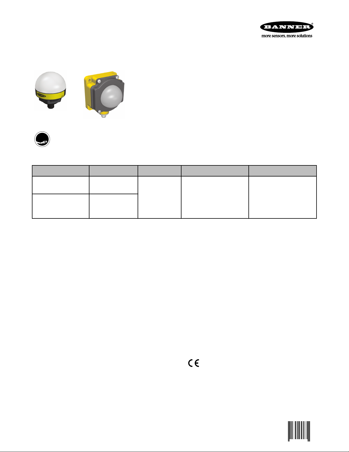
AC-operated, multi-color, general-purpose indicators
For the latest technical information about this product, including specifications, dimensions, and wiring, see www.BannerEngineer-
ing.com.
• Rugged, cost-effective and easy-to-install indicators available in K50 or K80
housing style
• Illumination provides easy-to-see operator guidance and equipment status indication
• Compact devices are completely self-contained — no controller needed
• 85 to 130V ac operation
• Displays 3 colors
• Immune to ambient light, EMI and RFI interference
Call Factory for more information.
Models
Model Construction Connection* LED Function** Inputs
K50LGRYA120Q
K80LGRYA120Q
* Integral QD models are listed.
• For 150 mm PVC pigtail with QD, replace Q with QP in model number (example, K50LGRYA120QP).
• For 2 m (6.5') PVC cable, omit suffix Q from model number (example, K50LGRYA120).
• A model with a QD requires a mating cable (see 5-pin Micro-Style Cordsets with Shield on page 2)
** Contact factory for other colors and color combinations.
50 mm dome/ 30 mm
mount polycarbonate
50 mm dome/Flat or
DIN-mount polycar-
bonate
5-pin Micro QD 3 Color: Green, Red, Yellow 85–130V ac
Specifications
Supply Voltage and Current
85 to 130V ac @ 15 mA max.
Supply Protection Circuitry
Protected against transient voltages
Indicators
LEDs are independently selected: Green, Red, or Yellow.
Input Response Time
Indicator ON/OFF: 1 ms max.
Environmental Rating
Rated IEC IP67. K50L models fully encapsulated; K80L
has encapsulated electronics only. K50L QD models
meet IP69K, per DIN 40050-9; cabled models also
meet IP69K if the cable and cable entrance are proteced from high-pressure spray.
P/N 134548 rev. A 3/17/2011
Connections
5-pin Micro-style integral QD (Q), 150 mm (6") pigtail
QD (QP), or 2 m (6.5') integral cable, depending on
model
K80L models: terminal-wired models available for use
with bulk cable; compression fitting optional. Contact
Factory for cable information.
Operating Conditions
−40° to +50° C (−40° to +122° F)
90% @ 55º C max. relative humidity (non-condensing)
Certifications
Page 2
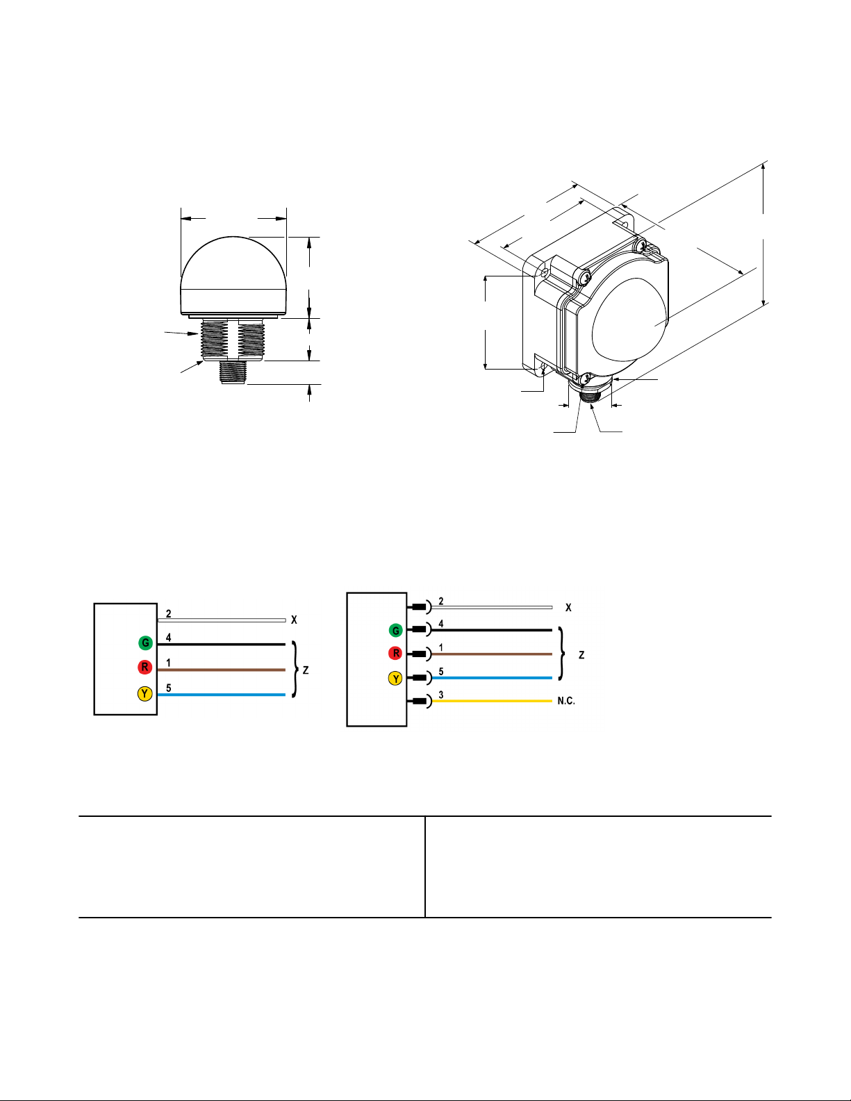
50.0 mm
(1.97")
38 mm (1.50")*
20 mm (0.79")
11 mm (0.43")
M30 x 1.5
(mounting nut
included)
Internal Threads
½ - 14 NPSM
Max. Torque 4.5 Nm
(40 in-lbf)
Max. Torque 2.25 Nm
(20 in-lbf)
109.5 mm
(4.31")
80.8 mm
(3.18")
66.3 mm
(2.61")
26.0 mm
(1.02")
M12 X 1
65.0 mm
(2.56")
65.0 mm
(2.56")
4X 8–32 UNC
Max. Torque 1.12 Nm (10 in–lbf)
4X Ø 5.5 mm (Ø 0.22")
Max. Torque 1.12 Nm (10 in–lbf)
with supplied screws
Internal Threads ½ - 14 NPSM
Max. Torque 2.25 Nm (20 in–lbf)
EZ-LIGHT™ Indicators — 85-130V ac
Dimensions
K50L K80L
Wiring
Cabled Models QD Models Key:
5-pin Micro-Style Cordsets with Shield
5-pin Micro-Style Cordsets with Shield (straight connector)
MQVR3S-506, 2 m (6.5')
MQVR3S-515, 5 m (15')
MQVR3S-530, 9 m (30')
1 = Brown
2 = White
3 =Yellow
4 = Black
5 = Blue
G = Green
R = Red
Y = Yellow
X = V ac Neutral
Z = Input 85 to 130V ac
N.C. = Not Used
5-pin Micro-Style Cordsets with Shield (right-angle connector)
MQVR3S-506RA, 2 m (6.5')
MQVR3S-515RA, 5 m (15')
MQVR3S-530RA, 9 m (30')
2 www.bannerengineering.com - tel: 763-544-3164 P/N 134548 rev. A
Page 3

EZ-LIGHT™ Indicators — 85-130V ac
Mounting Brackets
All measurements in mm
SMB30A
• Right-angle bracket with
curved slot for versatile
orientation
• Clearance for M6 (¼")
hardware
• 30 mm mounting hole
• 12-ga. stainless steel
Hole center spacing: A to B=40.0
Hole size: A=ø 6.3, B=27.3 x 6.3, C=ø 30.5
SMB30FA
• Swivel bracket with tilt and
pan movement for precision adjustment
• 30 mm mounting hole
• 12-ga. 304 stainless steel
A=3/8 - 16 x 50.8
Hole size: B=ø 30.1
SMB30SC
• Swivel bracket with 30 mm
mounting hole
• Black reinforced thermoplastic polyester
• Stainless steel mounting
and swivel locking hardware included
Hole center spacing: A to B=50.8
Hole size: A=ø 7.0
SMBAMS30P
• Flat SMBAMS series
bracket
• 30 mm mounting hole
• Articulation slots for 90+°
rotation
• 12-ga. 300 series stainless
steel
Hole center spacing: A=26.0, A to B=13.0
Hole size: A=26.8 x 7.0, B=ø 6.5, C=ø 31.0
SMB30MM
• 12-ga. stainless steel
bracket with curved
mounting slots for versatility and orientation
• Clearance for M6 (¼")
hardware
• 30 mm mounting hole
Hole center spacing: A=51.0, A to B=25.4
Hole size: A=42.6 x 7.0, B=ø 6.4, C=ø 30.1
SMBAMS30RA
• Right-angle SMBAMS series bracket
• 30 mm mounting hole
• Articulation slots for 90+°
rotation
• 12-ga. cold rolled stainless
steel
Hole center spacing: A=26.0, A to B=13.0
Hole size: A=26.8 x 7.0, B=ø 6.5, C=ø 31.0
P/N 134548 rev. A www.bannerengineering.com - tel: 763-544-3164 3
Page 4

EZ-LIGHT™ Indicators — 85-130V ac
For K80L
SMBDX80D
• DIN-mount bracket for K80L models, mounts on 35 mm DIN
rail
• Hardware included to mount to K80L housing
• Black reinforced thermoplastic
Contact Us
For more information: Contact your local Banner representative or Banner Corporate Offices around the world.
Corporate Headquarters: Banner Engineering Corp. 9714 Tenth Ave. North, Mpls., MN 55441, Tel: 763-544-3164, www.bannerengin-
eering.com, sensors@bannerengineering.com
Europe: Banner Engineering Europe Park Lane, Culliganlaan 2F, Diegem B-1831 BELGIUM,Tel: 32-2 456 07 80, Fax: 32-2 456 07 89,
www.bannereurope.com, mail@bannereurope.com
Latin America: Contact Banner Engineering Corp. (US) or e-mail Mexico: mexico@bannerengineering.com; or Brazil: brasil@banner-
engineering.com
Asia:
Banner Engineering China Shanghai Rep Office Rm. G/H/I, 28th Flr. Cross Region Plaza No. 899, Lingling Road, Shanghai 200030
CHINA, Tel: 86-21-54894500, Fax: 86-21-54894511, www.bannerengineering.com.cn, sensors@bannerengineering.com.cn
Banner Engineering Japan Cent-Urban Building 305 3-23-15, Nishi-Nakajima Yodogawa-Ku, Osaka 532-0011 JAPAN, Tel:
81-6-6309-0411, Fax: 81-6-6309-0416, www.bannerengineering.co.jp, mail@bannerengineering.co.jp
Banner Engineering Asia ─ Taiwan Neihu Technology Park 5F-1, No. 51, Lane 35, Jihu Rd., Taipei 114 TAIWAN, Tel:
886-2-8751-9966, Fax: 886-2-8751-2966, www.bannerengineering.com.tw, info@bannerengineering.com.tw
Banner Engineering India Pune Head Quarters Office, No. 1001 Sai Capital, Opp. ICC Senapati Bapat Road, Pune 411016 INDIA, Tel:
91-20-66405624, Fax: 91-20-66405623, www.bannerengineering.co.in, india@bannerengineering.com
Warranty: Banner Engineering Corporation warrants its products to be free from defects
for a period of one year. Banner Engineering Corporation will repair or replace, free of
charge, any product of its manufacture found to be defective at the time it is returned to
the factory during the warranty period. This warranty does not cover damage or liability
for the improper application of Banner products. This warranty is in lieu of any other
warranty either expressed or implied.
 Loading...