

Page 1

EZ-LIGHT Indicators for 3-Color, 7-Function
121902
Datasheet
DC-operated LED indicators with solid ON or flashing capability and a Euro-style integral QD1. Choose from red, yellow, or
green ON, flashing, or rotating (depending on wiring).
2
Models Construction Inputs
M18GRY2PQ
PNP (Sourcing)
Nickel-plated brass housing, M18x1 thread;
M18GRY2NQ NPN (Sinking)
T30GRY2PQ
thermoplastic diffuser. Fully encapsulated; IP67.
PNP (Sourcing)
Thermoplastic polyester housing, thermoplastic
T30GRY2NQ NPN (Sinking)
K50LGRY2PQ
diffuser. Fully encapsulated; IP67.
PNP (Sourcing)
30 mm threaded polycarbonate base, translucent
K50LGRY2NQ NPN (Sinking)
K50FLGRY2PQ
polycarbonate dome. Fully encapsulated; IP67.
PNP (Sourcing)
Polycarbonate base, translucent polycarbonate
K50FLGRY2NQ NPN (Sinking)
K80LGRY2PQ
3
dome. Fully encapsulated; IP67.
PNP (Sourcing)
ABS and polycarbonate base, translucent
K80LGRY2NQ NPN (Sinking)
polycarbonate dome. Electronics fully encapsulated;
IP67.
Other Models: Standard integral QD models only are listed (mating cordset required). To order 2 m (6.5 ft) cable models,
omit suffix Q from model number (example, M18GRY2P). To order models with 150 mm (6 inch) PVC pigtail with 5-pin
Euro QD connector, replace suffix Q with QP (example, M18GRY2PQP).
Specifications
Supply Voltage and Current
M18 Models: 10 to 30 V dc at 40 mA max.
T30 Models: 10 to 30 V dc at 50 mA max.
K50L, K50FL and K80L Models: 18 to 30 V dc at 50 mA max.
Indicators
Entire translucent diffuser or dome provides indication.
LEDs are independently selected: Green, Red, Yellow, ON steady or
flashing.
For other colors/combinations, contact Factory for availability
Input Response Time
Indicator ON: 250 ms (max.)
Indicator OFF: 10 ms (max.)
Indicator Flash Rate
Single Color: 1 second flash rate (500 ms ON)
Three Color: 1.5 second rotation rate (500 ms per color)
1
Pin 5 is not used; connects to 4-wire QD cordset. If a cordset other than those specified in this document is used, use a 5-pin mating cordset.
2
Contact Factory for other colors/color combinations, including: blue, white, orange.
3
K80L Models: Standard 5-pin Euro integral QD connector models only are listed (mating cordset required). For terminal-wired
model, omit suffix Q (example, K80LGRY2P).
Original Document
121902 Rev. I
Connections
K80L Models: 5-pin Euro-style integral QD (Q) standard. Terminalwired models available for use with bulk cable; compression fitting
optional. Contact Factory for cable information.
Other Models: 5-pin Euro-style integral QD (Q); 6" pigtail QD (QP), (do
not use center pin 5); or 5-wire, 2 m (6.5') integral cable
Operating Conditions
Temperature: –40 °C to 50 °C (–40 °F to 122 °F)
Environmental Rating
IEC IP67
K80L has encapsulated electronics only; other models fully
encapsulated
20 February 2014
Page 2
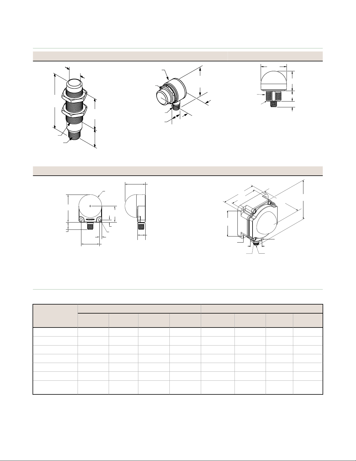
30 mm
(1.2")
23 mm
(0.9")
Ø16.5 mm
(0.65")
61 mm
(2.4")
M12 X 1
M18 X 1
M30 x 1.5
Thread
Ø 40.0 mm
(1.57")
45.0 mm
(1.77")
63.7 mm
(2.51")
Ø 15 mm
(0.59")
M12 X 1
50.0 mm
(1.97")
38 mm (1.50")*
20 mm (0.79")
11 mm (0.43")
M30 x 1.5
(mounting nut
included)
Internal Threads
½ - 14 NPSM
Max. Torque 4.5 Nm
(40 in-lbf)
Max. Torque 2.25 Nm
(20 in-lbf)
60.0
[2.36"]
35.0
[1.38"]
16.0 [0.63"]
40.0 [1.58"]
2x 5.0 [0.20"]
2x 5.0 [0.20"]
2x 5.5 [0.21"]
Ø50 [1.97"]
17.0 [0.67"]
44.6 [1.76"]
109.5 mm
(4.31")
80.8 mm
(3.18")
66.3 mm
(2.61")
26.0 mm
(1.02")
M12 X 1
65.0 mm
(2.56")
65.0 mm
(2.56")
4X 8–32 UNC
Max. Torque 1.12 Nm (10 in–lbf)
4X Ø 5.5 mm (Ø 0.22")
Max. Torque 1.12 Nm (10 in–lbf)
with supplied screws
Internal Threads ½ - 14 NPSM
Max. Torque 2.25 Nm (20 in–lbf)
EZ-LIGHT Indicators for 3-Color, 7-Function
Dimensions
M18 Models T30 Models K50L Models
K50FL Models K80L Models
Wiring
Table 1: Select from 7 operating schemes, depending on wiring
PNP Models NPN Models
LED Function
Red ON +V dc 0 V dc 0 V dc +V dc
Red Flashing +V dc +V dc 0 V dc 0 V dc 0 V dc +V dc
Yellow ON +V dc 0 V dc 0 V dc +V dc
Yellow Flashing +V dc +V dc 0 V dc 0 V dc 0 V dc +V dc
Green ON +V dc 0 V dc 0 V dc +V dc
Green Flashing +V dc +V dc 0 V dc 0 V dc 0 V dc +V dc
Rotating
Red-Green-Yellow
2 www.bannerengineering.com - tel: 763-544-3164 P/N 121902 Rev. I
Brown
Wire
White
Wire
Black Wire Blue Wire Blue Wire White Wire
Black
Wire
Brown
+V dc +V dc +V dc 0 V dc 0 V dc 0 V dc 0 V dc +V dc
Wire
Page 3

2
3
4
1
44 Typ.
ø 14.5
M12 x 1
2
3
4
1
32 Typ.
[1.26"]
30 Typ.
[1.18"]
ø 14.5 [0.57"]
M12 x 1
30
41
46
A
B
C
EZ-LIGHT Indicators for 3-Color, 7-Function
Table 2: Only QD wiring is shown; cabled wiring is functionally identical.
PNP Models NPN Models Pinout
Accessories
4-Pin Threaded M12/Euro-Style Cordsets
Model Length Style Dimensions Pinout
MQDC-406 1.83 m (6 ft)
MQDC-415 4.57 m (15 ft)
MQDC-430 9.14 m (30 ft)
MQDC-450 15.2 m (50 ft)
MQDC-406RA 1.83 m (6 ft)
MQDC-415RA 4.57 m (15 ft)
MQDC-430RA 9.14 m (30 ft)
MQDC-450RA 15.2 m (50 ft)
G = Green
R = Red
Y = Yellow
X = Not Used
Straight
Right-Angle
1 = Brown
2 = White
3 = Blue
4 = Black
5 = Gray
Z = Input Connections (see table
above
1 = Brown
2 = White
3 = Blue
4 = Black
To order bulk cable for terminal-wired K80L models, contact the factory. If cables other than those listed are used, use a
5-pin mating cable.
Brackets
For use with M18 and T18 models or
SMB18A
• Right-angle mounting bracket
with a curved slot for versatile
orientation
• 12-ga. stainless steel
• 18 mm sensor mounting hole
• Clearance for M4 (#8) hardware
Hole center spacing: A to B = 24.2
Hole size: A = ø 4.6, B = 17.0 × 4.6, C = ø 18.5
base-mount T30 models. Other available
18 mm dia. brackets:
SMB1815SF
SMB18Q
SMB18SF
SMB312PD
SMBAMS18RA
SMBAMS18P
P/N 121902 Rev. I www.bannerengineering.com - tel: 763-544-3164 3
Page 4

45
61
69
A
B
C
89
89
SMB30A
• Right-angle bracket with curved slot
• Clearance for M6 (¼ in) hardware
• Mounting hole for 30 mm sensor
• 12-ga. stainless steel
Hole center spacing: A to B=40
Hole size: A=ø 6.3, B= 27.1 x 6.3, C=ø 30.5
SMBDX80DIN
Black reinforced thermoplastic
Bracket for mounting on a 35 mm DIN
rail
EZ-LIGHT Indicators for 3-Color, 7-Function
for versatile orientation
Brackets
For use with T30 models or base-mount
K50L models. Other available 30 mm
diameter brackets are:
SMBAMS30RA
SMBAMS30P
SMB30SC
SMB30SC
SMB30MM
SMB3018SC
K50FL models include a 48 mm (1.9 inch)
circular velcro mounting kit for easy
mounting with no additional hardware
Banner Engineering Corp Limited Warranty
Banner Engineering Corp. warrants its products to be free from defects in material and workmanship for one year following
the date of shipment. Banner Engineering Corp. will repair or replace, free of charge, any product of its manufacture
which, at the time it is returned to the factory, is found to have been defective during the warranty period. This warranty
does not cover damage or liability for misuse, abuse, or the improper application or installation of the Banner product.
THIS LIMITED WARRANTY IS EXCLUSIVE AND IN LIEU OF ALL OTHER WARRANTIES WHETHER EXPRESS OR
IMPLIED (INCLUDING, WITHOUT LIMITATION, ANY WARRANTY OF MERCHANTABILITY OR FITNESS FOR A
PARTICULAR PURPOSE), AND WHETHER ARISING UNDER COURSE OF PERFORMANCE, COURSE OF DEALING OR
TRADE USAGE.
This Warranty is exclusive and limited to repair or, at the discretion of Banner Engineering Corp., replacement. IN NO
EVENT SHALL BANNER ENGINEERING CORP. BE LIABLE TO BUYER OR ANY OTHER PERSON OR ENTITY FOR
ANY EXTRA COSTS, EXPENSES, LOSSES, LOSS OF PROFITS, OR ANY INCIDENTAL, CONSEQUENTIAL OR
SPECIAL DAMAGES RESULTING FROM ANY PRODUCT DEFECT OR FROM THE USE OR INABILITY TO USE THE
PRODUCT, WHETHER ARISING IN CONTRACT OR WARRANTY, STATUTE, TORT, STRICT LIABILITY,
NEGLIGENCE, OR OTHERWISE.
Banner Engineering Corp. reserves the right to change, modify or improve the design of the product without assuming any
obligations or liabilities relating to any product previously manufactured by Banner Engineering Corp.
www.bannerengineering.com - tel: 763-544-3164
 Loading...