

Page 1
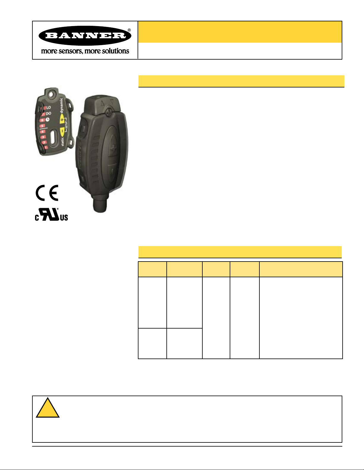
FI22FP Series
!
Low-Profile, Inline Plastic Fiber Optic Sensor
Features
• Low-profile fiber optic sensors are designed for inconspicuous surface mounting
• 8-segment LED light bar indicates relative received signal strength, sensing contrast,
programming status, and diagnostic warnings
• Easy-to-set automatic Expert-style TEACH options including static, dynamic, and
single-point programming plus manual adjustment for fine-tuning
• Smart power-control algorithms to maximize sensing contrast
• Fast 500-microsecond sensing response
• Programmable 30-millisecond pulse stretcher (OFF delay)
• Extreme programming flexibility via two push buttons or a remote input wire
• Output may be programmed for either light or dark operate
• Bipolar discrete outputs: one current sourcing (PNP) and one current sinking (NPN)
• Visible red (660 nm) light source
• Easy-to-read TEACH and signal strength readout, plus indicators for a continuous
readout of operating status
Models
Model Cable*
2 m (6.5')
FI22FP
FI22FP
* 9 m (30’) cables are available by adding suffix “W/30” to the model number of any cabled sensor
(e.g., FI22FP W/30). A model with a QD connector requires a mating cable (see page 9).
**See page 2 for beam patterns and excess gain curves.
5-wire
integral cable
Integral 6-pin
Q
Pico-style QD
Supply
Voltage
10V dc to
30V dc
Output
Type
Bipolar
NPN/PNP
Maximum Range**
Range varies depending on sensing
mode and fiber optic(s) used; see
below and page 2 for typical values.
Opposed Mode
PIT26U Fiber: 60 mm (2.36")
PIT46U Fiber: 260 mm (10.24")
PIT66U Fiber: 540 mm (21.26")
Diffuse Mode
PBT26U Fiber: 15 mm (0.59")
PBT46U Fiber: 65 mm (2.56")
PBT66U Fiber: 115 mm (4.53")
WARNING . . . Not To Be Used for Personnel Protection
Never use this product as a sensing device for personnel protection. Doing so could lead to serious injury or death.
This product does NOT include the self-checking redundant circuitry necessary to allow its use in personnel safety
applications. A sensor failure or malfunction can cause either an energized or de-energized sensor output condition. Consult your
cur
rent Banner Safety Products catalog for safety products which meet OSHA, ANSI and IEC standards for personnel protection.
Printed in USA 01/12 P/N 108899 rev. C
Page 2
FI22FP Low-Profile Inline Plastic Fiber Optic Sensor
1
10
100
10 mm
.4 in
100 mm
4 in
1000 mm
40 in
1 mm
.04 in
1000
E
X
C
E
S
S
G
A
I
N
DISTANCE
1
10
100
10 mm
.4 in
100 mm
4 in
1000 mm
40 in
1 mm
.04 in
1000
E
X
C
E
S
S
G
A
I
N
DISTANCE
1
10
100
10 mm
.4 in
100 mm
4 in
1000 mm
40 in
1 mm
.04 in
1000
E
X
C
E
S
S
G
A
I
N
DISTANCE
FI22FP
PIT26U
PIT46U
PIT66U
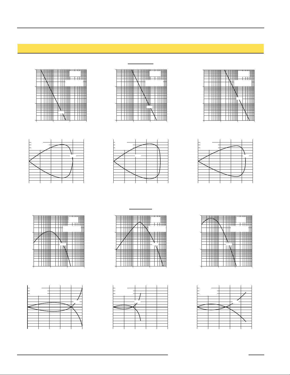
Opposed Mode
with PIT26U Fiber
FI22FP
Opposed Mode
with PIT46U Fiber
FI22FP
Opposed Mode
with PIT66U Fiber
1
10
100
10 mm
.4 in
100 mm
4 in
1000 mm
40 in
1 mm
.04 in
1000
E
X
C
E
S
S
G
A
I
N
DISTANCE
1
10
100
10 mm
.4 in
100 mm
4 in
1000 mm
40 in
1 mm
.04 in
1000
E
X
C
E
S
S
G
A
I
N
DISTANCE
PIT46U
PIT66U
FI22FP
Opposed Mode
with PIT46U Fiber
FI22FP
Opposed Mode
with PIT66U Fiber
1
10
100
10 mm
.4 in
100 mm
4 in
1000 mm
40 in
1 mm
.04 in
1000
E
X
C
E
S
S
G
A
I
N
DISTANCE
PIT66U
FI22FP
Opposed Mode
with PIT66U Fiber
625 mm
25.0 in
500 mm
20.0 in
375 mm
15.0 in
250 mm
10.0 in
125 mm
5.0 in
0
0
50 mm
100 mm
150 mm
50 mm
100 mm
150 mm
0
2.0 in
4.0 in
6.0 in
2.0 in
4.0 in
6.0 in
0.80 in
1.60 in
2.40 in
0.80 in
1.60 in
2.40 in
0.20 in
0.40 in
0.60 in
0.20 in
0.40 in
0.60 in
DISTANCE
FI22FP
Opposed Mode
with PIT66U Fiber
300 mm
12.0 in
240 mm
9.6 in
180 mm
7.2 in
120 mm
4.8 in
60 mm
2.4 in
0
0
20 mm
40 mm
60 mm
20 mm
40 mm
60 mm
0
DISTANCE
FI22FP
Opposed Mode
with PIT46U Fiber
75 mm
3.00 in
60 mm
2.40 in
45 mm
1.80 in
30 mm
1.20 in
15 mm
0.60 in
0
0
5 mm
10 mm
15 mm
5 mm
10 mm
15 mm
0
DISTANCE
FI22FP
Opposed Mode
with PIT26U Fiber
PIT26U
PIT46U
PIT66U
625 mm
25.0 in
500 mm
20.0 in
375 mm
15.0 in
250 mm
10.0 in
125 mm
5.0 in
0
0
50 mm
100 mm
150 mm
50 mm
100 mm
150 mm
0
2.0 in
4.0 in
6.0 in
2.0 in
4.0 in
6.0 in
0.80 in
1.60 in
2.40 in
0.80 in
1.60 in
2.40 in
DISTANCE
FI22FP
Opposed Mode
with PIT66U Fiber
300 mm
12.0 in
240 mm
9.6 in
180 mm
7.2 in
120 mm
4.8 in
60 mm
2.4 in
0
0
20 mm
40 mm
60 mm
20 mm
40 mm
60 mm
0
DISTANCE
FI22FP
Opposed Mode
with PIT46U Fiber
PIT46U
PIT66U
625 mm
25.0 in
500 mm
20.0 in
375 mm
15.0 in
250 mm
10.0 in
125 mm
5.0 in
0
0
50 mm
100 mm
150 mm
50 mm
100 mm
150 mm
0
2.0 in
4.0 in
6.0 in
2.0 in
4.0 in
6.0 in
DISTANCE
FI22FP
Opposed Mode
with PIT66U Fiber
PIT66U
1
10
100
1 mm
.04 in
10 mm
0.4 in
100 mm
4 in
0.1 mm
.004 in
1000
E
X
C
E
S
S
G
A
I
N
DISTANCE
1
10
100
1 mm
.04 in
10 mm
0.4 in
100 mm
4 in
0.1 mm
.004 in
1000
E
X
C
E
S
S
G
A
I
N
DISTANCE
1
10
100
10 mm
.4 in
100 mm
4 in
1000 mm
40 in
1 mm
.04 in
1000
E
X
C
E
S
S
G
A
I
N
DISTANCE
FI22
Diffuse Mode
with PBT26U Fiber
FI22 FI22
Diffuse Mode
with PBT66U Fiber
PBT66UPBT26U
Diffuse Mode
with PBT46U Fiber
PBT46U
1
10
100
1 mm
.04 in
10 mm
0.4 in
100 mm
4 in
0.1 mm
.004 in
1000
E
X
C
E
S
S
G
A
I
N
DISTANCE
1
10
100
10 mm
.4 in
100 mm
4 in
1000 mm
40 in
1 mm
.04 in
1000
E
X
C
E
S
S
G
A
I
N
DISTANCE
FI22 FI22
Diffuse Mode
with PBT66U Fiber
PBT66UPBT26U
Diffuse Mode
with PBT46U Fiber
PBT46U
1
10
100
10 mm
.4 in
100 mm
4 in
1000 mm
40 in
1 mm
.04 in
1000
E
X
C
E
S
S
G
A
I
N
DISTANCE
Diffuse Mode
with PBT66U Fiber
PBT66UPBT26U
125 mm
5.0 in
100 mm
4.0 in
75 mm
3.0 in
50 mm
2.0 in
25 mm
1.0 in
0
0
20 mm
40 mm
60 mm
20 mm
40 mm
60 mm
0
0.80 in
1.60 in
2.40 in
0.80 in
1.60 in
2.40 in
0.80 in
1.60 in
2.40 in
0.80 in
1.60 in
2.40 in
0.08 in
0.16 in
0.24 in
0.08 in
0.16 in
0.24 in
DISTANCE
FI22FP
Diffuse Mode
with PBT66U Fiber
125 mm
5.0 in
100 mm
4.0 in
75 mm
3.0 in
50 mm
2.0 in
25 mm
1.0 in
0
0
20 mm
40 mm
60 mm
20 mm
40 mm
60 mm
0
DISTANCE
FI22FP
Diffuse Mode
with PBT46U Fiber
15 mm
0.56 in
12 mm
0.48 in
9 mm
0.36 in
6 mm
0.24 in
3 mm
0.12 in
0
0
2 mm
4 mm
6 mm
2 mm
4 mm
6 mm
0
DISTANCE
FI22FP
Diffuse Mode
with PBT26U Fiber
PBT66U
PBT26U
PBT46U
125 mm
5.0 in
100 mm
4.0 in
75 mm
3.0 in
50 mm
2.0 in
25 mm
1.0 in
0
0
20 mm
40 mm
60 mm
20 mm
40 mm
60 mm
0
0.80 in
1.60 in
2.40 in
0.80 in
1.60 in
2.40 in
0.80 in
1.60 in
2.40 in
0.80 in
1.60 in
2.40 in
DISTANCE
FI22FP
Diffuse Mode
with PBT66U Fiber
125 mm
5.0 in
100 mm
4.0 in
75 mm
3.0 in
50 mm
2.0 in
25 mm
1.0 in
0
0
20 mm
40 mm
60 mm
20 mm
40 mm
60 mm
0
DISTANCE
FI22FP
Diffuse Mode
with PBT46U Fiber
PBT66U
PBT46U
125 mm
5.0 in
100 mm
4.0 in
75 mm
3.0 in
50 mm
2.0 in
25 mm
1.0 in
0
0
20 mm
40 mm
60 mm
20 mm
40 mm
60 mm
0
0.80 in
1.60 in
2.40 in
0.80 in
1.60 in
2.40 in
DISTANCE
FI22FP
Diffuse Mode
with PBT66U Fiber
PBT66U
FI22FP Low-Profile Inline Plastic Fiber Optic Sensor
Excess Gain Curves and Beam Patterns
Opposed Mode
Diffuse Mode
2 P/N 108899 rev. C
Banner Engineering Corp. • Minneapolis, MN U.S.A.
www.bannerengineering.com • Tel: 763. 544.3164
Page 3
FI22FP Low-Profile Inline Plastic Fiber Optic Sensor
FI22FP Low-Profile Inline Plastic Fiber Optic Sensor
Programming
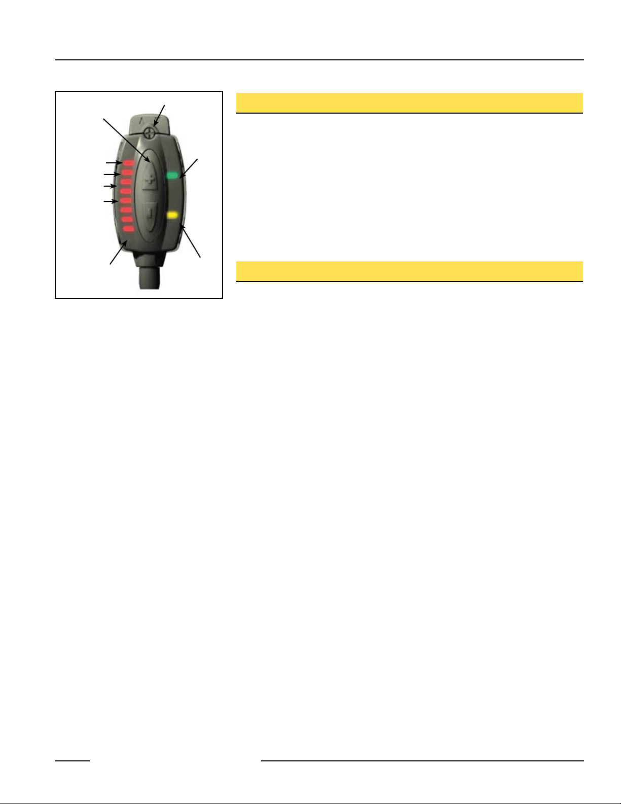
Push Buttons
SETUP
Status
Indicators:
Light
Dark Operate
Delay
Switching
Point
Bargraph
Display
Figure 1. FI22FP features
Fiber Ports
Yellow Output
Conducting
Indicator
Green
Power ON
Indicator
Overview
The FI22FP is an easy-to-use, low-profile fiber optic sensor. It provides high-performance
sensing in low-contrast applications and its small size lets it mount almost anywhere.
Configuration options include SETUP mode plus static, dynamic and single-point TEACHmode programming, in addition to manual fine adjustment, remote programming and
security lockout options.
The sensor has bipolar outputs, one each NPN and PNP.
The sensor’s compact housing has a large, easy-to-see bargraph display plus bright LEDs
for easy programming and status monitoring during operation. The sensor quickly snapmounts to its custom bracket (included with sensor).
Sensor Programming
Sensor configuration is accomplished through TEACH-mode programming and SETUP
mode. After TEACH mode has defined the sensing parameters, SETUP mode may be used
to enable the delay or to change the light/dark operate status. Manual Adjust may be used
to fine-tune the thresholds (see page 9). Two push buttons, Dynamic (+) and Static (-), or
the remote wire, may be used to access and set programming parameters.
Sensor programming may be accomplished using any of three TEACH methods. A single
switching threshold may be programmed using either dynamic (on-the-fly) or static TEACH.
In addition, single-point static TEACH may be used to define a sensing window, centered on
a single taught condition. Single-point TEACH can be accomplished only statically.
Remote Programming
The Remote Programming function may be used to program the sensor remotely or to
disable the push buttons for security. Connect the gray wire of the sensor to ground (0V
dc), with a remote programming switch connected between them. Pulse the remote line
according to the diagrams in the programming procedures. The length of the individual
gramming pulses is equal to the value T:
ro
p
0.04 seconds ≤ T ≤ 0.8 seconds
Returning to RUN Mode
TEACH and SETUP modes each may be exited either after the 60-second time-out, or by
exiting the process:
static TEACH mode, press and hold the Static (-) button (or hold the remote line) for 2
• In
seconds. The sensor returns to RUN mode without saving any new settings.
• In
SETUP mode, press and hold both the Static (-) and Dynamic (+) buttons (or hold
the remote line) for 2 seconds. The sensor returns to RUN mode and saves the current
setting.
Banner Engineering Corp. • Minneapolis, MN U.S.A.
P/N 108899 rev. C 3
www.bannerengineering.com • Tel: 763. 544.3164
Page 4
FI22FP Low-Profile Inline Plastic Fiber Optic Sensor
Sensor positions
threshold midway
between taught conditions
Darkest
(no signal)
Most Light
(saturated
signal)
Output OFF Output ON
2nd Taught
Condition
1st Taught
Condition
Position
adjusted by
Manual Adjust
T
T T
T
T
T T
T
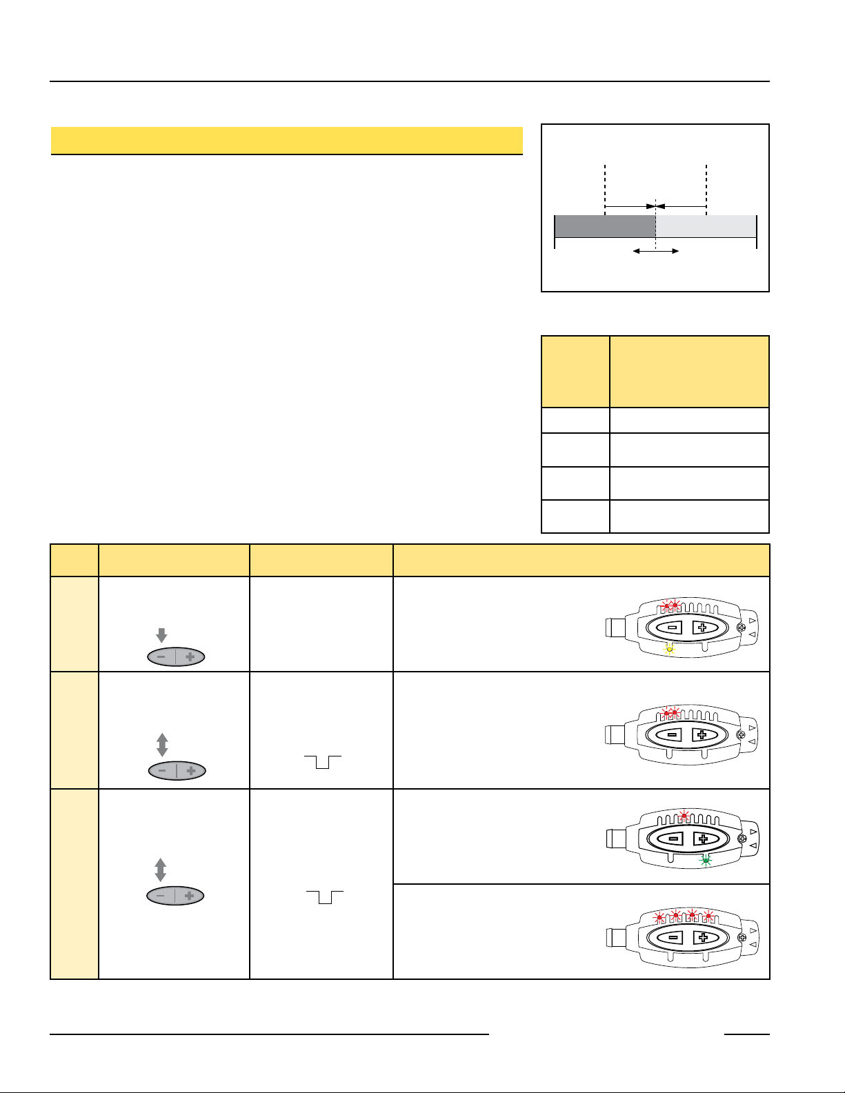
Two-Point Static TEACH (Switch Point)
• Sets a single switching threshold
• Threshold position is adjustable using “+” and “-” buttons (Manual Adjust)
Two-Point TEACH is the traditional setup method, used when two conditions can be
presented by the user. The sensor locates a single sensing threshold (the switch point)
midway between the two taught conditions, with the Output ON condition on one side, and
the Output OFF condition on the other (see Figure 2).
The first condition taught is the ON condition. The Output ON and OFF conditions can be
reversed by changing Light/Dark Operate status in SETUP mode.
Two-Point TEACH and Manual Adjust
Using Manual Adjust with Two-Point TEACH moves the switching threshold. The lighted
LED on the bargraph will move to exhibit the relative amount of received signal.
Figure 2. Two-Point TEACH (Light Operate
Bargraph
LED
Following
TEACH
6 to 8 Excellent: Very stable operation
4 to 5
2 to 3
1
shown)
Relative Signal Difference/
Recommendation
Good: Minor sensing variables
will not affect sensing reliability.
Low: Minor sensing variables
may affect sensing reliability.
Unreliable: Consider an
alternate sensing scheme.
Access
Learn Output
Learn Output
Push Button
0.04 sec. ≤ “click” ≤ 0.8 sec.
• Press and Hold
> 2 seconds
TEACH Mode
• Present Output ON
condition
• Click push button
ON Condition
• Present Output OFF
condition
• Click push button
OFF Condition
Remote Line
0.04 sec. ≤ T ≤ 0.8 sec.
No action required;
sensor is ready for 1st
TEACH condition.
• Present
Output ON
condition
• Single-pulse remote line
• Present
Output OFF
condition
• Single-pulse remote line
Result
Power LED: OFF
Output LED: ON
Status LEDs: #2 & 3 Alternately flashing
Power LED: OFF
Output LED: OFF
Status LEDs: #2 & 3 Alternately flashing
Teach Accepted
Power LED: ON
Bargraph: One LED
relative contrast (good
flashes to show
signal
difference shown; see table above)
Sensor returns to Run mode
Teach Unacceptable
Power LED: OFF
Bargraph: #1, 3, 5,
7 Alternately flash
to show failure
Sensor returns to “Learn Output ON”
condition
4 P/N 108899 rev. C
Banner Engineering Corp. • Minneapolis, MN U.S.A.
www.bannerengineering.com • Tel: 763. 544.3164
Page 5

Sensor positions
threshold midway
between taught conditions
Sensor positions
threshold midway
between taught conditions
Darkest
(no signal)
Most Light
(saturated
signal)
Output OFF
Output ON
Darkest Taught
Condition
Lightest Taught
Condition
Position
adjusted by
Manual Adjust
Darkest
(no signal)
Most Light
(saturated
signal)
Output OFF Output ON
2nd Taught
Condition
1st Taught
Condition
Position
adjusted by
Manual Adjust
Figure 3. Two-Point Dynamic TEACH
T T T T
T
T T
T T T
T T
T T
T
T T T T
T
T T
T T T
T T
T T
T
T T T T
T
T T
T T T
T T
T T
T
(Light Operate shown)
Bargraph
LED
Following
Relative Signal Difference/
Recommendation
TEACH
6 to 8 Excellent: Very stable operation.
4 to 5
2 to 3
1
Good: Minor sensing variables
will not affect sensing reliability.
Low: Minor sensing variables
may affect sensing reliability.
Unreliable: Consider an
alternate sensing scheme.
FI22FP Low-Profile Inline Plastic Fiber Optic Sensor
Dynamic TEACH and Adaptive Thresholds
• Teach on-the-fly
• Sets a single switching threshold
reshold position is adjustable using “+” and “-” buttons (Manual Adjust)
• Th
Dynamic TEACH is best used when a machine or process may not be stopped for
teaching. A variation of two-point TEACH, it programs the sensor during actual machine
run conditions, taking multiple samples of the light and dark conditions and automatically
setting the threshold at the optimum level (see Figure 3).
amic TEACH activates the sensor’s adaptive threshold system, which continuously
yn
D
tracks minimum and maximum signal levels, and automatically maintains centering of the
switch point between the light and dark conditions. The adaptive threshold system remains
in effect during RUN mode. The adaptive routine saves to non-volatile memory at least once
per hour.
n Dynamic TEACH mode is used, the output ON state (light or dark operate) will remain
he
W
as it was last programmed. To change the output ON state, use SETUP mode (see page 7).
The
sensing set point may be adjusted (fine-tuned) whenever the sensor is in RUN mode by
clicking the “+” and “-” buttons. However, when a manual adjustment is made, the adaptive
thr
eshold system is disabled (cancelled).
Access
TEACH Mode
Learn Output
ON Condition
Learn Output
OFF Condition
P/N 108899 rev. C 5
Push Button Remote Line Result
• Press and Hold
> 2 seconds
• Hold remote line
(to ground)
low
> 2 seconds
• Continue to hold
• Present Output ON and
OFF conditions
• Present Output ON
OFF conditions
• Continue to hold
line low (to ground)
• Release • Release remote line/
switch
Banner Engineering Corp. • Minneapolis, MN U.S.A.
www.bannerengineering.com • Tel: 763. 544.3164
and
remote
Power LED: OFF
Bargraph: #6 & 7 Alternately flashing
Power LED: OFF
Bargraph: #6 & 7 Alternately flashing
Teach Accepted
Power LED: ON
Bargraph: One LED
flashes to show
relative contrast (good signal
difference shown; see table above)
Sensor returns to Run mode with new settings
Teach Unacceptable
Power LED: OFF
Bargraph: #1, 3, 5,
7 Alternately flash
to show failure
Sensor returns to Run mode
without changing settings
Page 6

FI22FP Low-Profile Inline Plastic Fiber Optic Sensor
Sensor positions
threshold midway
between taught conditions
Sensor positions
threshold midway
between taught conditions
Darkest
(no signal)
Darkest
(no signal)
Most Light
(saturated
signal)
Most Light
(saturated
signal)
Single
taught
point
Sensing window size
adjusted by
Manual Adjust
Output OFF Output OFF
Output OFF
Output ON
Output ON
Darkest Taught
Condition
Lightest Taught
Condition
Position
adjusted by
Manual Adjust
Darkest
(no signal)
Most Light
(saturated
signal)
Output OFF Output ON
2nd Taught
Condition
1st Taught
Condition
Position
adjusted by
Manual Adjust
T
T T
T
T T
T
Single-Point Static TEACH (Sensing Window)
• Sets a single ON condition
• All other conditions (lighter or darker) result in OFF output
• Sensing window size (sensitivity) is adjustable using “+” and “-” buttons
(Manual Adjust)
Single-Point TEACH is most useful when a product may not always appear in the same
place, or when other signals may appear. Single-point TEACH programs a sensing window,
with the Output ON condition inside the window, and the Output OFF conditions outside the
window (see Figure 4). Output ON and OFF conditions can be reversed by changing Light/
Dark Operate status in SETUP mode.
Single-Point TEACH programming may be accomplished only using Static TEACH. The
sensor learns a single sensing condition, and adds switching thresholds above and below
the taught condition to create a sensing window.
Single-Point TEACH and Manual Adjust
Using Manual Adjust with Single-Point TEACH expands or contracts the size of the window.
The lighted LEDs on the light bar separate to a greater or lesser extent to exhibit the relative
sensing window size.
Figure 4. Single-Point TEACH (Light
Operate shown)
Access
TEACH Mode
Learn Set Point
(Output ON) Condition
Push Button
0.04 sec. ≤ “click” ≤ 0.8 sec.
• Press and Hold
> 2 seconds
• Present Output ON
conditions
• Double-click push button
Remote Line
0.04 sec. ≤ T ≤ 0.8 sec.
• Present Output ON
condition
• Single-pulse
• Double-pulse
remote line
remote line
Result
Power LED: OFF
Output LED: ON (Push Button)
Output LED: OFF (Remote)
Static LEDs: #2 & 3 alternately flashing
Teach Accepted
Power LED: ON
Bargraph: 2 indicators flash together to
show single-point Teach accepted
Sensor returns to Run mode with
new settings
Teach Unacceptable
Power LED: OFF
Bargraph: #1, 3, 5, 7 flash to show failure
Sensor returns to “Teach 1st Condition”
6 P/N 108899 rev. C
Banner Engineering Corp. • Minneapolis, MN U.S.A.
www.bannerengineering.com • Tel: 763. 544.3164
Page 7

FI22FP Low-Profile Inline Plastic Fiber Optic Sensor
T T
T T T
T T
T T
T
SETUP Mode
SETUP mode is used to change sensor output response for:
SETUP
Status
Indicators
Figure 5. SETUP mode
{
Press and
hold
both push
buttons > 2
seconds
to access
SETUP mode
• Light or Dark operate
• 30-millisecond pulse stretcher (OFF delay), if required.
The status LEDs, active only during SETUP mode, indicate the output response
figuration when the sensor will be in RUN mode. Four combinations are possible:
con
Light Operate, No Delay
Da
rk Operate, No Delay
Dark Operate, 30 ms Delay
Light Operate, 30 ms Delay
To access SETUP mode and change the output response settings:
1. Press and hold BOTH push buttons (or double-pulse Remote line) until the green LED
indicator turns OFF.
lick EITHER push button (or pulse Remote line) to toggle through the four possible
2. C
setting combinations.
3. P
ress and hold both push buttons (or hold Remote line) until the green LED indicator
turns ON, indicating return to RUN mode.
NOTES: • If SETUP mode programming is interrupted and remains inactive for 60
seconds, the sensor returns to RUN mode with the most recent settings
(i.e., exits and saves current selection).
•
SETUP mode operates in the “background”, while the outputs are active.
Manual Adjust
Use during Run mode, accomplished via push buttons only.
Two-Point TEACH (Static or Dynamic):
• Fine-tunes sensing sensitivity
• Press “+” to increase; press “-” to decrease
Single-Point TEACH:
• Adjusts sensing window size (tolerance) for the single-point target condition
• Press “+” to increase; press “-” to decrease
The lighted bargraph LEDs move to reflect the increase or decrease.
Push Button Disable
In addition to its programming function, Remote Programming may be used to disable the
push buttons for security. Disabling the push buttons prevents undesired tampering with
the programming settings. Connect the gray wire of the sensor as described on page 9, and
ou
r-pulse to either enable or disable the push buttons:
f
P/N 108899 rev. C 7
Banner Engineering Corp. • Minneapolis, MN U.S.A.
www.bannerengineering.com • Tel: 763. 544.3164
Page 8

FI22FP Low-Profile Inline Plastic Fiber Optic Sensor
Specifications
Sensing Beam
Supply Voltage
Supply Protection Circuitry
Delay at Power Up
Output Configuration
Output Rating
Output Protection
Output Response Time
Repeatability
Adjustments
Indicators
Construction
Environmental Rating
Connections
Operating Conditions
660 nm visible red
10 to 30V dc (10% max. ripple) @ less than 32 mA exclusive of load
Protected against reverse polarity, over voltage, and transient voltages
250 milliseconds max.; outputs do not conduct during this time
Bipolar: 1 current sourcing (PNP) and 1 current sinking (NPN)
100 mA maximum load @25° C (derate 1 mA per °C increase)
OFF-state leakage current: < 50 µA at 30V dc
ON-state saturation voltage:
NPN: < 200 mV @ 10 mA and 1V @ 100 mA load
PNP: < 1.5V @ 10 mA and 2.0V @ 100 mA load
Protected against output short-circuit, continuous overload, transient over-voltages, and false pulse
on power up
500 microseconds
100 microseconds
2 push buttons and remote wire
• Expert Teach programming (two-point static, dynamic, and single-point static)
• Manually adjust (+/–) thresholds (from buttons only)
• LO/DO and Off Delay configurable (from buttons or remote wire)
• Push-button lockout (from remote wire only)
8-segment red bargraph:
Light-to-dark signal difference relative to taught condition (single-point TEACH), or
Sensing contrast (two-point
Green LED: Power On
ellow LED: Output conducting
Y
PC/ABS blend plastic housing; polycarbonate cover
IP67, NEMA 6
5-conductor 2 m (6.5') PVC cable, 9 m (30') PVC cable, or 6-pin integral Pico-style quick-disconnect
Temperature: -10° to +55°C
Relative Humidity: 90% @ 50° C (non-condensing)
TEACH)
Certifications
Banner Engineering Corp. • Minneapolis, MN U.S.A.
8 P/N 108899 rev. C
www.bannerengineering.com • Tel: 763. 544.3164
Page 9

50.0 mm
(1.98")
Pico-style
Quick Disconnect
Integral
Cable
23.0 mm
(0.91")
14.5 mm
(0.57")
7.0 mm
(0.28")
25.0 mm
(0.98")
6.0 mm
(0.24")
12.1 mm
(0.48")
10.5 mm
(0.41")
Sensor
FI22FP Low-Profile Inline Plastic Fiber Optic Sensor
Sensor and Bracket Dimensions
Bracket
Figure 6. Installing plastic optical fiber into
the FI22FP fiber ports
Installing the Optical Fibers
To install fibers:
1. Use a small Phillips screwdriver to loosen set screw, as shown in Figure 6.
2. Insert prepared fiber ends (2.2 mm diameter) into emitter and receiver ports, as far as
they will go.
3. H
olding fibers in place, tighten screw to lock in securely.
Banner Engineering Corp. • Minneapolis, MN U.S.A.
P/N 108899 rev. C 9
www.bannerengineering.com • Tel: 763. 544.3164
Page 10

FI22FP Low-Profile Inline Plastic Fiber Optic Sensor
bn
Remote
Teach
bu
wh
bk
gy
+
10 - 30V dc
–
Load
Load
100 mA max. load
bn
Remote
Teach
bu
wh
bk
gy
+
10 - 30V dc
–
Load
Load
100 mA max. load
28 mm max.
(1.1")
ø 10 mm max.
(0.4")
20 mm
(0.8")
25 mm max.
(1.0")
ø12 mm max.
(0.5")
Brown Wire
Gray Wire
Pink Wire
Blue Wire
Black Wire
White Wire
FI22FP Low-Profile Inline Plastic Fiber Optic Sensor
Hookups
Cabled Models Quick-Disconnect Models
NOTE: Pink wire not used
Accessories
Quick-Disconnect Cables
Style Model Length Dimensions Pinout
6-pin
Pico-style
straight
6-pin
Pico-style
right-angle
PKG6Z-2
PKG6Z-9
PKW6Z-2
PKW6Z-
9
(6.5')
2 m
9 m (30')
2 m
(6.5')
9 m (30')
10 P/N 108899 rev. C
Banner Engineering Corp. • Minneapolis, MN U.S.A.
www.bannerengineering.com • Tel: 763. 544.3164
Page 11

Banner Engineering Corp Limited Warranty
Banner Engineering Corp., 9714 Tenth Ave. No., Minneapolis, MN 55441 • Phone: 763.544.3164 • www.bannerengineering.com • Email: sensors@bannerengineering.com
Banner Engineering Corp. warrants its products to be free from defects in material and workmanship for one year
following the date of shipment. Banner Engineering Corp. will repair or replace, free of charge, any product of its
manufacture which, at the time it is returned to the factory, is found to have been defective during the warranty
period.This warranty does not cover damage or liability for misuse, abuse, or the improper application or installation of
the Banner product.
THIS LIMITED WARRANTY IS EXCLUSIVE AND IN LIEU OF ALL OTHER WARRANTIES WHETHER EXPRESS OR
IMPLIED (INCLUDING, WITHOUT LIMITATION, ANY WARRANTY OF MERCHANTABILITY OR FITNESS FOR A
PARTICULAR PURPOSE), AND WHETHER ARISING UNDER COURSE OF PERFORMANCE, COURSE OF DEALING OR TRADE USAGE.
This Warranty is exclusive and limited to repair or, at the discretion of Banner Engineering Corp., replacement. IN NO
EVENT SHALL BANNER ENGINEERING CORP. BE LIABLE TO BUYER OR ANY OTHER PERSON OR ENTITY FOR
ANY EXTRA COSTS, EXPENSES, LOSSES, LOSS OF PROFITS, OR ANY INCIDENTAL, CONSEQUENTIAL OR
SPECIAL DAMAGES RESULTING FROM ANY PRODUCT DEFECT OR FROM THE USE OR INABILITY TO USE
THE PRODUCT, WHETHER ARISING IN CONTRACT OR WARRANTY, STATUTE, TORT, STRICT LIABILITY,
NEGLIGENCE, OR OTHERWISE.
Banner Engineering Corp. reserves the right to change, modify or improve the design of the product without assuming
any obligations or liabilities relating to any product previously manufactured by Banner Engineering Corp.
P/N 108899 rev. C
P/N 63443 rev A.
Page 12

Banner Engineering Corp., 9714 Tenth Ave. No., Minneapolis, MN 55441 • Phone: 763.544.3164 • www.bannerengineering.com • Email: sensors@bannerengineering.com
P/N 108899 rev. C
P/N 63443 revrA.
 Loading...