

Page 1
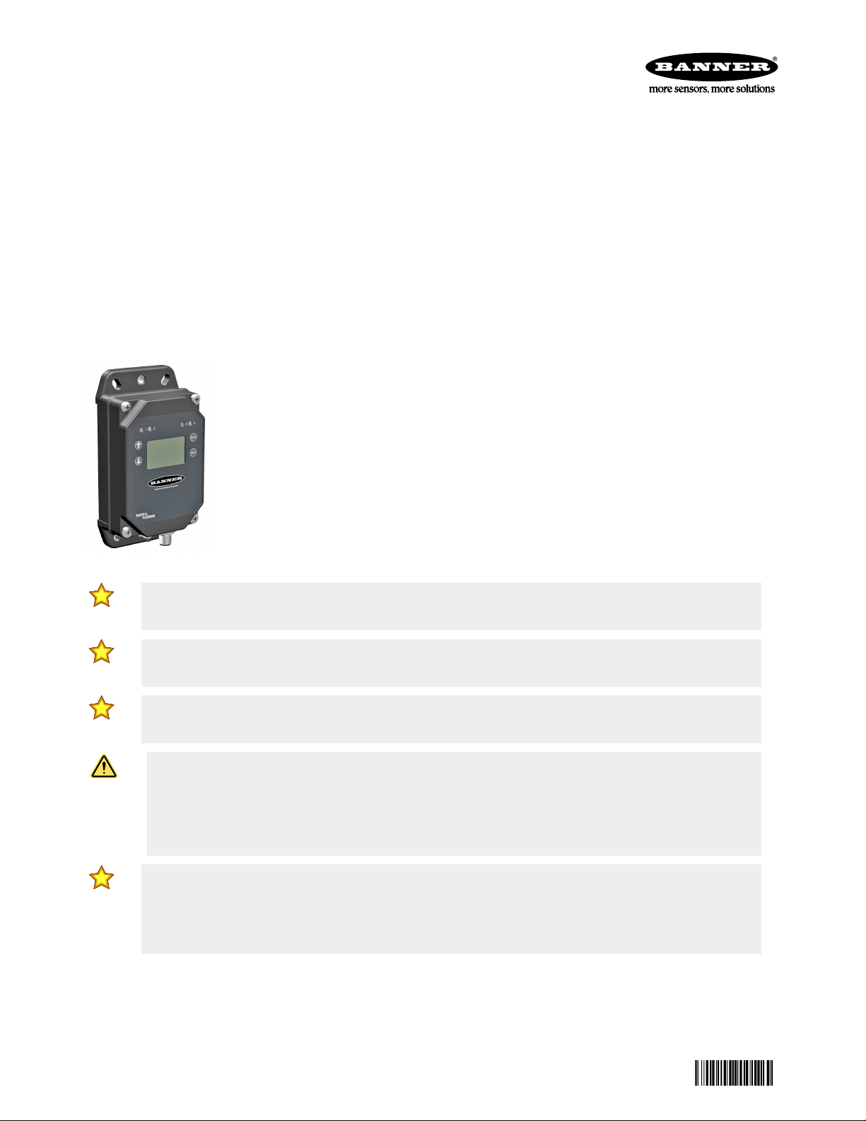
Sure Cross® DXM1200-B1 Wireless Controller
196719
Datasheet
The DXM1200-B1 Wireless Controller is an industrial wireless controller that facilitates Industrial Internet of Things (IIoT)
applications. As a communications gateway, it interfaces local serial ports, local I/O ports, and local ISM radio devices to the
Internet using a cellular connection or wired Ethernet network connection.
• High Performance Wireless Communication—Uses Sure Cross® DX80 Wireless Gateway or MultiHop radio with 900 MHz
or 2.4 GHz ISM bands available for long range communication using an internal antenna
• Flexible and Customizable—Expanded internal logic controller with action rules and ScriptBasic programming capable of
developing simple or complex solutions to process, log, and control data to/from multiple wireless radios and sensors
• Easy Installation in all Environments—IP67 housing makes installation in any location simpler by eliminating the need for a
control cabinet
• Improved Speed and Memory—Upgraded internal processor to use 2850 32-bit integer registers, 2000 floating-point
registers, and 1050 non-volatile 32-bit integer registers; expanded ScriptBasic programming capability for faster script
processing and ability to build more complex solutions with scripts
• External Communications—Optional cellular modem with internal antenna for internet
connectivity
• Industry Compatibility—Automation protocols include Modbus/TCP, Modbus RTU, and
EtherNet/IP™ for communications between PLCs, HMIs, or other local hosts
• Cloud Connectivity—Visualize data and set alarms by sending data from the DXM1200 to the
cloud either through BannerCDS.com or third-party cloud sites
• Customizable Alerts—Secure email for alarms and alerts
• Data logged to a removable SD card or sent via email
• Interactive programmable user interface with LCD and LED indicators
• Industry standard RS-485, Ethernet, and USB communication ports
Important: Please download the complete DXM1200-B1 Wireless Controller technical documentation, available
in multiple languages, from www.bannerengineering.com for details on the proper use, applications, Warnings,
and installation instructions of this device.
Important: Por favor descargue desde www.bannerengineering.com toda la documentación técnica de los
DXM1200-B1 Wireless Controller, disponibles en múltiples idiomas, para detalles del uso adecuado,
aplicaciones, advertencias, y las instrucciones de instalación de estos dispositivos.
Important: Veuillez télécharger la documentation technique complète des DXM1200-B1 Wireless Controller sur
notre site www.bannerengineering.com pour les détails sur leur utilisation correcte, les applications, les notes
de sécurité et les instructions de montage.
WARNING:
• Do not use this device for personnel protection
• Using this device for personnel protection could result in serious injury or death.
• This device does not include the self-checking redundant circuitry necessary to allow its use in
personnel safety applications. A device failure or malfunction can cause either an energized (on) or deenergized (off) output condition.
Important:
• Never operate a 1 Watt radio without connecting an antenna
• Operating 1 Watt radios without an antenna connected will damage the radio circuitry.
• To avoid damaging the radio circuitry, never apply power to a Sure Cross® Performance or Sure Cross
MultiHop (1 Watt) radio without an antenna connected.
Original Document
196719 Rev. A
27 March 2020
Page 2
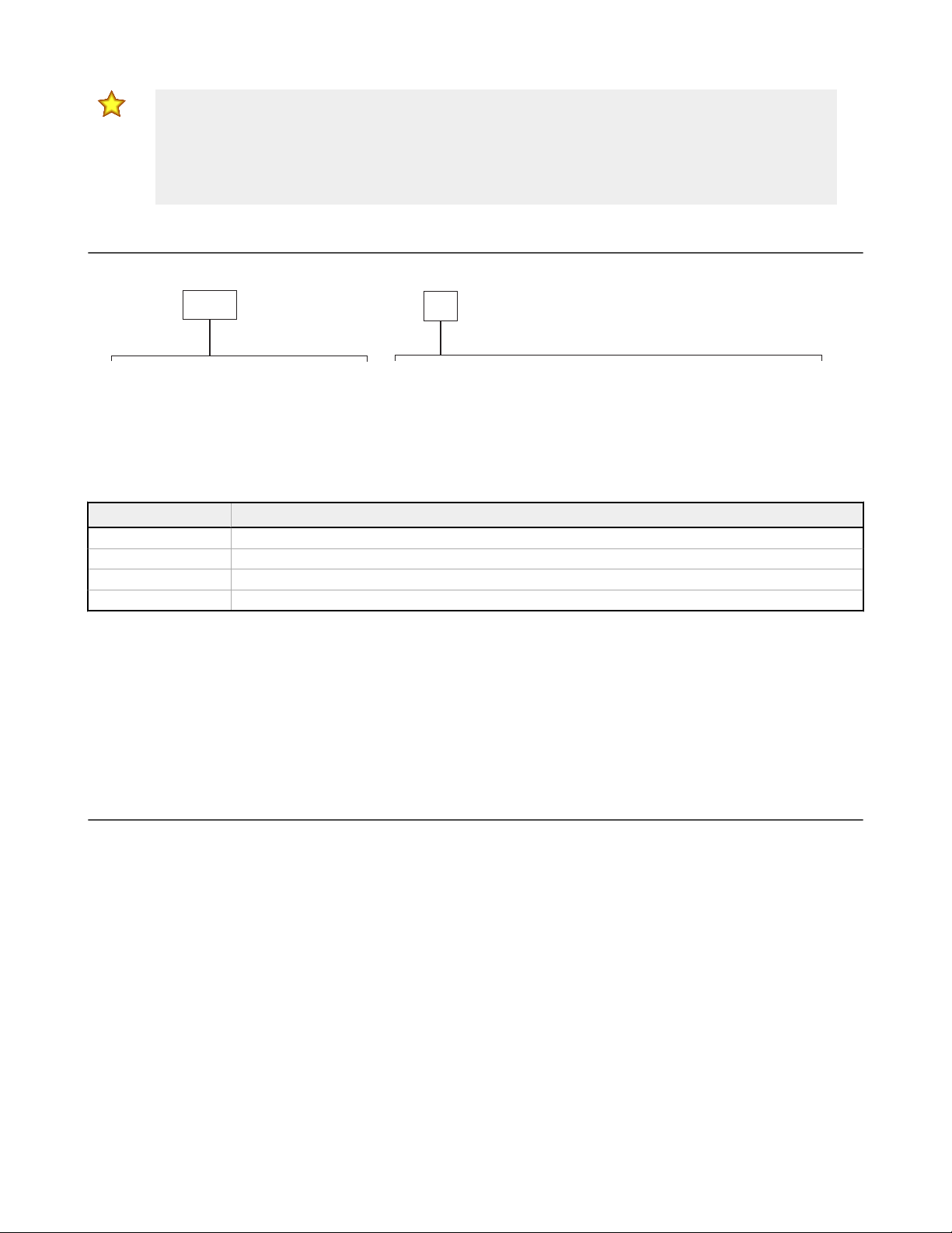
B1 =
Radio Configuration
B1
Base
DXM1200-
R1
Modbus controller for data aggregation of
sensors and wireless networks
Power: 12−30 V DC
Comms: RS-485
Blank = None
R1 = 900 MHz, 1 W PE5 Performance Radio (North America)
R2 = 900 MHz, 1 W HE5 MultiHop Data Radio (North America)
R3 = 2.4 GHz, 65 mW PE5 Performance Radio (Worldwide)
R4 = 2.4 GHz, 65 mW HE5 MultiHop Data Radio (Worldwide)
Sure Cross® DXM1200-B1 Wireless Controller
Important:
• Electrostatic discharge (ESD) sensitive device
• ESD can damage the device. Damage from inappropriate handling is not covered by warranty.
• Use proper handling procedures to prevent ESD damage. Proper handling procedures include leaving
devices in their anti-static packaging until ready for use; wearing anti-static wrist straps; and assembling
units on a grounded, static-dissipative surface.
Models
Some example models include, but are not limited to, the following:
Models Description
DXM1200-B1R1 DXM1200-B1 Wireless Controller with DX80 ISM 900 MHz radio
DXM1200-B1R2 DXM1200-B1 Wireless Controller with DX80 ISM 900 MHz MultiHop radio
DXM1200-B1R3 DXM1200-B1 Wireless Controller with DX80 ISM 2.4 GHz radio
DXM1200-B1R4 DXM1200-B1 Wireless Controller with DX80 ISM 2.4 GHz MultiHop radio
Cellular Communications—Controllers accept Banner Cellular Modems only. Adding a cellular modem to the DXM1200-B1 requires
the placement of an internal cellular antenna. Cellular modems are ordered separately as accessories under the following part
numbers:
• LTE CAT1 Verizon (United States only): SXI-LTE-001
• GSM/3G (HSPA) (International only): SXI-GSM-001
• LTE CAT-M1 AT&T (North America only): SXI-CATM1ATT-001
• LTE CAT-M1 Verizon (North America only): SXI-CATM1VZW-001
For more information, refer to the technical note Activating a Cellular Modem (p/n 205026).
DXM1200 Documentation
For more information about the DXM1200-B1 family of products, please see additional documentation and videos on the Banner
website: www.bannerengineering.com.
• DXM Wireless Controller Sell Sheet, p/n 194063
• DXM1200-B1 Wireless Controller Datasheet, p/n 196719
• DXM1200-Bx Wireless Controller Instruction Manual, p/n 216539
• DXM ScriptBasic Instruction Manual, p/n 191745
• DXM Controller
• DXM Configuration Software v4 (p/n b_4496867)
• DXM Configuration Software Instruction Manual, p/n 209933
• DXM EDS Configuration file for Allen-Bradley PLCs
• Activating a Cellular Modem (p/n b_4419353)
• Additional technical notes and videos
Technical notes,
Configuration Quick Start, p/n 191247
configuration examples, and ScriptBasic program examples are available at www.bannerengineering.com.
2 www.bannerengineering.com - Tel: + 1 888 373 6767 P/N 196719 Rev. A
Page 3
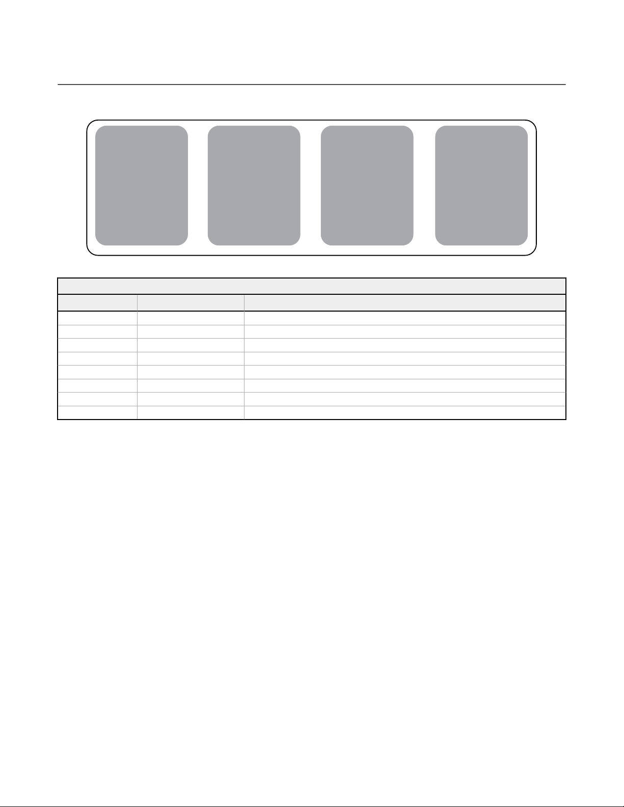
Connectivity
Cellular
Sure Cross® Radios
Ethernet
Internal Micro USB
RS-485 Master
User Interface
LCD Screen
LED Indicators
I/O
N/A
Logic Controller
Action Rules
Programming Language
Scheduler
Push to the Cloud
Data Logging
Email
Sure Cross
®
DXM1200-B1 Wireless Controller
DXM1200-Bx System Overview
Banner's DXM Logic Controller integrates Banner's wireless radio and cellular connectivity to provide a platform for the Industrial
Internet of Things (IIoT).
Figure 1. DXM1200-B1 system overview
Modbus Registers for Internal Local Registers (Modbus Slave ID 199)
Local Registers Type Description
1–845 32-bit integer Local data registers
846–849 32-bit integer Reset, Constant, Timer
851–900 32-bit non-volatile integer Data flash, non-volatile
901–1000 Reserved for internal use
1001–5000 Floating point Floating point registers, local data registers
5001–7000 32-bit integer Local data registers
7001–8000 32-bit non-volatile integer Data flash, non-volatile
> 10000 Read only virtual registers, system-level data
Connectivity—The DXM1200-B1's wired and wireless connectivity options make it easy to share data between local and remote
equipment. The cellular modem option eliminates the need for IT infrastructures to connect remote equipment for sensing and
control to IIoT cloud services. The integrated Sure Cross® wireless radio enables Modbus connectivity to remote sensors,
indicators, and control equipment. Connect directly to any PLC and/or SCADA system for easy integration into existing control or
monitoring systems.
Wired Connectivity
• Ethernet: Modbus/TCP (master/slave) or Ethernet/IP
• Field Bus: Modbus RS-485 Master
Logic Controller
concurrently. The control functions allow freedom when creating custom sensing and control sequences. The logic controller
supports the Modbus protocol standards for data management, ensuring seamless integration with existing automation systems.
File and LCD password protection is an option.
—Program the DXM1200-B1's logic controller using action rules and/or ScriptBasic language, which can execute
Wireless Connectivity
• Sure Cross Wireless Radio: DX80 900 MHz, DX80 2.4
GHz, MultiHop 900 MHz, or MultiHop 2.4 GHz
• Cellular modem: LTE (United States only) or GSM
(Outside the United States), CATM1-ATT (North America
Only) or CATM1-VZW (US Only)
P/N 196719 Rev. A www.bannerengineering.com - Tel: + 1 888 373 6767 3
Page 4

Sure Cross® DXM1200-B1 Wireless Controller
Register Mapping
• Cyclical Read rules from wireless devices or local wired
Modbus devices that include optional scaling, error
conditions, and the ability to activate a read rule
• Cyclical or Change of State Write rules to wireless
devices or local wired Modbus devices with scaling
• Modbus/TCP Master Read or Write rules for external
devices on the network
Action Rules
• Thresholds (IF/THEN/ELSE) with timers, minimum on/off
time, and logging options
• Math/Logic Rules (arithmetic and bitwise operators)
• Control Logic (logical operators and SR/T/D/JK
flops)
• Trending (multiple averaging filters)
• Tracking (counts, on/off times)
• Email
• Push data on conditions
User Interface— A simple user interface consists of an LCD screen and four LED indicators.
User programmable LCD
• Bind Sure Cross radios
• Conduct a site survey to evaluate the radio signal
• View register and output information
• View system status and configuration
notifications
integrity of radios within the network
flip
Scheduler
• Time/calendar-based events
• Holiday skips
• One-time events
• Dynamic scheduler updating
• Astronomical clock
Optional Text Programming Language
• ScriptBasic to create variables, arrays, functions, loops,
IF/THEN/ELSE, logical and arithmetic operators, API
commands, register access, string functions and
operators, time commands
Data Logging
• Cyclic data/event logging
• Email log
API Interface
• Host Initiated control
• Web service integration
User Defined LED indicators
• Indicates the status of the DXM1200-B1, processes, or
equipment
files
Applications Overview
The DXM1200-B1 is ideal for smart factory and facilities applications, including:
• Productivity solutions, such as
◦ Call for parts, service, or maintenance
◦ Pick-to-light
◦ OEE Tower light monitoring
• Predictive maintenance and continuous monitoring using
◦ Vibration and temperature monitoring
◦ Tank level monitoring
◦ Non-contact condition monitoring
• Environmental monitoring and control, such as
◦ Temperature and humidity monitoring
The DXM1200-B1 can provide visual indication using indicator lights, send email alerts, collect data, and interface with automation
systems.
Banner Connected Data Solutions (CDS)
With a few easy steps, the DXM controller can be connected and sharing data with Banner's Connected Data Solutions. This is a
web-based software platform that allows users to access, store, protect, visualize, and export critical data collected by Banner's
DXM controllers.
This software complements our wireless product portfolio and provides customers with complete end-to-end IIoT solutions to
solve the most pressing problems of the Industrial market. Visit the Connected Data Solutions site for account access and
technical support at https://bannercds.com/.
Get Solutions Up and Running Quickly
Solution Templates are available to help implement IIoT solutions with ease-no coding or expertise required. In addition, all
elements of a wireless solution from Banner-from sensor to cloud-are purpose-built to work together for easy
use.
configuration and
4 www.bannerengineering.com - Tel: + 1 888 373 6767 P/N 196719 Rev. A
Page 5

Sure Cross® DXM1200-B1 Wireless Controller
Popular solution templates include guides for the following applications:
• Vibration Monitoring and Predictive Maintenance
• Overall Equipment Effectiveness
• Tank Level Monitoring
• Temperature and Humidity Monitoring
• And more…
Make Better Data-Driven Decisions
The CDS platform is more than a dashboard. The software can provide actionable insights that allow you to solve real challenges
on the factory
floor by using analytics and visualization tools that range from graphs, gauges, status indicators, and number
displays to alarm icons, maps, and tables.
Easily organize and manage the health of various assets and processes via customizable layouts that can be constructed for
workstation screens or kiosk displays. In addition, the ability to store or export data, and analyze trends over time helps you and
the organization make better, data-driven decisions long-term.
Access the Data You Want and Get the Alerts You Need
Remotely access data anytime and anywhere.
On-demand visibility and real-time alerts allow you to remotely monitor and diagnose systems quickly, saving time and cost.
Simple data structure allows users to organize assets and facilities in a manner that best serves the needs of the business.
Maximize Uptime and Increase
Efficiency
Predictive maintenance is a key capability of Banner's IIoT solutions.
The software platform helps you use device data to predict machine maintenance requirements, which reduces unplanned
downtime, increases mean time between failure (MTBF), and reduces maintenance costs.
Specifications
MultiHop Radio with Internal Antenna Specifications
Radio Range
900 MHz, 1 Watt (Internal antenna): Up to 3.2 km (2 miles) with line of sight
2.4 GHz, 65 mW (Internal antenna): Up to 1000 m (3280 ft) with line of sight
Antenna Minimum Separation Distance
900 MHz, 150 mW and 250 mW: 2 m (6 ft)
900 MHz, 1 Watt: 4.57 m (15 ft)
2.4 GHz, 65 mW: 0.3 m (1 ft)
Radio Transmit Power
900 MHz, 1 Watt: 30 dBm (1 W) conducted (up to 36 dBm EIRP)
2.4 GHz, 65 mW: 18 dBm (65 mW) conducted, less than or equal to 20 dBm
(100 mW) EIRP
Spread Spectrum Technology
FHSS (Frequency Hopping Spread Spectrum)
1
900 MHz Compliance (1 Watt)
FCC ID UE3RM1809: FCC Part 15, Subpart C, 15.247
IC: 7044A-RM1809
IFT: RCPBARM13-2283
2.4 GHz Compliance (MultiHop)
FCC ID UE300DX80-2400: FCC Part 15, Subpart C, 15.247
Radio Equipment Directive (RED) 2014/53/EU
IC: 7044A-DX8024
Radio Packet Size (MultiHop)
900 MHz: 175 bytes (85 Modbus registers)
2.4 GHz: 75 bytes (37 Modbus registers)
1
Range depends on the environment and decreases significantly without line of sight. Always verify your wireless network's range by performing a Site Survey.
P/N 196719 Rev. A www.bannerengineering.com - Tel: + 1 888 373 6767 5
Page 6

Sure Cross® DXM1200-B1 Wireless Controller
RS-485 Communication Specifications
Communication Hardware (MultiHop RS-485)
Interface: 2-wire half-duplex RS-485
Baud rates: 9.6k, 19.2k (default), or 38.4k via DIP switches; 1200 and 2400 via the MultiHop Configuration Software
Data format: 8 data bits, no parity, 1 stop bit
Power and I/O
Supply Voltage
12 to 30 V DC (use only with a suitable Class 2 power supply (UL) or a
Limited Power Source (LPS) (CE) power supply)
Power Consumption
60 mA average at 24 V
Communication Protocols
Modbus RTU Master, Modbus/TCP, and EtherNet/IP
Construction
Polycarbonate
Connection
Integral 5-pin M12/Euro-style male quick disconnect
Logging
8 GB maximum; removable Micro SD card format
Certifications
(CE approval only
applies to 2.4 GHz
models)
Specifications
(NOM approval only
applies to 900 MHz
models)
Environmental Specifications
Operating Conditions
–20 °C to +60 °C (–4 °F to +140 °F)
95% maximum relative humidity (non-condensing)
Radiated Immunity: 3 V/m (EN 61000-4-3)
2
Security Protocols
TLS, SSL, HTTPS
Required Overcurrent Protection
WARNING: Electrical connections must be
made by qualified personnel in accordance with
local and national electrical codes and
regulations.
Overcurrent protection is required to be provided by end product
application per the supplied table.
Overcurrent protection may be provided with external fusing or via Current
Limiting, Class 2 Power Supply.
Supply wiring leads < 24 AWG shall not be spliced.
For additional product support, go to www.bannerengineering.com.
Supply Wiring (AWG) Required Overcurrent Protection (Amps)
20 5.0
22 3.0
24 2.0
26 1.0
28 0.8
30 0.5
Shock and Vibration
All models meet IEC 60068-2-6 and IEC 60068-2-27 testing criteria
Shock: 30G 11 ms duration, half sine wave per IEC 60068-2-27
Vibration: 10 Hz to 55 Hz, 0.5 mm peak-to-peak amplitude per IEC
60068-2-6
Environmental Rating
IEC IP67
2
Operating the devices at the maximum operating conditions for extended periods can shorten the life of the device.
6 www.bannerengineering.com - Tel: + 1 888 373 6767 P/N 196719 Rev. A
Page 7

4 x Ø7
170.5
90.8
50.9
2 x 1/4-20 Internal Threads
Sure Cross® DXM1200-B1 Wireless Controller
Dimensions
All measurements are listed in millimeters, unless noted otherwise.
Accessories
For a complete list of all the accessories for the Sure Cross wireless product line, please download the Banner Industrial Wireless
Accessories list (p/n b_3147091).
Cordsets
MQDC1-506—5-pin M12/Euro-style, straight, single ended, 6 ft
MQDC1-530—5-pin M12/Euro-style, straight, single ended, 30 ft
MQDC1-506RA—5-pin M12/Euro-style, right-angle, single ended, 6 ft
MQDC1-530RA—5-pin M12/Euro-style, right-angle, single ended, 30 ft
IVUC-E-406—RJ45 Ethernet to 4-pin threaded M8/Pico-style, straight, 6 ft
IVUC-E-415—RJ45 Ethernet to 4-pin threaded M8/Pico-style, straight, 15 ft
Cellular Kits
SXI-LTE-001—LTE CAT1 Verizon (United States only)
SXI-GSM-001—GSM/3G (HSPA) (International only)
SXI-CATM1ATT-001—LTE CAT-M1 AT&T (North America only)
SXI-CATM1VZW-001—LTE CAT-M1 Verizon (North America only)
Power Supplies
PSD-24-4—DC Power Supply, Desktop style, 3.9 A, 24 V dc, Class 2, 4-pin
M12/Euro-style quick disconnect (QD)
PSDINP-24-06—DC power supply, 0.63 Amps, 24 V DC, with DIN Rail
Mount, Class I Division 2 (Groups A, B, C, D) Rated
PSDINP-24-13 —DC power supply, 1.3 Amps, 24 V DC, with DIN Rail
Mount, Class I Division 2 (Groups A, B, C, D) Rated
PSDINP-24-25 — DC power supply, 2.5 Amps, 24 V DC, with DIN Rail
Mount, Class I Division 2 (Groups A, B, C, D) Rated
PSW-24-1—DC power supply with wall plug, 100-240 V AC 50/60 Hz input,
24 V DC 1 A output, UL Listed Class 2
Mounting
SMBWSQ120—Rear-mount protective metal enclosure, prevents buildup of
water or ice from interfering with performance
SMBQ240SS1—Sensor mounting plate and pivoting bracket, provides
± 20° of tilt in one axis for enhanced alignment
P/N 196719 Rev. A www.bannerengineering.com - Tel: + 1 888 373 6767 7
Page 8

Sure Cross® DXM1200-B1 Wireless Controller
Warnings
Install and properly ground a qualified surge suppressor when installing a remote antenna system. Remote antenna configurations installed without surge suppressors invalidate the
manufacturer's warranty. Keep the ground wire as short as possible and make all ground connections to a single-point ground system to ensure no ground loops are created. No surge
suppressor can absorb all lightning strikes; do not touch the Sure Cross® device or any equipment connected to the Sure Cross device during a thunderstorm.
Exporting Sure Cross® Radios. It is our intent to fully comply with all national and regional regulations regarding radio frequency emissions. Customers who want to re-export this product
to a country other than that to which it was sold must ensure the device is approved in the destination country. The Sure Cross wireless products were certified for use in these countries
using the antenna that ships with the product. When using other antennas, verify you are not exceeding the transmit power levels allowed by local governing agencies. This device has
been designed to operate with the antennas listed on Banner Engineering’s website and having a maximum gain of 9 dBm. Antennas not included in this list or having a gain greater that 9
dBm are strictly prohibited for use with this device. The required antenna impedance is 50 ohms. To reduce potential radio interference to other users, the antenna type and its gain
should be so chosen such that the equivalent isotropically radiated power (EIRP) is not more than that permitted for successful communication. Consult with Banner Engineering Corp. if
the destination country is not on this list.
Banner Engineering Corp. Limited Warranty
Banner Engineering Corp. warrants its products to be free from defects in material and workmanship for one year following the date of shipment. Banner Engineering Corp. will repair or
replace, free of charge, any product of its manufacture which, at the time it is returned to the factory, is found to have been defective during the warranty period. This warranty does not
cover damage or liability for misuse, abuse, or the improper application or installation of the Banner product.
THIS LIMITED WARRANTY IS EXCLUSIVE AND IN LIEU OF ALL OTHER WARRANTIES WHETHER EXPRESS OR IMPLIED (INCLUDING, WITHOUT LIMITATION, ANY WARRANTY OF
MERCHANTABILITY OR FITNESS FOR A PARTICULAR PURPOSE), AND WHETHER ARISING UNDER COURSE OF PERFORMANCE, COURSE OF DEALING OR TRADE USAGE.
This Warranty is exclusive and limited to repair or, at the discretion of Banner Engineering Corp., replacement. IN NO EVENT SHALL BANNER ENGINEERING CORP. BE LIABLE TO
BUYER OR ANY OTHER PERSON OR ENTITY FOR ANY EXTRA COSTS, EXPENSES, LOSSES, LOSS OF PROFITS, OR ANY INCIDENTAL, CONSEQUENTIAL OR SPECIAL DAMAGES
RESULTING FROM ANY PRODUCT DEFECT OR FROM THE USE OR INABILITY TO USE THE PRODUCT, WHETHER ARISING IN CONTRACT OR WARRANTY, STATUTE, TORT,
STRICT LIABILITY, NEGLIGENCE, OR OTHERWISE.
Banner Engineering Corp. reserves the right to change, modify or improve the design of the product without assuming any obligations or liabilities relating to any product previously
manufactured by Banner Engineering Corp. Any misuse, abuse, or improper application or installation of this product or use of the product for personal protection applications when the
product is
identified as not intended for such purposes will void the product warranty. Any modifications to this product without prior express approval by Banner Engineering Corp will
void the product warranties. All
any time. Specifications and product information in English supersede that which is provided in any other language. For the most recent version of any documentation, refer to:
www.bannerengineering.com.
For patent information, see www.bannerengineering.com/patents.
specifications published in this document are subject to change; Banner reserves the right to modify product specifications or update documentation at
Notas Adicionales
Información México: La operación de este equipo está sujeta a las siguientes dos condiciones: 1) es posible que este equipo o dispositivo no cause interferencia perjudicial y 2) este
equipo debe aceptar cualquier interferencia, incluyendo la que pueda causar su operación no deseada.
Banner es una marca registrada de Banner Engineering Corp. y podrán ser utilizadas de manera indistinta para referirse al fabricante. "Este equipo ha sido diseñado para operar con las
antenas tipo Omnidireccional para una ganancia máxima de antena de 6 dBd y Yagi para una ganancia máxima de antena 10 dBd que en seguida se enlistan. También se incluyen
aquellas con aprobación ATEX tipo Omnidireccional siempre que no excedan una ganancia máxima de antena de 6dBd. El uso con este equipo de antenas no incluidas en esta lista o
que tengan una ganancia mayor que 6 dBd en tipo omnidireccional y 10 dBd en tipo Yagi, quedan prohibidas. La impedancia requerida de la antena es de 50 ohms."
Antenas SMA Modelo
Antena, Omni 902-928 MHz, 2 dBd, junta de caucho, RP-SMA
Macho
Antena, Omni 902-928 MHz, 5 dBd, junta de caucho, RP-SMA
Macho
BWA-9O2-C
BWA-9O5-C
Antenas Tipo-N Modelo
Antena, Omni 902-928 MHz, 6 dBd, fibra de vidrio, 1800mm,
N Hembra
Antena, Yagi, 900 MHz, 10 dBd, N Hembra BWA-9Y10-A
BWA-9O6-A
Mexican Importer
Banner Engineering de Mèxico, S. de R.L. de C.V.
David Alfaro Siqueiros 103 Piso 2 Valle oriente
San Pedro Garza Garcia Nuevo Leòn, C. P. 66269
81 8363.2714
©
Banner Engineering Corp. All rights reserved
 Loading...