

Page 1
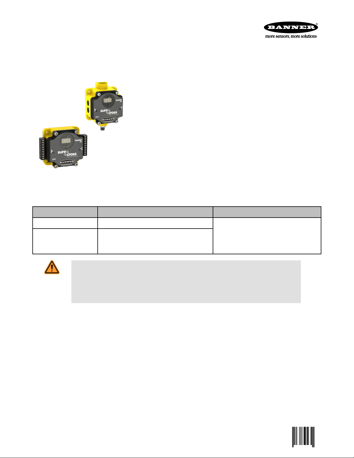
IP67 Base
IP20 Base
SureCross DX85 Modbus RTU Remote I/O Device
0 131629 2
Configurable Modbus slave remote I/O device with four sourcing discrete inputs, four sourcing discrete outputs, two 0 to 20 mA analog
inputs, and two 0 to 20 mA analog outputs
Features
The SureCross™ wireless system is a radio frequency network with integrated I/O that
can operate in most environments while eliminating the need for wiring runs. Systems are
built around a Gateway, which acts as the wireless network master device, and one or
more Nodes. A remote I/O device with a Modbus interface is used to expand the I/O of the
Gateway device or the Modbus host.
• Wireless industrial I/O device with four sourcing discrete inputs, four sourcing discrete
outputs, two 0 to 20 mA analog inputs, and 0 to 20 mA two analog outputs
• 10 to 30V dc power input
• Selectable Modbus slave address
• Modbus RTU protocol using RS-485
• The DX85...C models are certified for use in Class I, Division 2, Group A, B, C, D; and
Zone 2 (Group IIC) Hazardous Locations when properly installed in accordance with
the National Electrical Code, the Canadian Electrical Code, LCIE/ATEX, or applicable
local codes/regulations (see Specifications)
Models
Model Environmental Rating I/O
DX85M4P4M2M2 IP67, NEMA 6
IP20, NEMA 1
DX85M4P4M2M2C
WARNING: Not To Be Used for Personnel Protection
Never use this product as a sensing device for personnel protection. Doing so could lead to seri-
ous injury or death. This product does NOT include the self-checking redundant circuitry necessary to
allow its use in personnel safety applications. A sensor failure or malfunction can cause either an energized or de-energized sensor output condition.
Class I, Division 2, Group A, B, C, D Hazardous Locations (see Specifications)
Inputs: Four sourcing discrete, two 0 to 20 mA
analog
Outputs: Four sourcing discrete, two 0 to 20 mA
analog
P/N 131629 rev. G 1/25/2012
Page 2
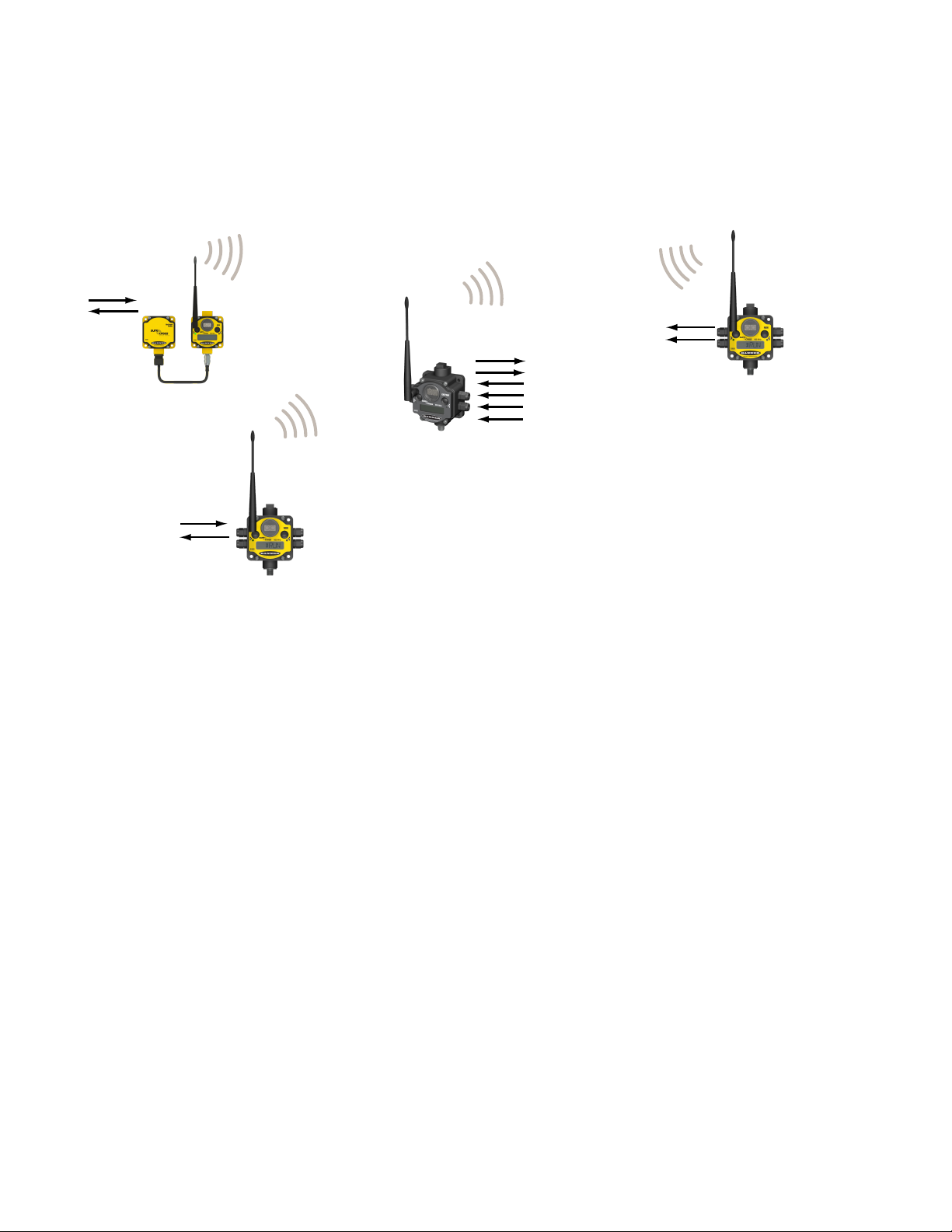
Gateway
Node
Node
FlexPower Node
and Battery Supply Module
SureCross DX85 Modbus RTU Remote I/O Device
The SureCross DX80 Wireless Network
The SureCross DX80 wireless I/O network provides reliable monitoring without the burden of wiring or conduit installation. The SureCross
wireless network can operate independently or in conjunction with a host system, PLC, and/or PC software.
Each wireless network system consists of one Gateway and one or more Nodes. Devices ship with factory defined inputs and outputs
that may be all discrete, all analog, or a mix of discrete and analog I/O.
The SureCross DX80 network is a deterministic system—the network identifies when the radio signal is lost and drives relevant outputs
to user-defined conditions. Once the radio signal is reacquired, the network returns to normal operation.
SureCross DX80 Gateways and Nodes
A Gateway acts as the master device within each radio network, initiates communication and reporting with the Nodes, and controls the
timing for the entire network.
The Gateway also holds the configuration for the network. Every wireless network must have one Gateway that schedules communication traffic and controls the I/O configuration for the network. A radio network contains only one Gateway, but can contain many Nodes.
Similar to how a gateway device on a wired network acts as a “portal” between networks, the SureCross Gateway acts as the portal
between the wireless network and the central control process.
A Node is a wireless network end-point device used to provide sensing capability in a remote area or factory. The Node collects data
from sensors and communicates the data back to the Gateway. Nodes are available in a wide variety of power or input/output options.
Each Node device can be connected to sensors or output devices and reports I/O status to the Gateway.
DX85 Modbus RTU I/O Slaves
Use the DX85 Modbus RTU I/O devices to expand the I/O of a Modbus master device. DX85s are hardwired to Modbus master devices
using RS-485 and use Modbus RTU to exchange data. DX85s are available with discrete, analog, or a mix of discrete and analog I/O.
Additional Information
For additional information, including installation and setup, weatherproofing, device menu maps, troubleshooting, and a list of accessories, refer to one of the following product manuals
• SureCross Quick Start Guide: Banner part number 128185
• SureCross Wireless I/O Network Manual: 132607
• Web Configurator Manual (used with "Pro" and DX83 models): 134421
2 www.bannerengineering.com - tel: 763-544-3164 P/N 131629 rev. G
Page 3
PWR
GND
AO2
AO1
DO4
DO3
DO2
DO1
PWR
GND
AI2
AI1
DI4
DI3
DI2
DI1
SureCross DX85 Modbus RTU Remote I/O Device
Wiring Diagrams
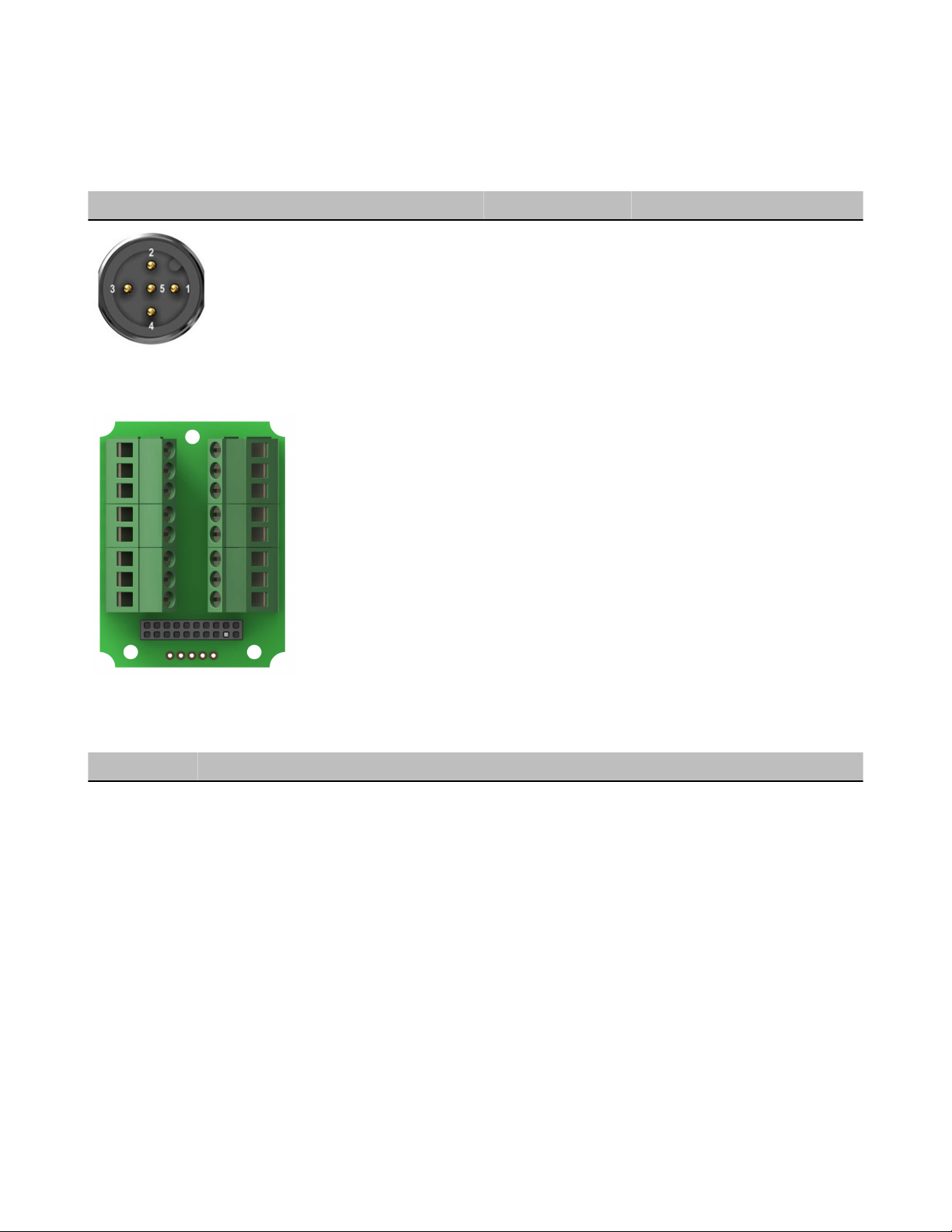
5-pin Euro-Style Hookup
Wiring the 5-pin Euro-style connector depends on the model and power requirements of the device. Connecting dc power to the communication pins will cause permanent damage.
Wire No. Wire Color Description
1 Brown 10 to 30V dc
2 White RS485 / D1 / B / +
3 Blue dc common (GND)
4 Black RS485 / D0 / A / –
5 Gray Comms Gnd
Terminal Block (IP67 Models)
AIx or Ax. Analog IN x.
AOx. Analog OUT x.
DIx. Discrete IN x.
DOx. Discrete OUT x.
GND. Ground/dc common connection.
PWR. Power, 10 to 30V dc power connection.
DX80...C Wiring
Wiring power to the DX80...C models varies depending the power requirements of the model.
Terminal Label Gateway, DX85 * 10 to 30V dc Powered Nodes Battery Powered Nodes **
V+ 10 to 30V dc 10 to 30V dc
Tx/+ RS485 / D1 / B / +
V- dc common (GND) dc common (GND) dc common (GND)
Rx/- RS485 / D0 / A / -
B+ 3.6 to 5.5V dc
* Connecting dc power to the communication pins will cause permanent damage.
** For FlexPower devices, do not apply more than 5.5V to the gray wire.
P/N 131629 rev. G www.bannerengineering.com - tel: 763-544-3164 3
Page 4

DI1
DI2
DI3
DI4
AI1
AI2
V+
V−
V−
DO1
DO2
DO3
DO4
AO1
AO2
TX/+
RX/−
V+
DIx
PWR or SPx
SureCross Device
DIx
GND
SureCross Device
DOx
GND
SureCross Device
SureCross DX85 Modbus RTU Remote I/O Device
Terminal Block (IP20 Models)
AIx or Ax. Analog IN x.
AOx. Analog OUT x.
DIx. Discrete IN x.
DOx. Discrete OUT x.
PWR. Power, 10 to 30V dc power connection.
RX/-. Serial comms line
TX/+. Serial comms line
V+. Power, 10 to 30V dc power connection.
V-. Ground/dc common connection.
Wiring Diagrams for Discrete Inputs
Connecting dc power to the communication pins will cause permanent damage. For the DX8x...C models, PWR in the wiring diagram
refers to V+ on the wiring board and GND in the wiring diagram refers to V- on the wiring board.
Discrete Input Wiring (PNP) Discrete Input Wiring (NPN)
Wiring Diagrams for Discrete Outputs
Connecting dc power to the communication pins will cause permanent damage. For the DX8x...C models, PWR in the wiring diagram
refers to V+ on the wiring board and GND in the wiring diagram refers to V- on the wiring board.
Discrete Output Wiring (PNP)
4 www.bannerengineering.com - tel: 763-544-3164 P/N 131629 rev. G
Page 5

AIx
PWR
SureCross Device
SureCross Device
dc common
external
power
AIx or Ax+
GND
SureCross Device
AIx or Ax+
SPx
AOx
PWR
GND
SureCross Device
SureCross DX85 Modbus RTU Remote I/O Device
Wiring Diagrams for Analog Inputs
Connecting dc power to the communication pins will cause permanent damage. Do not exceed analog input ratings for analog inputs.
Only connect sensor outputs to analog inputs.
Analog Input Wiring (10 to 30V dc Power)
Analog Input Wiring (Externally Powered
Sensors)
Analog Input Wiring (Switch Powered
Sensors)
(Only possible in models with switch power
(SPx) outputs)
Wiring Diagrams for Analog Outputs
Connecting dc power to the communication pins will cause permanent damage. Do not exceed analog input ratings for analog inputs.
Only connect sensor outputs to analog inputs.
Analog Output Wiring
Modbus Register Table
I/O Modbus Holding Register I/O Type Units I/O Range Holding Register
Representation
Gateway
or DX85
Any Node Min. Val-ueMax.
Value
Min.
(Dec.)
Max.
(Dec.)
1 1 1 + (Node# × 16) Discrete IN 1 - 0 1 0 1 DI1
2 2 2 + (Node# × 16) Discrete IN 2 - 0 1 0 1 DI2
3 3 3 + (Node# × 16) Discrete IN 3 - 0 1 0 1 DI3
4 4 4 + (Node# × 16) Discrete IN 4 - 0 1 0 1 DI4
5 5 5 + (Node# × 16) Analog IN 1 mA
V
6 6 6 + (Node# × 16) Analog IN 2 mA
V
0.0
0.0
0.0
0.0
20.0
10.0
20.0
10.0
0 65535 AI1
0 65535 AI2
7 7 7 + (Node# × 16) Reserved
8 8 8 + (Node# × 16) Device Message
P/N 131629 rev. G www.bannerengineering.com - tel: 763-544-3164 5
Terminal
Block La-
bels
Page 6

SureCross DX85 Modbus RTU Remote I/O Device
I/O Modbus Holding Register I/O Type Units I/O Range Holding Register
Representation
Gateway
or DX85
9 9 9 + (Node# × 16) Discrete OUT 1 - 0 1 0 1 DO1
10 10 10 + (Node# × 16) Discrete OUT 2 - 0 1 0 1 DO2
11 11 11 + (Node# × 16) Discrete OUT 3 - 0 1 0 1 DO3
12 12 12 + (Node# × 16) Discrete OUT 4 - 0 1 0 1 DO4
13 13 13 + (Node# × 16) Analog OUT 1 mA
14 14 14 + (Node# × 16) Analog OUT 2 mA
15 15 15 + (Node# × 16) Control Message
16 16 16 + (Node# × 16) Reserved
Some analog I/O models may use milliamps or voltage, depending on the model. Check the models table (on page 1) of your product's
data sheet to determine which model you have.
Any Node Min. Val-ueMax.
Value
0.0
V
V
0.0
0.0
0.0
20.0
10.0
20.0
10.0
Min.
(Dec.)
0 65535 AO1
0 65535 AO2
Max.
(Dec.)
Terminal
Block La-
bels
Device Configuration
Setting the Slave ID on a DX85 Remote I/O Device
On a DX85 Modbus RTU Remote I/O device, use the rotary dials to set the device’s Slave ID.
In Rotary Dial Decimal Mode, the left dial acts as the left digit and the right dial acts as the right
digit, allowing the Slave ID to be set from 01 through 99.
In Rotary Dial Hex Mode, the left dial acts as the left digit and the right dial acts as the right digit,
allowing the Slave ID to be set from 01 through F7 for a total of 247 slaves.
The 12 I/O DX85 models use Rotary Dial Decimal Mode and do not have a DIP switch selection
for this option.
To configure the DX85 using the UCT, the DX85's Slave ID must be set to 01.
DIP Switch Changes
Before making any changes to the DIP switch positions, disconnect
the power. For devices with batteries integrated into the housing,
remove the battery for at least one minute.
DIP switch changes will not be recognized if power isn't cycled to
the device.
Accessing the Internal DIP Switches
To access the internal DIP switches, follow these steps:
1. Unscrew the four screws that mount the cover to the bottom housing.
2. Remove the cover from the housing without damaging the ribbon cable or the pins the cable plugs into.
3. Gently unplug the ribbon cable from the board mounted into the bottom housing. For integrated battery models (no ribbon cable) and
Class I, Division 2 certified devices (ribbon cable is glued down), skip this step.
4. Remove the black cover plate from the bottom of the device's cover.
6 www.bannerengineering.com - tel: 763-544-3164 P/N 131629 rev. G
Page 7

SureCross DX85 Modbus RTU Remote I/O Device
The DIP switches are located behind the rotary dials. After making the necessary changes to the DIP switches, place the black cover plate back into position and gently push into place. Plug the ribbon cable in after verifying that
the blocked hole lines up with the missing pin. Mount the cover back onto the
housing.
DIP Switch Settings for a DX85
Use the DIP switches 1 through 4 on the board to set the baud rate and parity and DIP switch 5 to set the rotary dial mode.
DIP Switches
1 2 3 4 5
Baud Rate: 19200 OFF* OFF*
Baud Rate: 38400 OFF ON
Baud Rate: 9600 ON OFF
Baud Rate: 19200 ON ON
Parity: None OFF* OFF*
Parity: Even OFF ON
Parity: Odd ON OFF
Parity: None ON ON
Rotary Dial Decimal Mode OFF*
Rotary Dial Hex Mode ON
* Default configuration
Verify Communications on the DX85 Modbus RTU Remote I/O
After powering up, verify the DX85 is communicating properly. LED 1 should be on and green.
Status LED 1 LED 2
Power ON Green ON -
Device error, contact factory Red flashing Red flashing
Modbus communication active
Modbus communication error - Red flashing
- Yellow flashing
The Modbus communication LEDs refer to the communication between the DX85 and what it is connected to (host system, Gateway,
Data Radio, etc).
P/N 131629 rev. G www.bannerengineering.com - tel: 763-544-3164 7
Page 8

SureCross DX85 Modbus RTU Remote I/O Device
Specifications
General
Power*
Requirements: +10 to 30V dc (For European applications: +10 to 24V dc, ± 10%). (See UL section below
for any applicable UL specifications)
Consumption: Less than 1.4 W (60 mA) at 24V dc
Housing
Polycarbonate
Weight: 0.26 kg (0.57 lbs)
Mounting: #10 or M5 (M5 hardware included)
Max. Tightening Torque: 0.56 N·m (5 in·lbf)
Inputs and Outputs
Discrete Inputs
Rating: 3 mA max current at 30V dc
ON Condition: Greater than 8V
OFF Condition: Less than 5V
Discrete Outputs
ON Condition: Supply minus 2V
OFF Condition: Less than 2V
Output State Following Timeout: OFF
Discrete Output Rating (PNP)
100 mA max current at 30V dc
ON-State Saturation: Less than 3V at 100 mA
OFF-state Leakage: Less than 10 μA
Interface
Indicators: Two bi-color LEDs
Wiring Access
Four PG-7, One 1/2-inch NPT, One 5-pin Euro-style
male connector
* For European applications, power the DX80 from a Limited Power Source as defined in EN 60950-1.
Analog Inputs and Outputs
Rating: 24 mA
Input Impedance: 100 Ohms
Accuracy: 0.1% of full scale +0.01% per °C
Resolution: 12-bit
To verify the analog input's impedance, use an Ohm meter to
measure the resistance between the analog input terminal (AIx)
and the ground (GND) terminal.
Communication
Hardware (RS-485)
Interface: 2-wire half-duplex RS-485
Baud Rates: 9.6k, 19.2k (default), or 38.4k
Data Format: 8 data bits, no parity, 1 stop bit
Environmental
Rating
Rating for DX85 models:IEC IP67; NEMA 6; (See UL
section below for any applicable UL specifications)
Rating for DX85...C models: IEC IP20; NEMA 1 (In a
Shock and Vibration
IEC 68-2-6 and IEC 68-2-7
Shock: 30g, 11 millisecond half sine wave, 18 shocks
Vibration: 0.5 mm p-p, 10 to 60 Hz
suitable enclosure: Class I, Division 2, Group A, B, C,
D; T4 −40 to 80° C)
Operating Temperature: −40 to +85° C (Electronics);
−20 to +80° C (LCD)
Operating Humidity: 95% max. relative (non-condens-
ing)
Radiated Immunity: 10 V/m, 80-2700 MHz
(EN61000-6-2)
Refer to the SureCross™ DX80 Wireless I/O Network product manual, Banner p/n 132607, for installation and waterproofing instructions.
Operating the devices at the maximum operating conditions for extended periods can shorten the life of the device.
8 www.bannerengineering.com - tel: 763-544-3164 P/N 131629 rev. G
Page 9

SureCross DX85 Modbus RTU Remote I/O Device
Certifications
DX8x...C (External Wiring Terminal Models)
CSA: Class I, Division 2, Groups A, B, C, D (Ex/A Ex nA II T4); Certificate: 1921239
LCIE/ATEX: Zone 2 (II 3G / Ex nA IIC); Certificate: LCIE 10 ATEX 1012 X
UL Listing
Maximum ambient temperature: 70°C
Mounting instructions: See document 132607
Power rating: 10 to 30V dc, UL Class 2
Enclosure environmental rating: UL Type 1
Included with Device (DX85 and DX85...C Models)
The following items ship with the DX85 models.
Included with Device Model Qty Item
DX80 Access Hardware Kit * BWA-HW-002 4 Plastic threaded plugs, PG-7
4 Nylon gland fittings, PG-7
4 Hex nuts, PG-7
1 Plug, 1/2" NPT
1 Nylon gland fitting, 1/2" NPT
Mounting Hardware Kit BWA-HW-001 4 Screw, M5-0.8 x 25mm, SS
4 Screw, M5-0.8 x 16mm, SS
4 Hex nut, M5-0.8mm, SS
4 Bolt, #8-32 x 3/4", SS
PTFE Tape * BWA-HW-003 1 PTFE Tape
SureCross Literature CD 79685 1 SureCross Literature CD
Cable MQDC1-506 1 Cable, 5-pin Euro (single ended), Straight, 2m
BWA-HW-011 1 IP20 Screw Terminal Headers (2 pack) (ships with DX85...C
models only)
* Not included with DX85...C models.
Warnings
The manufacturer does not take responsibility for the violation of any warning listed in this document.
Make no modifications to this product. Any modifications to this product not expressly approved by Banner Engineering could void the
user’s authority to operate the product. Contact the Factory for more information.
All specifications published in this document are subject to change. Banner reserves the right to modify the specifications of products without notice. Banner Engineering reserves the right to update or change documentation at any time. For the most recent version of
any documentation, refer to our website: www.bannerengineering.com. © 2006-2010 Banner Engineering Corp. All rights reserved.
P/N 131629 rev. G www.bannerengineering.com - tel: 763-544-3164 9
Page 10

SureCross DX85 Modbus RTU Remote I/O Device
Limited Warranty
Banner Limited Warranty
Banner Engineering Corp. warrants its products to be free from defects in material and workmanship for one year following the date of
shipment. Banner Engineering Corp. will repair or replace, free of charge, any product of its manufacture which, at the time it is returned
to the factory, is found to have been defective during the warranty period. This warranty does not cover damage or liability for misuse,
abuse, or the improper application of the Banner product.
THIS LIMITED WARRANTY IS EXCLUSIVE AND IN LIEU OF ALL OTHER WARRANTIES WHETHER EXPRESS OR IMPLIED (INCLUDING, WITHOUT LIMITATION, ANY WARRANTY OF MERCHANTABILITY OR FITNESS FOR A PARTICULAR PURPOSE),
AND WHETHER ARISING UNDER COURSE OF PERFORMANCE, COURSE OF DEALING OR TRADE USAGE.
This Warranty is exclusive and limited to repair or, at the discretion of Banner Engineering Corp., replacement. IN NO EVENT SHALL
BANNER ENGINEERING CORP. BE LIABLE TO BUYER OR ANY OTHER PERSON OR ENTITY FOR ANY EXTRA COSTS, EXPENSES, LOSSES, LOSS OF PROFITS, OR ANY INCIDENTAL, CONSEQUENTIAL OR SPECIAL DAMAGES RESULTING FROM
ANY PRODUCT DEFECT OR FROM THE USE OR INABILITY TO USE THE PRODUCT, WHETHER ARISING IN CONTRACT OR
WARRANTY, STATUTE, TORT, STRICT LIABILITY, NEGLIGENCE, OR OTHERWISE.
Banner Engineering Corp. reserves the right to change, modify or improve the design of the product without assuming any obligations
or liabilities relating to any product previously manufactured by Banner Engineering Corp.
Contact Us
For more information: Contact your local Banner representative or Banner Corporate Offices around the world.
Corporate Headquarters: Banner Engineering Corp. 9714 Tenth Ave. North, Mpls., MN 55441, Tel: 763-544-3164, www.bannerengin-
eering.com, sensors@bannerengineering.com
Europe: Banner Engineering Europe Park Lane, Culliganlaan 2F, Diegem B-1831 BELGIUM,Tel: 32-2 456 07 80, Fax: 32-2 456 07 89,
www.bannereurope.com, mail@bannereurope.com
Latin America: Contact Banner Engineering Corp. (US) or e-mail Mexico: mexico@bannerengineering.com; or Brazil: brasil@banner-
engineering.com
Asia:
Banner Engineering China Shanghai Rep Office Rm. G/H/I, 28th Flr. Cross Region Plaza No. 899, Lingling Road, Shanghai 200030
CHINA, Tel: 86-21-54894500, Fax: 86-21-54894511, www.bannerengineering.com.cn, sensors@bannerengineering.com.cn
Banner Engineering Japan Cent-Urban Building 305 3-23-15, Nishi-Nakajima Yodogawa-Ku, Osaka 532-0011 JAPAN, Tel:
81-6-6309-0411, Fax: 81-6-6309-0416, www.bannerengineering.co.jp, mail@bannerengineering.co.jp
Banner Engineering Int’l Incorporated Taiwan Rep. Office 8F-2, No. 308, Sec. 1, Neihu Rd. Taipei, Taiwan 114 Phone: +886 2 8751
9966 #15 | Fax: +886 2 8751 2966, www.bannerengineering.com.tw, info@bannerengineering.com.tw
Banner Engineering India Pune Head Quarters Office, No. 1001 Sai Capital, Opp. ICC Senapati Bapat Road, Pune 411016 INDIA, Tel:
91-20-66405624, Fax: 91-20-66405623, www.bannerengineering.co.in, india@bannerengineering.com
 Loading...