

Page 1
Gateway
Node
Node
FlexPower Node
and Battery Supply Module
SureCross DX83 Ethernet Bridge
0 131934 3
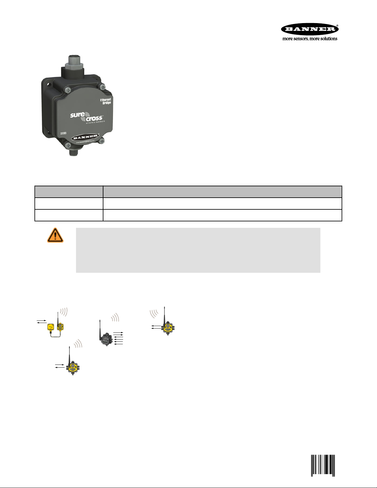
DX83 Ethernet Bridge for industrial network configuration and communication
The SureCross® DX80 is a radio frequency network system built around a Gateway and one
or more Nodes. The DX83 Ethernet Bridge connects between a DX80 Gateway device and a
computer. Once connected, the DX80 system may be configured using any Web browser.
The DX83 Ethernet Bridge also allows a host connection using Modbus/TCP.
• 10 to 30V dc power input
• Modbus serial interface and Ethernet interface
• XML formatted files store multiple configurations of the DX80 system
• IP address accessible configuration Web page
For additional information, the most recent version of all documentation, and a complete list of accessories, refer to Banner Engineering's
website, www.bannerengineering.com/surecross.
Models Features
DX83T
Modbus RTU via RS-485 (Modbus/TCP or EtherNet/IP™ communication protocol)
DX83A Modbus/TCP protocol (Configuration capability using the Web Configurator)
WARNING: Not To Be Used for Personnel Protection
Never use this device as a sensing device for personnel protection. Doing so could lead to serious
injury or death. This device does not include the self-checking redundant circuitry necessary to allow its
use in personnel safety applications. A sensor failure or malfunction can cause either an energized or deenergized sensor output condition.
The SureCross® DX80 Wireless Network
The SureCross® DX80 wireless I/O network provides reliable monitoring without wiring or conduit installation. The SureCross wireless
network operates independently or in conjunction with a host system,
PLC, and/or PC software.
Each wireless network system consists of one Gateway and one or
more Nodes. Devices ship with factory-defined discrete, analog, or a
mix of discrete and analog inputs and outputs.
The SureCross® DX80 network is a deterministic system—the network identifies when the radio signal is lost and drives relevant outputs to user-defined conditions. After the radio signal is reacquired,
the network returns to normal operation.
SureCross® DX80 Gateways and Nodes
A Gateway is the master device within each radio network. Every wireless network must have one Gateway, which schedules communication traffic and controls the I/O configuration for the network, and one or more Nodes. Similar to how a gateway device on a wired
network acts as a “portal” between networks, the SureCross Gateway acts as the portal between the wireless network and the host
controller. When the Gateway, using its Modbus RTU RS-485 connection, is a Modbus slave to a Modbus RTU host controller, the wireless network may contain up to 47 Nodes in a single wireless network. The Gateway holds the Modbus registers of all wireless devices
within the network.
P/N 131934 Rev. E 5/14/2013
Page 2
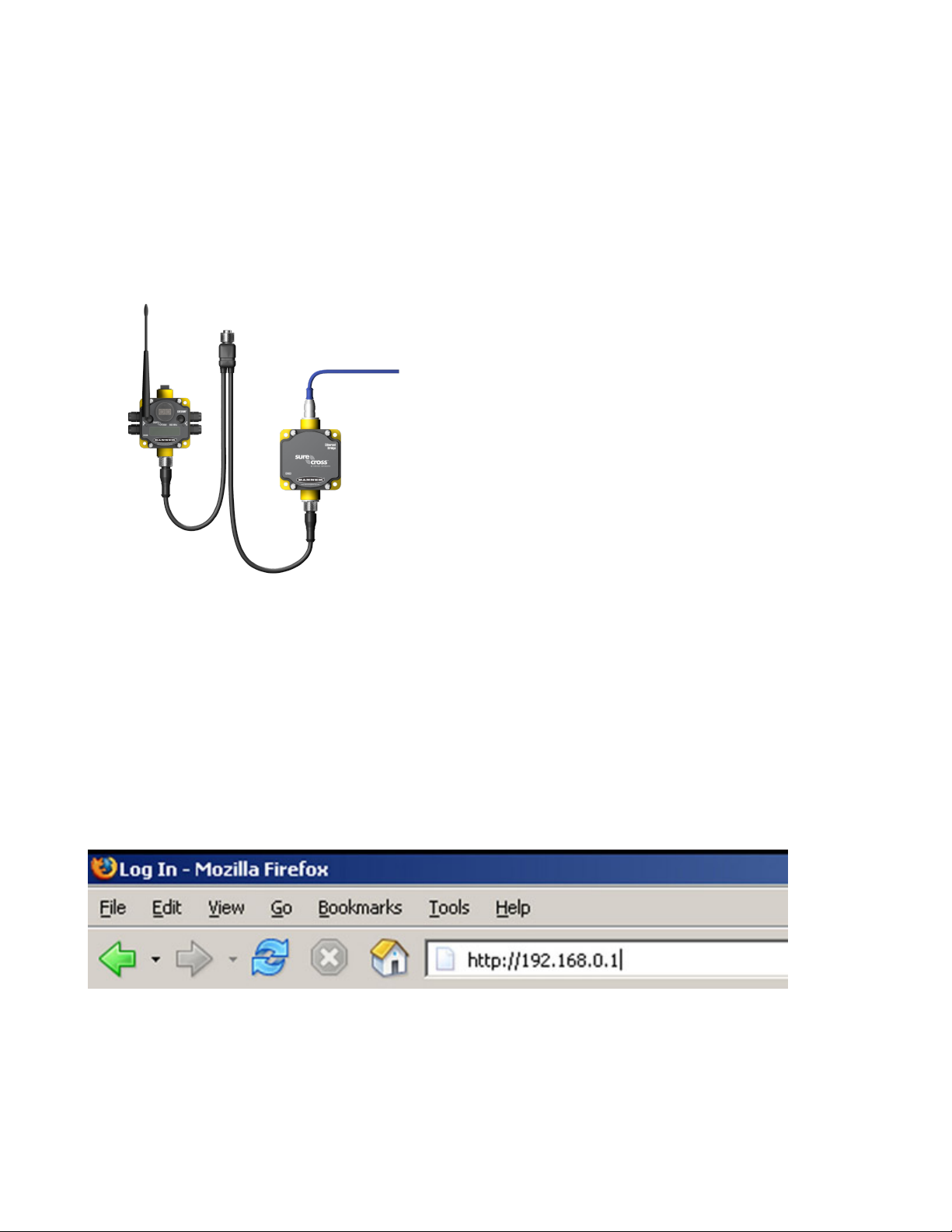
DX80 Gateway
Power
DX83 Ethernet Bridge
Ethernet cable (crossover cable
when connecting to a computer,
straight cable when connecting to
a hub or switch box.
CSRB-M1250M125.47M125.73 5-pin splitter cable (black); OR
CSB-M1240M1241 4-pin splitter cable (yellow)
SureCross DX83 Ethernet Bridge
A Node is a wireless network end-point device used to provide sensing capability in a remote area or factory. The Node collects data
from sensors and communicates the data back to the Gateway. Nodes are available in a wide variety of power or input/output options.
DX83 Ethernet Bridge Overview
The DX83 Ethernet Bridge adds the Web page configuration ability to a Gateway-Node wireless network as well as the ability to interface
to Ethernet using Modbus/TCP or EtherNet/IP protocols. A DX83 Ethernet Bridge connected to a DX80 Gateway functions like a DX80
GatewayPro while allowing the Gateway to have I/O points. There are two basic DX83 models:
• DX83T. The T model acts as a protocol converter only, offering the Modbus/TCP or EtherNet/IP communication protocols.
• DX83A. The A model includes DX80 wireless network configuration, Modbus RTU master, Modbus/TCP client/server, Script Basic, email, data logging, and trending.
Connect a DX83 Ethernet Bridge to a host system using the industrial Ethernet connection on the DX83. To connect the DX83 directly to the host system without using an Ethernet switchbox/hub,
some host systems may require a crossover cable.
By default, the DX83 is configured to use Modbus/TCP. To use
EtherNet/IP, you must connect the DX83 to a managed switch and
you must use the Web Configuration tool to select EtherNet/IP
(see SureCross Wireless I/O Product Manual or Host Configura-
tion Manual).
Logging into the Web Configurator
The SureCross® Pro and DX83 Ethernet Bridge devices use an XML file to configure the network. To access the XML file, use any web
browser set up for a direct connection to the Internet. If problems occur while connecting, verify the browser is not set to use a proxy
server.
When connecting to the Ethernet Bridge, GatewayPro, or MultiHop Pro directly from a host computer, a crossover Ethernet cable is
required; when connecting through a switch or Ethernet hub, use a standard Ethernet cable.
• The factory default IP address for the devices is: 192.168.0.1.
To change the device’s default IP address, first set up the host PC with an IP address different from the Ethernet Bridge, GatewayPro, or
MultiHop Pro IP addresses. (Please refer to Banner document 133116 for instructions on setting up the host computer’s network IP address.) After changing the host’s IP address, open a web browser and log into the Ethernet Bridge, GatewayPro, or MultiHop Pro by
typing the IP address in the browser location window: http://192.168.0.1.
After entering the IP address, the home web page for the SureCross device displays. To log in, click on any tab at the top of the page. To
log out, close the browser.
Admin-level access allows administrators to set up system users and their passwords. Admin-level access is also required to change the
IP address of the system. For Admin-level access, enter the following as the user name and password:
• User name: root
• Password: sxi
For user-level access, enter the following as the user name and password.
2 www.bannerengineering.com - tel: 763-544-3164 P/N 131934 Rev. E
Page 3

1
2
3
4
5
Communication pins
SureCross DX83 Ethernet Bridge
• User name: system
• Password: admin
5-pin Euro-Style Hookup
Wiring the 5-pin Euro-style connector depends on the model and power requirements of the device. Connecting dc power to the communication pins will cause permanent damage.
Wire No. Wire Color RS-485 Mode RS-232 Mode
1 Brown 10 to 30V dc 10 to 30V dc
2 White RS485 / D1 / B / + RS-232 Tx
3 Blue dc common (GND) dc common (GND)
4 Black RS485 / D0 / A / – RS-232 Rx
5 Gray Comms Gnd Comms Gnd
Industrial Ethernet Wiring
Use the 4-pin industrial Ethernet connection to connect the radio network to an Ethernet-based host system.
Wire No. Wire Color Description
1 White/Orange +Tx
2 White/Blue +Rx
3 Orange -Tx
4 Blue -Rx
Serial Communication Configuration for DX83s
The DX83 Ethernet Bridge uses jumpers to select between RS-485 and RS-232 communications.
Install the four jumpers across the two top rows of pins for RS-485 and across the bottom two rows of pins for RS-232.
P/N 131934 Rev. E www.bannerengineering.com - tel: 763-544-3164 3
Page 4

SureCross DX83 Ethernet Bridge
Additional Information
For additional information, including installation and setup, weatherproofing, device menu maps, troubleshooting, and a list of accessories, refer to one of the following product manuals
• SureCross Quick Start Guide: Banner part number 128185
• SureCross Wireless I/O Network Manual: 132607
• Web Configurator Manual (used with "Pro" and DX83 models): 134421
• Host Configuration Manual 132114
Modbus Register Table
I/O Point Modbus Holding Register
Gateway Any Node
1 1 1 + (Node# × 16)
2 2 2 + (Node# × 16)
3 3 3 + (Node# × 16)
4 4 4 + (Node# × 16)
5 5 5 + (Node# × 16)
6 6 6 + (Node# × 16)
7 7 7 + (Node# × 16)
8 8 8 + (Node# × 16)
9 9 9 + (Node# × 16)
10 10 10 + (Node# × 16)
11 11 11 + (Node# × 16)
12 12 12 + (Node# × 16)
13 13 13 + (Node# × 16)
14 14 14 + (Node# × 16)
15 15 15 + (Node# × 16)
16 16 16 + (Node# × 16)
Specifications
General Communication
Power*
Requirements: +10 to 30V dc (Outside the USA: +12 to
24V dc, ±10%). (See UL section below for any applicable UL specifications)
Consumption: Less than 1.7 W (70 mA) at 24V dc
Housing
Polycarbonate housing and rotary dial cover; polyester
labels; EDPM rubber cover gasket; nitrile rubber, nonsulphur cured button covers
Weight: 0.26 kg (0.57 lbs)
Mounting: #10 or M5 (SS M5 hardware included)
Max. Tightening Torque: 0.56 N·m (5 lbf·in)
* For European applications, power the DX80 from a Limited Power Source as defined in EN 60950-1.
Hardware (RS-485)
Interface: 2-wire half-duplex RS-485
Baud rates: 9.6k, 19.2k (default), or 38.4k
Data format: 8 data bits, no parity, 1 stop bit
Modbus/TCP, EtherNet/IP
Interface: 4-wire Industrial Ethernet
Data rate: 10/100 Mbps, full or half duplex, auto sens-
ing
4 www.bannerengineering.com - tel: 763-544-3164 P/N 131934 Rev. E
Page 5

SureCross DX83 Ethernet Bridge
Environmental
Rating
IEC IP67; NEMA 6; (See UL section below for any applicable UL specifications)
Operating Temperature
−40 to +85 °C (Electronics); −20 to +80 °C (LCD)
Operating Humidity
95% max. relative (non-condensing)
Radiated Immunity
10 V/m, 80-2700 MHz (EN61000-6-2)
Shock and Vibration
IEC 68-2-6 and IEC 68-2-7
Shock: 30g, 11 millisecond half sine wave, 18 shocks
Vibration: 0.5 mm p-p, 10 to 60 Hz
Operating the devices at the maximum operating conditions for extended periods can shorten the life of the device.
Included with Device (DX83 Models)
The following items ship with the DX83 Ethernet Bridge.
• BWA-HW-001: Mounting Hardware Kit, containing four M5-0.8 x 25mm SS screws, four M5-0.8 x 16mm SS screws, four M5-0.8mm
SS hex nuts, and four #8-32 x 3/4" SS bolts
• BWA-EX2M: Ethernet crossover cable, M12 industrial/RJ45, 2 meter
Splitter Cables
Part No. Model No. Description
83265 CSRB-
M1250M125.47M125.73
Splitter cable, 5-pin Euro-style QD, No trunk male, two female
branches, black (shown).
Use to split power between two FlexPower or solar powered
devices. DO NOT use this cable to connect a FlexPower devices to a 10–30V dc powered device.
75286 CSB-M1240M1241 Splitter cable, 4-pin Euro-style QD, No trunk male, two female
branches, yellow (not shown).
Used to split power between two 10–30V dc powered devices,
such as a data radio and Gateway, or between a DX85 and
Gateway.
13805 CSRB-
M1253.28M1253.28M1253.28
14642 BWA-HW-026 Splitter cable, wall wart for external power split to 5-pin Euro-
13250 BWA-DRSPLITTER Splitter cable, DB9 Female (RS232) trunk to 5-pin Euro-style
Splitter cable, for dual power sources, 5-pin Euro female to 2
5-pin Euro males
Used to connect one FlexPower device (data radio, FlexPowered Gateway, etc) to two power sources, such as the FlexPower Solar Supply and DX81P6 Battery Pack.
style male and 5-pin Euro female (to power a M-H at 1 Watt
while configuring it through the MHCT)
male and female
Ethernet Cables
Part No. Model No. Description
77669 BWA-E2M Ethernet cable, RSCD RJ45 440, 2M
78469 BWA-E8M Ethernet cable, RSCD RJ45 440, 8M
78467 BWA-EX2M Ethernet cable, crossover, RSCD RJ45CR 440, 2M
Use a crossover cable to connect the DX80 GatewayPro or DX83 Ethernet Bridge to a host system without using an Ethernet switchbox
or hub. When using a switchbox or hub, use a straight cable.
P/N 131934 Rev. E www.bannerengineering.com - tel: 763-544-3164 5
Page 6

SureCross DX83 Ethernet Bridge
Warnings
The manufacturer does not take responsibility for the violation of any warning listed in this document. Make no modifications to this
product. Any modifications to this product not expressly approved by Banner Engineering could void the user’s authority to operate the
product. All specifications published in this document are subject to change. Banner reserves the right to modify product specifications or to update documentation at any time. For the most recent version of any documentation, refer to: www.bannerengineering.com.
© 2006-2013 Banner Engineering Corp. All rights reserved.
Banner Engineering Corp Limited Warranty
Banner Engineering Corp. warrants its products to be free from defects in material and workmanship for one year following the date of
shipment. Banner Engineering Corp. will repair or replace, free of charge, any product of its manufacture which, at the time it is returned
to the factory, is found to have been defective during the warranty period. This warranty does not cover damage or liability for misuse,
abuse, or the improper application or installation of the Banner product.
THIS LIMITED WARRANTY IS EXCLUSIVE AND IN LIEU OF ALL OTHER WARRANTIES WHETHER EXPRESS OR IMPLIED (INCLUDING, WITHOUT LIMITATION, ANY WARRANTY OF MERCHANTABILITY OR FITNESS FOR A PARTICULAR PURPOSE), AND
WHETHER ARISING UNDER COURSE OF PERFORMANCE, COURSE OF DEALING OR TRADE USAGE.
This Warranty is exclusive and limited to repair or, at the discretion of Banner Engineering Corp., replacement. IN NO EVENT SHALL
BANNER ENGINEERING CORP. BE LIABLE TO BUYER OR ANY OTHER PERSON OR ENTITY FOR ANY EXTRA COSTS, EXPENSES, LOSSES, LOSS OF PROFITS, OR ANY INCIDENTAL, CONSEQUENTIAL OR SPECIAL DAMAGES RESULTING FROM ANY
PRODUCT DEFECT OR FROM THE USE OR INABILITY TO USE THE PRODUCT, WHETHER ARISING IN CONTRACT OR WARRANTY, STATUTE, TORT, STRICT LIABILITY, NEGLIGENCE, OR OTHERWISE.
Banner Engineering Corp. reserves the right to change, modify or improve the design of the product without assuming any obligations or
liabilities relating to any product previously manufactured by Banner Engineering Corp.
www.bannerengineering.com - tel: 763-544-3164
 Loading...