

Page 1

SureCross Web Configurator
rev. - 2/14/2012
134421
Page 2

Contents
Contents
Web Configurator ......................................................................................................................................3
Logging into the Web Configurator ......................................................................................................................................3
Changing the Device's IP Address .............................................................................................................................4
Selecting a Host Communication Protocol ..................................................................................................................5
Get ALL .......................................................................................................................................................................5
Change, Refresh, Send, and Update Commands ......................................................................................................6
RF Devices Tab ...................................................................................................................................................................6
Select Models .............................................................................................................................................................6
Configure Points .........................................................................................................................................................9
Expanded Configure Points ......................................................................................................................................11
I/O Linking .................................................................................................................................................................17
Scaling ......................................................................................................................................................................18
Remote I/O ................................................................................................................................................................19
Network Tab ......................................................................................................................................................................25
Modbus Data Submenu ............................................................................................................................................25
Modbus RTU Setup Submenu ..................................................................................................................................29
Modbus TCP Setup Submenu ..................................................................................................................................33
System Tab ........................................................................................................................................................................38
Data Submenu ..........................................................................................................................................................38
Action Rules Submenu .............................................................................................................................................41
Setup Submenu ........................................................................................................................................................45
Advanced Tab ....................................................................................................................................................................50
Scheduler Submenu .................................................................................................................................................50
Data Logger Submenu ..............................................................................................................................................54
E-mail Alerts Submenu .............................................................................................................................................58
Script BASIC Submenu .............................................................................................................................................62
Basic Configuration Examples ...........................................................................................................................................64
Setting up the Devices ..............................................................................................................................................65
Configuring I/O ..........................................................................................................................................................65
Linking I/O .................................................................................................................................................................66
Link Timeouts ............................................................................................................................................................67
System Network Settings ..........................................................................................................................................68
Advanced Configuration ....................................................................................................................................................69
Thresholds ................................................................................................................................................................70
Data and Event Logging ...........................................................................................................................................70
Scheduling ................................................................................................................................................................72
Trending Data ...........................................................................................................................................................73
Scaling ......................................................................................................................................................................74
Troubleshooting .................................................................................................................................................................75
Restoring Factory Default Settings ...........................................................................................................................75
Error Codes ...............................................................................................................................................................75
2 rev. -
Page 3
Web Configurator
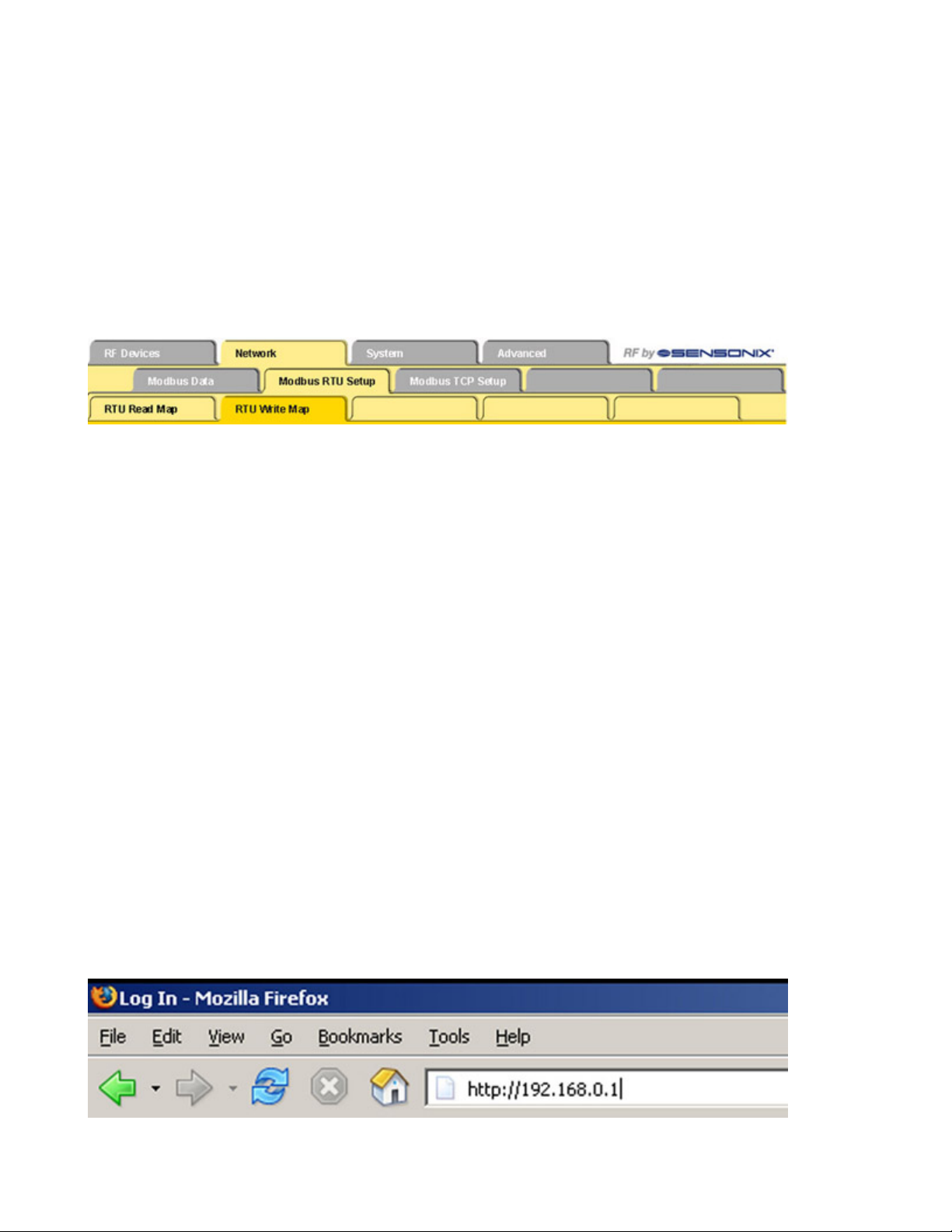
The SureCross™ DX80 GatewayPro and DX83 Ethernet Bridge devices use an XML file to configure the network. To access the XML
file, use any web browser and enter the device’s IP address into the browser’s address window:
http://192.168.0.1
The web configuration pages are arranged with a hierarchy of index tabs. The upper row of tabs is the top of the hierarchy and selects a
broad topic. Top level tabs open related tabs on the next levels down. The middle tab selects a sub-topic, and the bottom tabs select
individual pages within the sub-topic. The bottom of each page includes a Quick Help section listing usage tips or instructions specific to
that page.
The XML file on any Ethernet Bridge or GatewayPro does not necessarily contain the settings for a specific wireless network. In many
cases, the XML file saved in the Ethernet Bridge or GatewayPro is a default configuration file. Attaching the Ethernet Bridge or GatewayPro to the radio network does not automatically transfer network or device settings to the Ethernet Bridge or to the XML file.
When viewing real-time data returned to the browser by the connected device, the browser displays the data received when the page
displayed. At this time, update data by clicking the Refresh button or the web browser’s Reload or Refresh button. Each time a page
update is requested, new real-time data displays.
For more information on specific SureCross components, please refer to the data sheets for the SureCross devices:
• Gateways
• Line-Powered Nodes
• FlexPower™ Nodes
Logging into the Web Configurator
The SureCross™ Pro and DX83 Ethernet Bridge devices use an XML file to configure the network. To access the XML file, use any web
browser set up for a direct connection to the Internet. If problems occur while connecting, verify the browser is not set to use a proxy
server.
When connecting to the Ethernet Bridge, GatewayPro, or MultiHop Pro directly from a host computer, a crossover Ethernet cable is
required; when connecting through a switch or Ethernet hub, use a standard Ethernet cable.
The factory default IP address for the devices is: 192.168.0.1.
To change the device’s default IP address, first set up the host PC with an IP address different from the Ethernet Bridge, GatewayPro, or
MultiHop Pro IP addresses. (Please refer to Banner document 133116 for detailed instructions on setting up the host computer’s network
IP address.) For example, change the PC host IP address to: 192.168.0.2.
After changing the host’s IP address, open a web browser and log into the Ethernet Bridge, GatewayPro, or MultiHop Pro by typing the IP
address in the browser location window: http://192.168.0.1.
rev. -
www.bannerengineering.com - tel: 763-544-3164 3
Page 4
SureCross Web Configurator
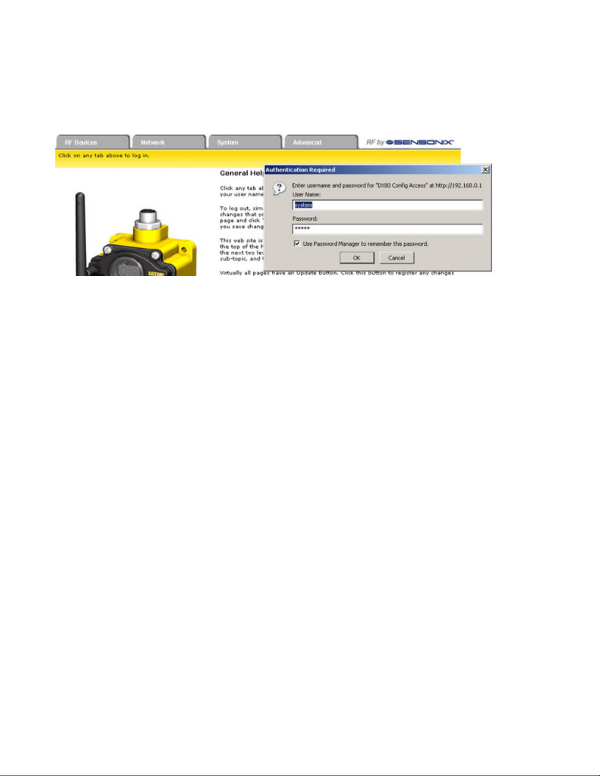
After entering the IP address, the home web page for the SureCross device displays. To log in, click on any tab at the top of the page. To
log out, close the browser.
For user-level access, enter the following as the user name and password.
• User name: system
• Password: admin
For Admin-level access, enter the following as the user name and password:
• User name: root
• Password: sxi
Admin-level access allows administrators to set up system users and their passwords. Admin-level access is also required to change the
IP address of the system.
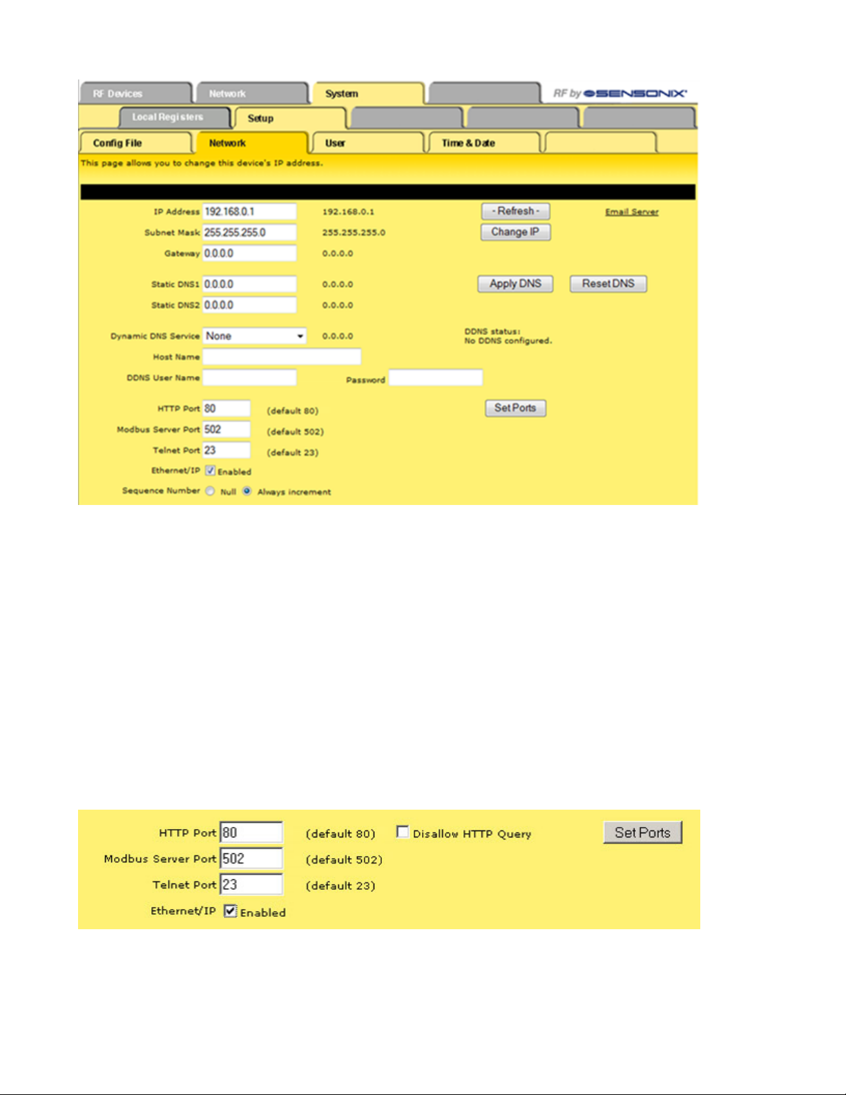
Changing the Device's IP Address
Once logged into the system, use the page tabs at the top of the page to select the path: System > Setup > Network. To change the
Ethernet Bridge or GatewayPro’s IP address:
1. Type in the new IP address
2. Click the Change IP button.
3. Cycle power to the device. The IP address change activates when the device reboots.
4 www.bannerengineering.com - tel: 763-544-3164 rev. -
Page 5
SureCross Web Configurator
IMPORTANT! Verify the new IP address is correct before cycling power to the device. After the IP address changes, you must use the
new IP address to access these configuration screens. Print this page and file for your records.
Selecting a Host Communication Protocol
By default the Ethernet Bridge and GatewayPro systems communicate with a host using Modbus/TCP. After establishing the IP address
of the Ethernet Bridge and host, the system is set up to use Modbus/TCP.
The system can also use EtherNet/IP™. To change the system to EtherNet/IP, follow the previous instructions regarding the device and
host IP address, and then:
1. Log in using the following user name and password. User name: root Password: sxi
2. At the bottom of the System > Setup > Network page is a checkbox to enable EtherNet/IP. Only select this box if the GatewayPro
system is running on an EtherNet/IP network. This change cannot be enabled from a login other than the “root” login.
3. After selecting the EtherNet/IP Enabled checkbox, click the Set Ports button to save any changes made to the HTTP Port, Modbus
Server Port, Telnet Port, or EtherNet/IP Enabled settings.
4. Cycle power to the Ethernet Bridge or GatewayPro to complete this update. After the device powers up, the changes should be
registered.
Get ALL
For an existing network, perform a Get ALL for the devices and save the XML file before changing any network parameters. The default
XML file stored on the Ethernet Bridge or GatewayPro may not accurately represent your configured network.
rev. - www.bannerengineering.com - tel: 763-544-3164 5
Page 6

The Get ALL command retrieves the parameters on the Configure Points and I/O Linking pages. These parameters are specific to the
wireless network. The Get ALL command does not retrieve parameters involving the host system or the wired network components.
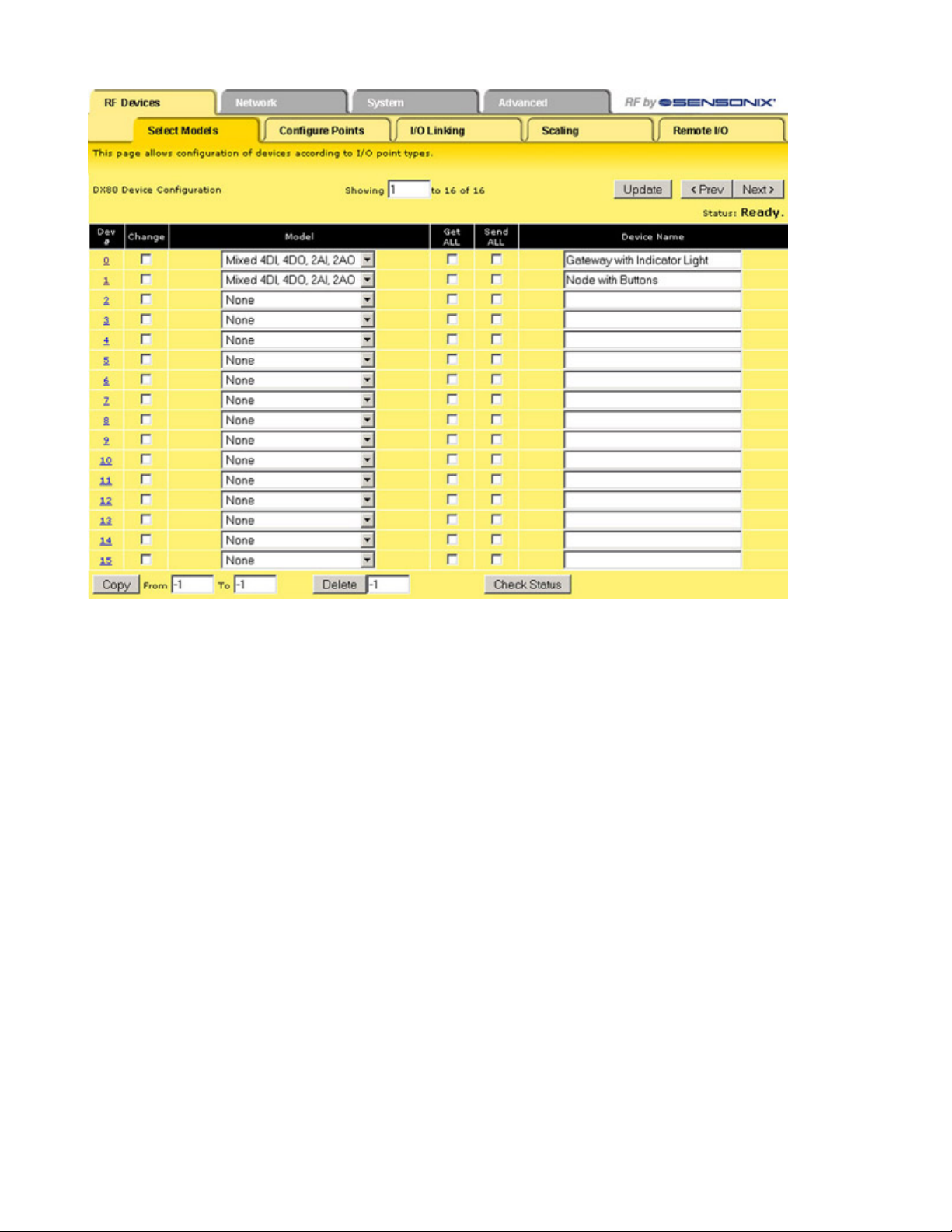
1. From the RF Devices > Select Models screen, verify the DX80 radio devices are defined using the Models drop-down list and the
device name. If you make any changes to this list, select the Change box, then click the Update button to send the new device list
to the GatewayPro.
2. Select the Get ALL checkbox for each radio device in the wireless network.
3. Click the Update button to retrieve configuration information from each DX80 device.
4. The Get ALL command will take a few minutes to complete. Click on the Check Status button to review the status of the command.
When all devices are "Ready," the command has finished.
SureCross Web Configurator
Saving Changes to the XML File
To permanently save the changes to the XML file, go to the System > Setup > Config File page and click the Save button. Changes made
by clicking an Update button are temporary and only submitted to the Ethernet Bridge or GatewayPro, not the XML file.
Change, Refresh, Send, and Update Commands
Buttons commonly appearing on most configuration screens are the Change, Refresh, Send, and Update buttons. Each of these buttons
performs a slightly different task.
Change If you leave any Web Configurator screen with-
out clicking the Change button to submit the
changes to the Ethernet Bridge or GatewayPro,
all changes are lost.
Refresh Click the Refresh button to refresh the screen
image. This updates any information on the
screen that may have changed on the device.
Send Clicking the Send button transmits device and I/O
parameters to the radio devices. The Send operation usually requires several second to complete.
Update
Clicking the Update button sends information to
the Ethernet Bridge or GatewayPro or retrieves information depending on which checkboxes are selected: Change or Get/Send All. Updating information does not save configuration information permanently to the XML file.
RF Devices Tab
Use the RF Devices tab to configure the radio network devices and I/O points.
Select Models
The Select Models tab displays the list of devices for the radio network. Use this screen to define the wireless network devices.
6 www.bannerengineering.com - tel: 763-544-3164 rev. -
Page 7
SureCross Web Configurator
Defining a Device
To define the DX80 radio network devices:
1. Select the device from the drop-down list, always using device zero for the Gateway. Most device descriptions can apply to either
the Gateway or the Node.
2. Name the device.
3. Select the Change checkbox.
4. Click the Update button to send this information to the Ethernet Bridge.
Using the Change checkbox and Update buttons sends the only device name and model to the Ethernet Bridge/GatewayPro device. This
will not overwrite existing I/O parameter information.
After the devices are defined and named, retrieve any existing parameter configuration information from the DX80 devices and load these
settings into the GatewayPro or Ethernet Bridge:
1. Select the Get ALL checkbox for each device.
2. Click the Update button.
The Get ALL command will take a few minutes to complete. Click on the Check Status button to review the command's status.
Copying a Defined Device
When setting up a radio network that includes devices with the same configuration, set up one device and copy it using the Copy button
at the bottom of the screen. Copying one device’s setup to another device also copies the Configure Points information. To copy device
parameters, fill in the From and To boxes with the appropriate device number (listed on the left side of the table) and click the Copy
button.
Submitting Parameters to the DX80 Devices
After defining the devices in the radio network, including the items from the Configure Points screen, the expanded Configure Points
screen, and the I/O Linking screen, check the Send ALL box for the devices and click the Update button on the Select Models screen.
rev. - www.bannerengineering.com - tel: 763-544-3164 7
Page 8

This sends the I/O point configuration information to the DX80 devices. Once the Send ALL function has begun, click the Check Status
button at the bottom of the screen. A monitoring screen displays each device’s progress.
SureCross Web Configurator
Other Commands
Check
Status
Get
ALL
Prev
and
Next
Click the Check Status button to watch the status of a Get ALL or Send ALL command. Sending or retrieving information from the DX80 devices can take several minutes. Use the Check
Status button to verify the error status of the data transfer. When the list reads "Ready," the
command has finished.
Select the Get ALL checkbox and click the Update button to pull set-up parameters from the
DX80 devices. These parameters will be loaded
into the Web Configurator screens but will not be
automatically saved into the XML file. Before
modifying any existing radio network devices, always perform a Get ALL to update the Web
Configurator with accurate set-up information.
If there are more than 16 devices or rules/maps,
use the Prev and Next buttons to display the
next screen of information.
Send
All
Update
After defining and setting up the devices and I/O
point parameters, select the Send ALL checkbox
and click the Update button to send this information to the radio network devices.
Clicking the Update button sends information to
the Ethernet Bridge or GatewayPro or retrieves information depending on which checkboxes are
selected: Change or Get/Send All. Updating information does not save configuration information
permanently to the XML file.
Saving Changes to the XML File
To permanently save the changes to the XML file, go to the System > Setup > Config File page and click the Save button. Changes made
by clicking an Update button are temporary and only submitted to the Ethernet Bridge or GatewayPro, not the XML file.
Model List
Select from one of the following models to define your device.
None. No device is present
Discrete 4DI, 4DO. Discrete device with four discrete in and four discrete out.
Discrete 6DI, 6DO. Discrete device with six discrete in and six discrete out.
Discrete 8DI, 4DO. Discrete device with eight discrete in and four discrete out.
Discrete 4DI, 8DO. Discrete device with four discrete in and eight discrete out.
Mixed 2DI, 2DO, 2AI, 2AO. Device with two discrete in, two discrete out, two analog in, and two analog out. The term “mixed” refers to a
device with both discrete and analog I/O.
Mixed 4DI, 4DO, 2AI, 2AO. Device with four discrete in, four discrete out, two analog in, and two analog out.
Analog 4AI, 4AO. Device with four analog in and four analog out.
Flex 2DI, 2DO, 2AI. FlexPower™ Node with two discrete in, two discrete out, and two analog in.
Flex 2DI, 2DO, 4AI. FlexPower Node with two discrete in, two discrete out, and four analog in. This description also includes the Thermo-
couple and RTD nodes.
M-GAGE. FlexPower M-GAGE™ Node.
Other. Other model that isn't currently defined.
8 www.bannerengineering.com - tel: 763-544-3164 rev. -
Page 9
SureCross Web Configurator
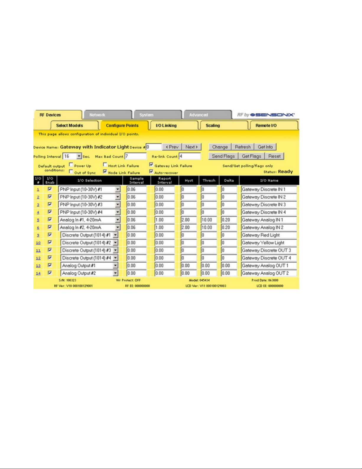
Configure Points
After setting up the basic model for each device, configure the I/O points. There are two ways to access the I/O points configuration
screen:
1. Use the Configure Points tab; or
2. Click on the hyperlinked device number in the left column of the Select Models table to access the Expanded Configure Points
page (see the Expanded Configure Points section).
Refer to the device’s data sheet for factory default information.
Note: If you leave any Web Configurator screen without clicking the Change button to submit the changes to the Ethernet Bridge or
GatewayPro, all changes are lost.
Setting Up I/O Points
To set up an I/O point:
1. Select the I/O Enabled checkbox. Any active I/O point must be enabled or the I/O is ignored.
2. Select an I/O type from the I/O Selection drop-down list.
3. The Configure Points sample screen shows a Gateway defined with four discrete IN, four discrete OUT, two analog IN, and two
analog OUT points. Always refer to the device data sheet to determine which discrete and which analog I/O points are active for a
given device. Note, however, that the NPN and PNP settings for discrete I/O shown on the data sheet are only default configuration
settings and can be changed.
4. Define any applicable parameters, e.g. sample interval, report interval, hysteresis, threshold, or any other parameter displaying on
the main or expanded view screens.
5. After setting up all I/O points using either the Configure Points tab or the expanded Configure Points screen, click the Change
button to submit the changes to the Ethernet Bridge or GatewayPro.
6. To send all I/O data to the devices, use the Select Models screen by selecting the Send ALL checkbox and clicking the Update
button. To send the individual I/O point changes, use the expanded Configure Points screen and the Send button.
rev. - www.bannerengineering.com - tel: 763-544-3164 9
Page 10

I/O Status
SureCross Web Configurator
Parameters
The following parameters are set on the Configure Points screen.
Change If you leave any Web Configurator screen with-
out clicking the Change button to submit the
changes to the Ethernet Bridge or GatewayPro, all changes are lost.
Delta The delta parameter defines the change re-
quired between sample points of an analog input before the analog input reports a new value. To turn off this option, set the Delta value
to 0.
Default
Output
Condition
Flags
The default output conditions are a set of
checkboxes to establish device-based parameters and apply to all outputs on this device. After making changes to the flags, click the Send
Flags button to submit the changes to the device.
Auto-Recover. Selecting the Auto-Recover
option forces the Gateway to attempt to re-establish communications with out-of-sync nodes
after a polling error condition is indicated. The
Gateway polls the failing device and must successfully communicate with the failing node
Re-Link Count times before the error condition
is erased. This parameter is only used on the
Gateway. Without the auto-recover feature selected, the user must manually reset error conditions or the host system must reset the error
condition.
Gateway Link Failure. The Gateway detected
a communication problem with a Node. All
linked outputs of the failing device are set to
the default states.
Prev
and
Next
Refresh
If there are more than 16 devices or rules/maps,
use the Prev and Next buttons to display the next
screen of information.
Click the Refresh button to refresh the screen image. This updates any information on the screen
that may have changed on the device.
Report
Interval/
Rate
The report rate defines how often the Node communicates the I/O status to the Gateway. Change
of state reporting sets the system to report only
when the value crosses the threshold setting. For
FlexPower™ applications, setting the report rate
to a slower rate extends the battery life.
Relink
Count
The re-link count is the number of completed polling messages the Gateway receives from a Node
before a lost RF link is considered re-established
and normal operation resumes.
Reset The Reset button resets any error conditions dis-
played. Until the error message is reset, the device will not start any additional operations.
Sample Interval/
Rate
The sample interval, or rate, defines how often
the SureCross device samples the input. For battery-powered applications, setting a slower rate
extends the battery life.
Host Link Failure. A Modbus timeout forces
all device outputs to the default states. This
parameter applies to every device that sets
this flag.
Node Link Failure. A Node detected an RF
link problem and set its own outputs to the default states.
Out of Sync. When an out-of-sync condition is
detected, all Node outputs are set to the default value. This parameter applies only to the
Nodes.
Power Up. All device outputs are set to the default value on initial power-up.
Get Info The Get Info button retrieves factory informa-
tion for the selected device, such as the model
10 www.bannerengineering.com - tel: 763-544-3164 rev. -
number, serial number, and production date.
Page 11
Are you there?
Yes, I am here.
Threshold
ON point
Time
Input Value
Input
Hysteresis
OFF point
SureCross Web Configurator
I/O Enable
Select the checkbox to enable the individual I/
O point. If the checkbox is not selected, that I/
O point is disabled, regardless of what other
parameters may be defined. For efficient power usage, do not enable I/O points that are not
used.
I/O Name The I/O name field is an optional text field used
to assign names to the individual I/O points for
easy reference. This name may appear in
many other screens relating to the I/O point.
I/O
Number
Click on the I/O # hyperlink on the far left of the
screen to access an additional screen for I/O point
configuration. The expanded screen contains
more I/O point parameters than is displayed on
the primary page.
I/O
Selection or
Type
Select the I/O type from the drop-down list. The
drop-down list includes all options available for the
entire DX80 line. Not all I/O types included in the
drop-down list are applicable for any given device.
Refer to the device data sheet to determine which
options are available for each device.
“Other” Type #: Occasionally some newly designed and released devices will use I/O types not
yet listed in the drop-down list for I/O Type. When
this happens, Banner Engineering applications
engineers will supply the “other” type number. Select Other from the I/O Type drop-down list and
enter the I/O type number supplied by Banner Engineering into this field.
Send
Flags,
Get
Flags
Threshold and
Hysteresis
The Send Flags and Get Flags buttons refer only to the Default Output Conditions flags, not the
I/O parameters.
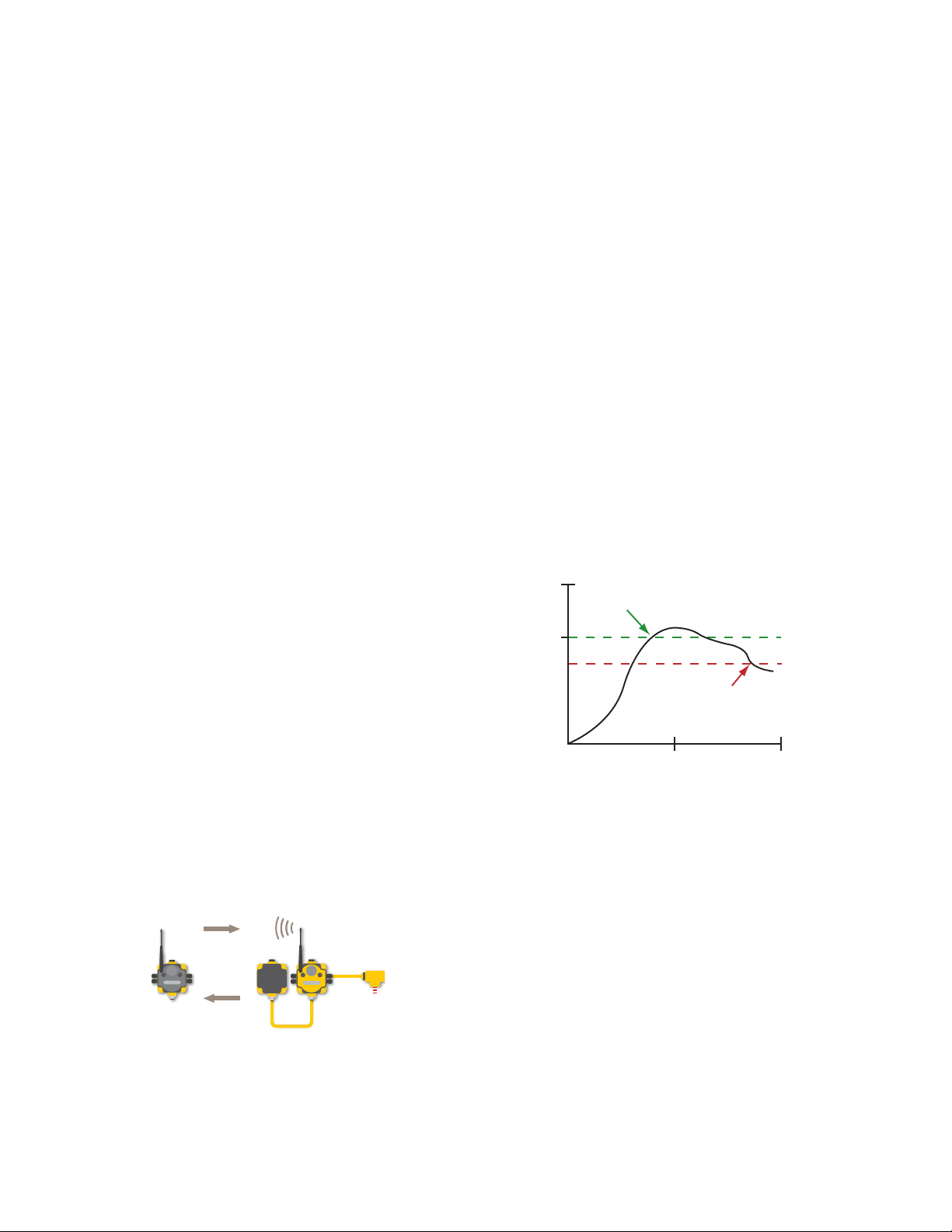
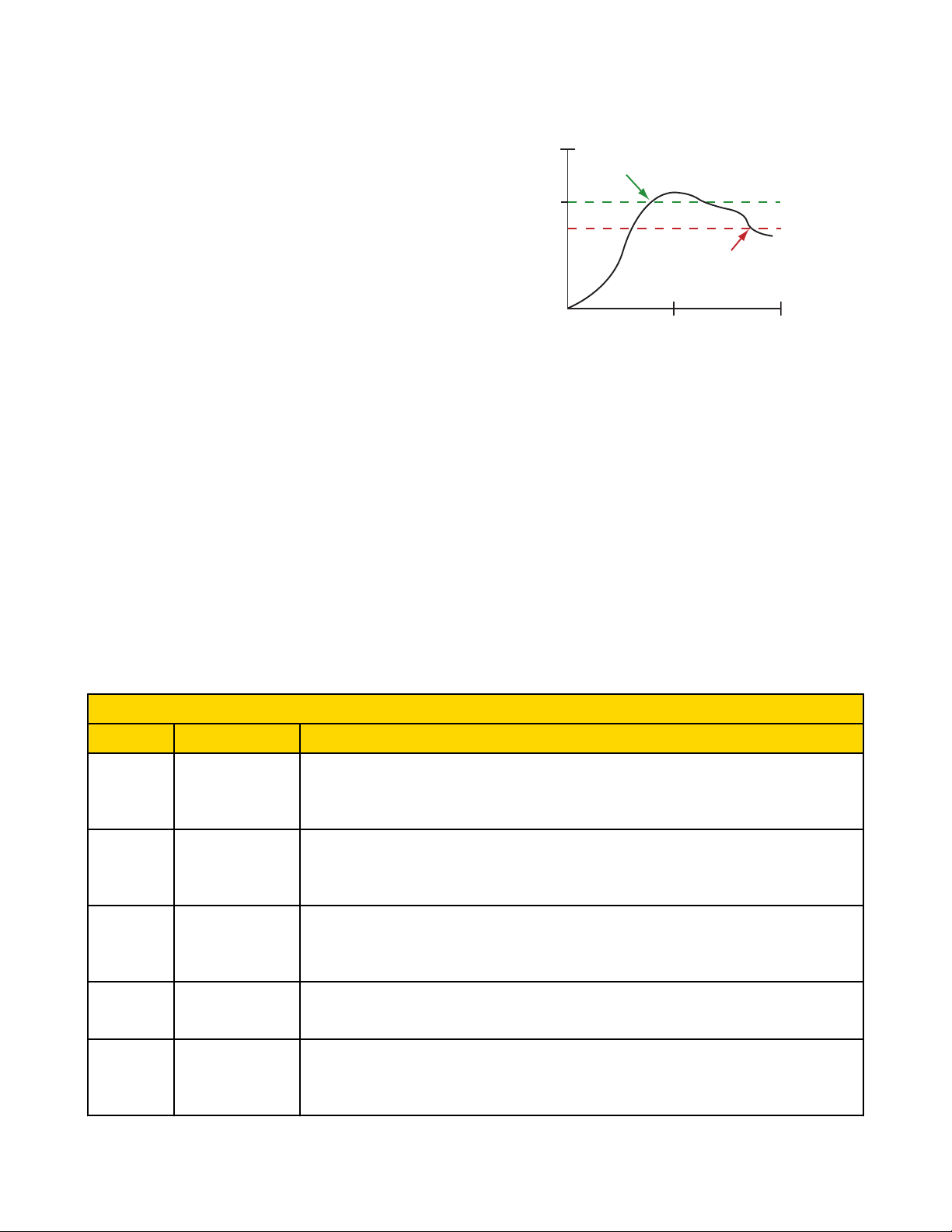
Threshold and hysteresis work together to establish the ON and OFF points of an analog input. The threshold defines a trigger point or reporting threshold (ON point) for a sensor input.
The hysteresis value establishes how much below the active threshold (ON point) an analog input is required to be before the input is considered OFF. A typical hysteresis value is 10% to
20% of the unit’s range.
Maximum
Bad
Count
Polling Interval/
Rate
The max bad count refers to a user-established
maximum count of consecutive failed polling attempts before the Gateway considers the RF link
to have failed.
To monitor network health, the Gateway communicates with, or polls, each Node to determine if
the radio link is active. The polling rate defines
how often the Gateway communicates with each
Node. Polling is always initiated by the Gateway
and only verifies radio signal communications.
Expanded Configure Points
Most I/O point parameters are changed using the expanded view of the Configure Points tab.
rev. - www.bannerengineering.com - tel: 763-544-3164 11
In the example shown graphically, the input is
considered on at 15 mA. To consider the input
off at 13 mA, set the hysteresis to 2 mA. The input will be considered off when the value is 2
mA less than the threshold.
Page 12
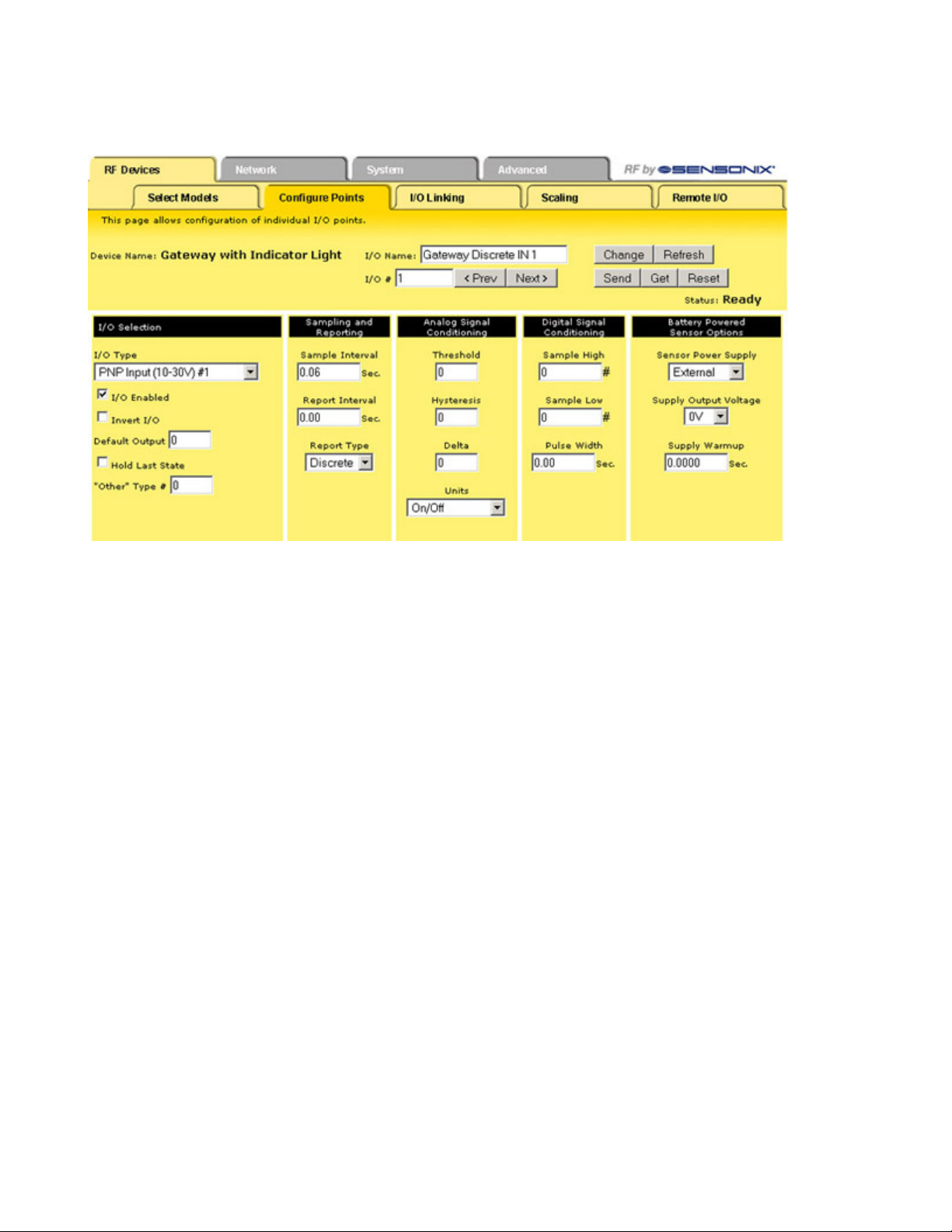
SureCross Web Configurator
To access this expanded view, which displays all parameters for the I/O point selected, click on the I/O number hyperlink from the Configure Points tab. Several parameters on the expanded view also appear in the standard Configure Points screen and can be modified from
either screen.
After making changes to the parameters screen:
1. Click the Change button to submit the changes to the Ethernet Bridge or GatewayPro.
2. Click the Send button to update the radio devices.
Change If you leave any Web Configurator screen
without clicking the Change button to submit
the changes to the Ethernet Bridge or GatewayPro, all changes are lost.
Get Click the Get button to read all device and I/O
parameters from the DX80 device and load
them into the Web Configurator screens. This
does not save the parameters to the XML file.
Prev and
Next
If there are more than 16 devices or rules/
maps, use the Prev and Next buttons to display the next screen of information.
Refresh Click the Refresh button to refresh the screen
image. This updates any information on the
screen that may have changed on the device.
Reset The Reset button resets any error conditions
displayed. Until the error message is reset,
the device will not start any additional operations.
Saving
Changes to
the XML
File
To permanently save the changes to the
XML file, go to the System > Setup > Config
File page and click the Save button.
Changes made by clicking an Update button
are temporary and only submitted to the
Ethernet Bridge or GatewayPro, not the XML
file.
Send Clicking the Send button transmits device
and I/O parameters to the radio devices. The
Send operation usually requires several second to complete.
I/O Selection
Default
Output
Value
Default output values are specific values written to output registers. For discrete outputs,
this is a 1 (on) or 0 (off) value. For analog outputs the value can be any valid register value.
I/O Enable
Select the checkbox to enable the individual I/O
point. If the checkbox is not selected, that I/O
point is disabled, regardless of what other parameters may be defined. For efficient power usage,
do not enable I/O points that are not used.
12 www.bannerengineering.com - tel: 763-544-3164 rev. -
Page 13
I/O Status
SureCross Web Configurator
When a default condition occurs, these default
output values are written to the output register.
Hold
Last
State
The I/O point retains the last value recorded instead of the default output value during selected default conditions.
Invert I/O Selecting this checkbox inverts the digital rep-
resentation of the I/O.
Sampling and Reporting
Report
Interval/
Rate
The report rate defines how often the Node communicates the I/O status to the Gateway. Change
of state reporting sets the system to report only
when the value crosses the threshold setting. For
FlexPower™ applications, setting the report rate to
a slower rate extends the battery life.
I/O Selection
or
Type
Sample
Interval/
Rate
Select the I/O type from the drop-down list. The
drop-down list includes all options available for
the entire DX80 line. Not all I/O types included in
the drop-down list are applicable for any given device. Refer to the device data sheet to determine
which options are available for each device.
“Other” Type #: Occasionally some newly designed and released devices will use I/O types
not yet listed in the drop-down list for I/O Type.
When this happens, Banner Engineering applications engineers will supply the “other” type number. Select Other from the I/O Type drop-down list
and enter the I/O type number supplied by Banner Engineering into this field.
The sample interval, or rate, defines how often the
SureCross device samples the input. For batterypowered applications, setting a slower rate extends the battery life.
Report
Type
Select from discrete or analog format reporting
types. Analog data requires sixteen bits while discrete data uses only one bit per I/O point. Selecting
double from the list uses two consecutive registers,
each consisting of sixteen bits.
Analog Signal Conditioning
Delta The delta parameter defines the change required be-
tween sample points of an analog input before the
analog input reports a new value. To turn off this option, set the Delta value to 0.
Digitial Signal Conditioning
Sample
High/
Sample
Low
(Dis-
For discrete inputs, the sample high parameter
defines the number of consecutive samples the
input signal must be high before a signal is considered active. Sample low defines the number
of consecutive samples the input signal must be
low before a signal is considered low. The sam-
Threshold and
Hysteresis
Threshold and hysteresis work together to establish the ON and OFF points of an analog input. The threshold defines a trigger point or reporting threshold (ON point) for a sensor input.
The hysteresis value establishes how much below the active threshold (ON point) an analog input is required to be before the input is consid-
rev. - www.bannerengineering.com - tel: 763-544-3164 13
Page 14
Threshold
ON point
Time
Input Value
Input
Hysteresis
OFF point
SureCross Web Configurator
crete I/O)ple high and sample low parameters are used
to create a filter to avoid unwanted input transi-
ered OFF. A typical hysteresis value is 10% to
20% of the unit’s range.
tions. The default value is 0, which disables this
feature. The value range is 1 through 255.
Pulse
Width
The pulse width determines the length of time,
in seconds, that a digital output is active (1) before returning to zero. Select 0 to disable this
feature.
In the example shown graphically, the input is
considered on at 15 mA. To consider the input
off at 13 mA, set the hysteresis to 2 mA. The in-
put will be considered off when the value is 2
mA less than the threshold.
Units Defined
The units parameter defines the range and/or type of data value associated with an input or output.
Selecting Units from within any configuration tool changes the units definition of several parameters, including threshold, hysteresis, and
delta. For example, if the units are 0-20 mA, the threshold, hysteresis, and delta values are entered as milliampere values. Selecting
Temp C changes the threshold, hysteresis, and delta units to degrees Celsius.
Signed values range from −32768 to +32767 and allow for the measurement of negative values. Signed values are typically used for
measuring temperatures. Signed values are stored as two's complement values.
Unsigned values range from 0 to 65535 and are used to measure values that do not go below zero, such as 4 to 20 mA, distance, or a
counter.
Input Units
Units Description Definition
0 Raw Displays the raw A/D conversion data with data ranges from 0 to 65535. This units type is typical-
ly used only for factory calibration.
LCD: Raw A/D hex value
1 4 to 20 mA Analog unit. Modbus register contents are scaled such that 0 represents 4 mA and 65535 repre-
sents 20 mA.
LCD: 4.00mA–20.00mA
2 0 to 20 mA Default analog input unit. Modbus register contents are scaled such that 0 represents 0 mA and
65535 represents 20 mA.
LCD: 0.00mA–20.00mA
3 Discrete (ON/OFF) Default discrete input unit.
LCD: ON/OFF
4 0 to 10V (Volts) Analog input using 0 to 10V instead of current. Modbus register contents are scaled such that 0
14 www.bannerengineering.com - tel: 763-544-3164 rev. -
represents 0V and 65535 represents 10V.
LCD: 0.00V–10.00V
Page 15

SureCross Web Configurator
Input Units
Units Description Definition
6 Temp °C Celsius, high resolution. Analog input for temperature devices such as thermocouples, RTD, and
thermistors. In high resolution mode, temperature = (Modbus register value) ÷ 20.
LCD: 0000.0C
7 Temp °F Fahrenheit, high resolution. Analog input for temperature devices such as thermocouples, RTD,
and thermistors. In high resolution mode, temperature = (Modbus register value) ÷ 20.
LCD: 0000.0F
8 Temp °C (Low Res) Celsuis, low resolution. To measure a greater temperature range, use the low resolution unit. In
low resolution mode, temperature = (Modbus register value) ÷ 2.
LCD: 0000.0C
9 Temp °F (Low Res) Fahrenheit, low resolution. To measure a greater temperature range, use the low resolution unit.
In low resolution mode, temperature = (Modbus register value) ÷ 2.
LCD: 0000.0F
10 Asynchronous
Counter, 32-bit
11 Asynchronous
Counter, 16-bit
The 32-bit counter value records counts up to 4.29 billion.
LCD: 0000 0000
The 16-bit counter value records counts up to 65535.
LCD: 0000
Output Units
Units Description Definition
0 Raw Displays the raw A/D conversion data with data ranges from 0 to 65535. This units type is typical-
ly used only for factory calibration.
LCD: Raw A/D hex value
1 4 to 20 mA Analog unit. Modbus register contents are scaled such that 0 represents 4 mA and 65535 repre-
sents 20 mA.
LCD: 4.00mA–20.00mA
2 0 to 20 mA Default analog input unit. Modbus register contents are scaled such that 0 represents 0 mA and
65535 represents 20 mA.
LCD: 0.00mA–20.00mA
3 Discrete (ON/OFF) Default discrete unit.
LCD: ON/OFF
4 0 to 10V (Volts) Analog unit using 0 to 10V instead of current. Modbus register contents are scaled such that 0
represents 0V and 65535 represents 10V.
LCD: 0.00V–10.00V
5 Signed Analog, 0 to
10V
For a signed value, such as temperature, that is to be converted to a voltage out value. Use null
to set the start point and span to define the range. The null value is the starting temperature to be
associated with 0V. The span is the entire temperature range that is to be associated with 0 to
10V.
LCD: 0.00V–10.00V
rev. - www.bannerengineering.com - tel: 763-544-3164 15
Page 16

SureCross Web Configurator
Units Description Definition
Output Units
6 Signed Analog, 0 to
20 mA
7 Unsigned Analog, 0
to 20 mA
8 Signed Analog, 4 to
20 mA (A)
9 Signed Analog, 4 to
20 mA (B)
10 Unsigned Analog, 0
to 10V
For a signed value, such as temperature, that is to be converted to a mA out value. Use null to
set the start point and span to define the range. The null value is the starting temperature to be
associated with 0 mA. The span is the entire temperature range that is to be associated with 0 to
20 mA.
LCD: 0.00mA–20.00mA
For unsigned values, such as a counter, that is to be converted to a mA out value. Use the null to
set the start point and span to define the range. The null value is the distance to be associated
with 0 mA. The span is the entire distance range that is to be associated with 0 to 20 mA.
LCD: 0.00mA–20.00mA
In older models, this units type is for degree Celsius conversions only. Use null to set the start
point and span to define the range. The null value is the starting temperature to be associated
with 4 mA. The span is the entire temperature range that is to be associated with 4 to 20 mA. For
newer firmware models, type codes 8 and 9 are treated the same.
LCD: 4.00mA–20.00mA
In older models, this units type is for degree Fahrenheit conversions only. Use null to set the start
point and span to define the range. The null value is the starting temperature to be associated
with 4 mA. The span is the entire temperature range that is to be associated with 4 to 20 mA. For
newer firmware models, type codes 8 and 9 are treated the same.
LCD: 4.00mA–20.00mA
For an unsigned value, such as 0 to 20 mA, that is to be converted to a voltage out value. Use the
null to set the start point and span to define the range. The null value is the distance to be associated with 0V. The span is the entire distance range that is to be associated with 0 to 10V.
LCD: 0.00V–10.00V
11 Counter, 16-bit The 16-bit counter value records counts up to 65535.
LCD: 0000
12 Unsigned Analog, 4
to 20 mA
For an unsigned value, such as 0 to 10V, that is to be converted to a mA out value. Use the null
to set the start point and span to define the range. The null value is the distance to be associated
with 4 mA. The span is the entire distance range that is to be associated with 4 to 20 mA.
LCD: 4.00mA–20.00mA
Battery Powered Sensor Options
Sensor Power Supply
Select a power supply for the sensor device. Select Supply 1 through 4 to indicate the external device is powered from one of the Node’s
supplied switch power connectors.
External. The sensor is powered from outside the Node.
Supply #1. Switched power 1 (SP1)
Supply #2. Switched power 2 (SP2)
Supply #3. Switched power 3 (SP3)
Supply #4. Switched power 4 (SP4)
16 www.bannerengineering.com - tel: 763-544-3164 rev. -
Page 17
Warmup Time
0 Volts
Switch Power
Sample point
Sample point
Sample interval
Voltage
SureCross Web Configurator
Supply Output Voltage
The Supply Output Voltage sets the voltage required for the sensor device. This parameter is only applicable when using the supplied
switch power option.
Supply Warmup
Supply Warmup defines the length of time the switch power should be turned on before examining the sensor’s input.
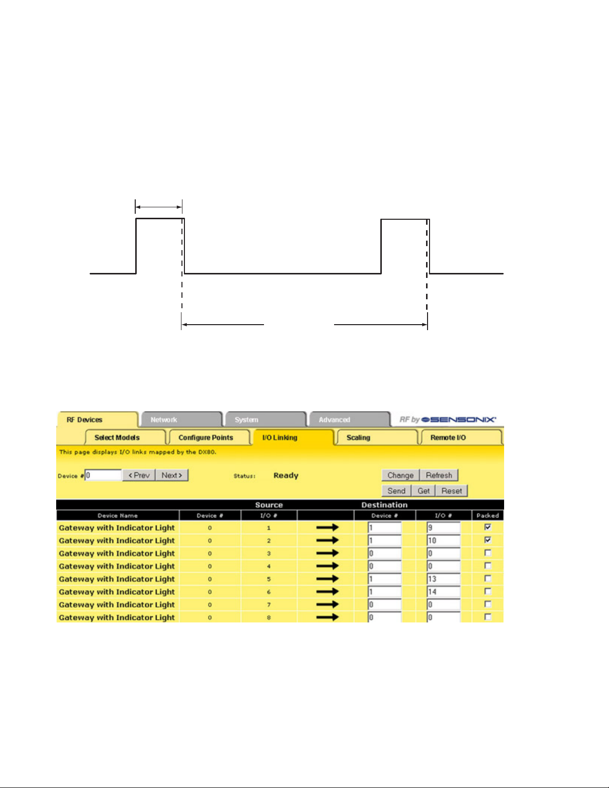
I/O Linking
Each device input point can be linked or connected to any output point in the system. An output link defined as zero for the device and
zero for the output point is not connected. Valid output points on all devices are nine through fourteen; valid devices are one through
fifteen with zero reserved for the Gateway (or GatewayPro).
In the sample screen shown, the Gateway input points can be mapped to any Node’s outputs. Manually enter the device number in the
Destination Device # box, then enter the I/O point number for that destination device.
After making changes to this screen:
1. Click on the Change button to send the changes to the DX83 Ethernet Bridge or the GatewayPro
2. Click on the Send button to send these changes to the device.
rev. - www.bannerengineering.com - tel: 763-544-3164 17
Page 18

SureCross Web Configurator
Change If you leave any Web Configurator screen with-
out clicking the Change button to submit the
changes to the Ethernet Bridge or GatewayPro,
all changes are lost.
Get Click the Get button to read all device and I/O
parameters from the DX80 device and load
them into the Web Configurator screens. This
does not save the parameters to the XML file.
Packed
Flag
Setting the Packed flag communicates discrete
output point information more efficiently. Instead
of sending one message for each output
change, discrete values are packed into one
message sent to the destination device. The
packing data reduces the wireless device traffic
and improves the timing in critical applications
when multiple inputs from a single device are
connected to outputs on one other device.
The Packed flag only affects the output point
messages, the input message communication is
defined by each device I/O point. If a device I/O
point Report Type parameter is defined as discrete, the input reporting messages for this
point are packed into one wireless message.
For greatest efficiency, all discrete inputs
should be defined as a discrete Report Type.
Refresh Click the Refresh button to refresh the
screen image. This updates any information
on the screen that may have changed on the
device.
Reset The Reset button resets any error conditions
displayed. Until the error message is reset,
the device will not start any additional operations.
Saving
Changes to
the XML
File
To permanently save the changes to the
XML file, go to the System > Setup > Config
File page and click the Save button.
Changes made by clicking an Update button
are temporary and only submitted to the
Ethernet Bridge or GatewayPro, not the XML
file.
Send Clicking the Send button transmits device
and I/O parameters to the radio devices. The
Send operation usually requires several second to complete.
Prev
and
Next
If there are more than 16 devices or rules/maps,
use the Prev and Next buttons to display the
next screen of information.
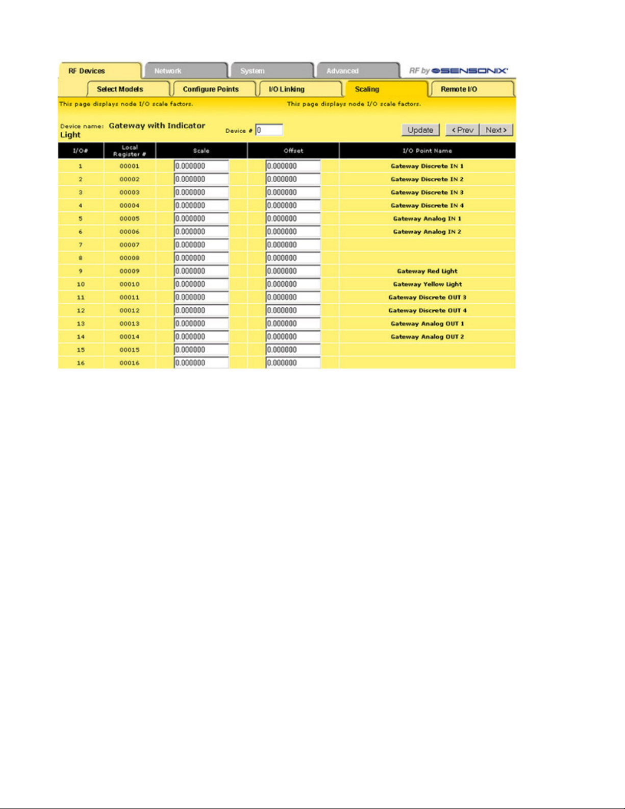
Scaling
The Scaling screen is used for converting data.
Raw data is multiplied by the Scale and added to the Offset to produce the data appearing in the floating point register associated with
the I/O point. The floating point registers start at register 1001.
18 www.bannerengineering.com - tel: 763-544-3164 rev. -
Page 19
SureCross Web Configurator
For example, thermocouple inputs are multiplied by 20 before being written to the Modbus register. To convert this register value back to
a temperature reading use the Scaling screen.
The Offset value can be used to account for errors introduced into the sensor system, such as errors introduced because of wiring
lengths in a thermocouple input system.
Other Commands
Prev and
Next
If there are more than 16 devices or rules/
maps, use the Prev and Next buttons to display
the next screen of information.
Update
Clicking the Update button sends information to the
Ethernet Bridge or GatewayPro or retrieves information depending on which checkboxes are selected: Change or Get/Send All. Updating information
does not save configuration information permanently to the XML file.
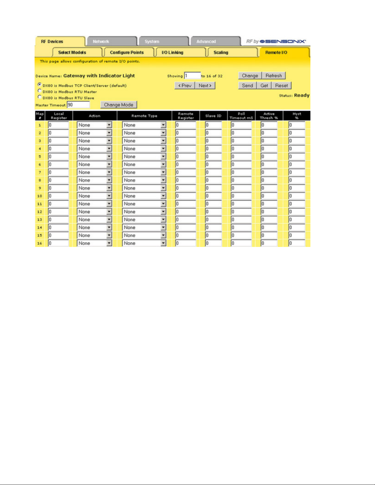
Remote I/O
The Remote I/O configuration page defines up to 32 external communication registers when the DX80 Gateway is defined as a Modbus
RTU Master.
This table is used only when the Gateway is a Modbus RTU master and it is communicating with Modbus slave devices, typically DX85
Expanded Remote I/O devices.
rev. - www.bannerengineering.com - tel: 763-544-3164 19
Page 20
SureCross Web Configurator
After power-up, the DX80 Gateway is a slave device (to the Ethernet Bridge) for the time defined in the Master Timeout field, defined in
seconds with a 90 second minimum. During this time, the operating mode can be changed using the browser interface. To change the
mode:
1. Click one of the radio buttons to select how the DX80 Gateway functions.
• Select Modbus/TCP Client/Server mode (default) when you are connecting a DX80 to an external PLC or similar equipment.
• Select Modbus RTU Master mode if the DX80 Gateway is to be a Modbus master device communicating to other slave devices using
a Modbus RS485 serial connection. The Gateway enters master mode after the Master Timeout period has elapsed.
• Select Modbus RTU Slave if the DX80 GatewayPro or a Ethernet Bridge and Gateway pair is operating as a slave on a Modbus serial
connection.
2. Set the Master Timeout field, then click the Change Mode button. When the timeout expires, the DX80 Gateway begins to operate as
selected. The Master Timeout determines how long the DX80 Gateway waits before changing modes.
3. After making changes, click on the Change button to send the changes to the DX83 Ethernet Bridge or the GatewayPro and then click
on the Send button to send these changes to the device.
Saving Changes to the XML File
To permanently save the changes to the XML file, go to the System > Setup > Config File page and click the Save button. Changes made
by clicking an Update button are temporary and only submitted to the Ethernet Bridge or GatewayPro, not the XML file.
Other Commands
Change If you leave any Web Configurator screen with-
out clicking the Change button to submit the
Reset The Reset button resets any error conditions dis-
played. Until the error message is reset, the device
will not start any additional operations.
20 www.bannerengineering.com - tel: 763-544-3164 rev. -
Page 21

SureCross Web Configurator
changes to the Ethernet Bridge or GatewayPro,
all changes are lost.
Get Click the Get button to read all device and I/O
parameters from the DX80 device and load them
into the Web Configurator screens. This does not
save the parameters to the XML file.
Refresh Click the Refresh button to refresh the screen
image. This updates any information on the
screen that may have changed on the device.
DX80 Modes
Setting Gateway GatewayPro Ethernet
Bridge
DX80 is Modbus/
Slave Master Master Default mode. The Gateway is a Modbus slave device and the EtherTCP Client/Server
(default)
DX80 is Modbus
Master Master Ignored The Ethernet Bridge can only communicate with a slave device. In
RTU Master
Send Clicking the Send button transmits device and I/O
parameters to the radio devices. The Send operation usually requires several second to complete.
net Bridge is the master device.
this mode, any communications sent to the Bridge from the Web
Configurator is ignored. To resume communications, cycle power to
the Gateway. When power is cycled, the Ethernet Bridge begins
again as a master device until the timeout lapses.
DX80 is Modbus
RTU Slave
Slave Slave Ignored Similar to the default mode, but a device other than the Ethernet
Bridge acts as the Modbus master device. The Ethernet Bridge still
communicates with the Gateway and can read and write to registers,
but another device is the master device.
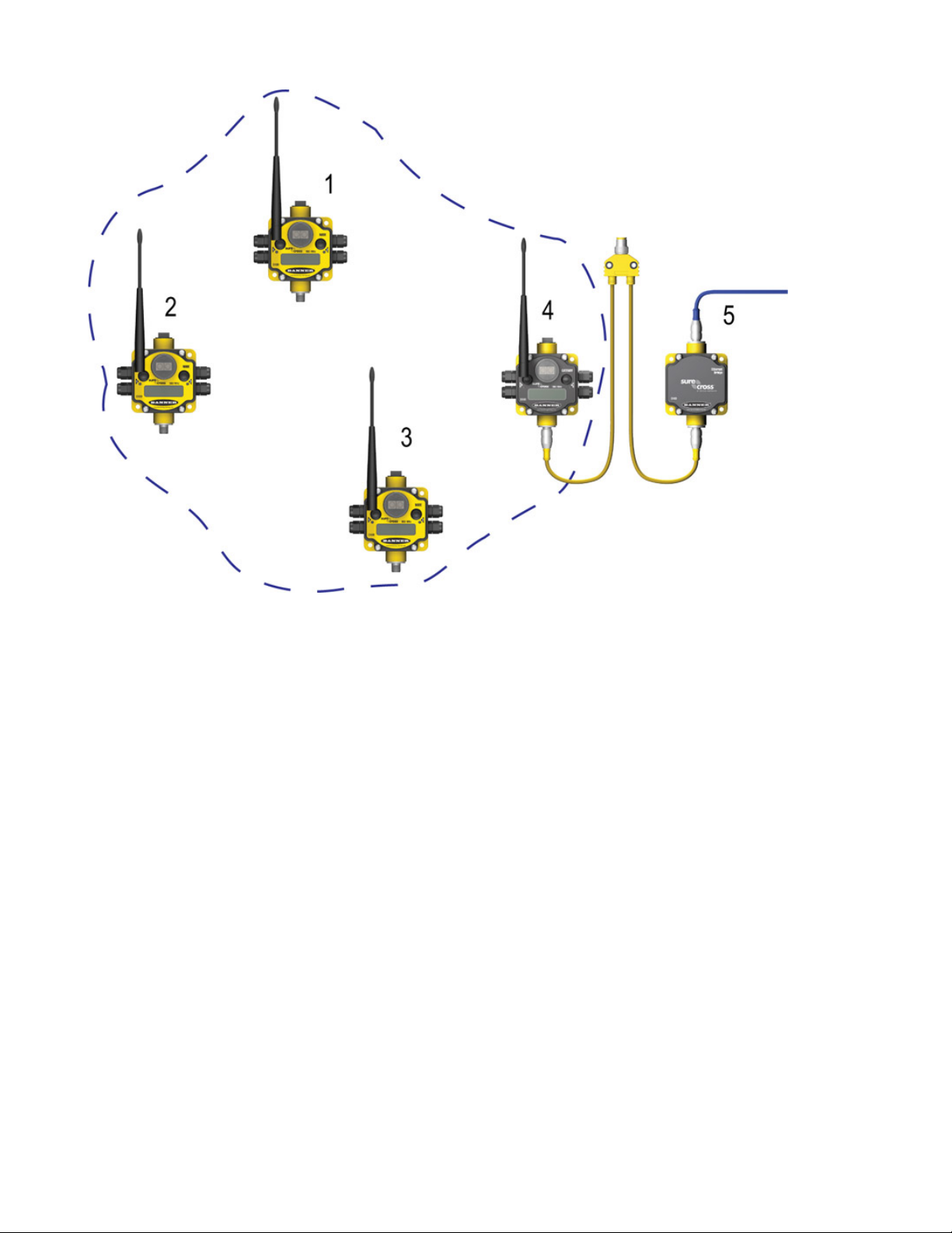
DX80 is a Modbus/TCP Client/Server (default)
The default configuration is DX80 is Modbus/TCP Client/Server. The DX83 Ethernet Bridge is the Modbus master device and only
communicates with the device configured as Slave ID 1: the Gateway.
rev. - www.bannerengineering.com - tel: 763-544-3164 21
Page 22
SureCross Web Configurator
1. Node 1, registers 17 through 32.
2. Node 2, registers 33 through 48.
3. Node 3, registers 49 through 64.
4. Gateway, Slave ID 1, registers 1 through 16.
5. DX83 Ethernet Bridge
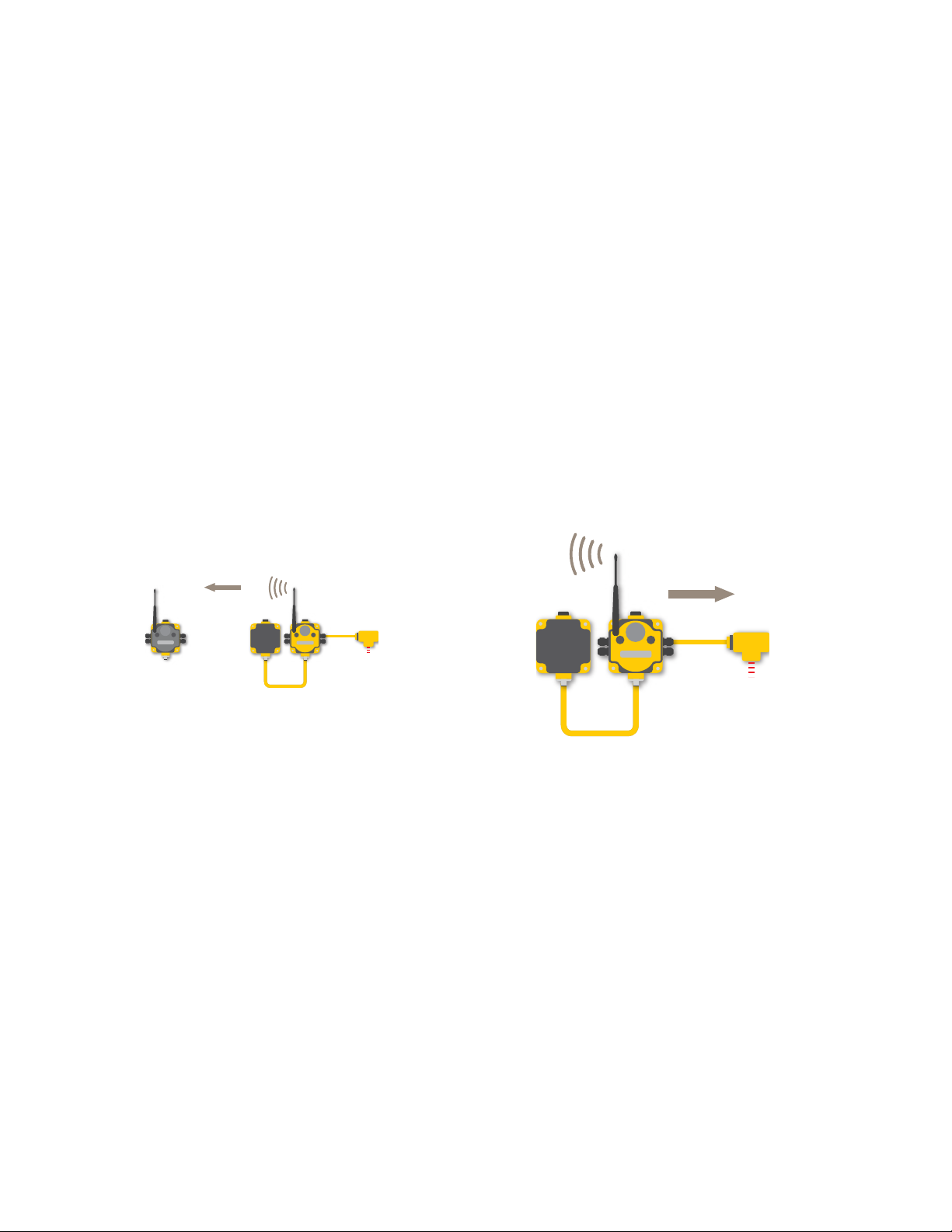
DX80 Gateway is Modbus RTU Master
When a DX80 Gateway is set up as a Modbus RTU master device, the communication between the DX83 Ethernet Bridge (used to
configure the network) and the Gateway is ignored. The Gateway acts as the Modbus RTU master device for the system, which may
include other slave Gateways or DX85 Remote I/O slave devices. All communication must go through the master device.
The master table entries define the register-to-register communication for remote I/O points. Each line represents a register/point connection between the master device and a Modbus slave device with up to 32 table entries possible. For each table entry, specify the local
Modbus register, action to perform, type of external point, external register number, external slave number, and a Modbus timeout value
for that register access. Active threshold and hysteresis are optional parameters that may be applied to registers.
After making changes:
1. Click on the Change button to send the changes to the DX83 Ethernet Bridge or the GatewayPro.
2. Click on the Send button to send these changes to the radio devices.
3. To save the changes to the XML file, go to the System > Setup > Config File page and click the Save button.
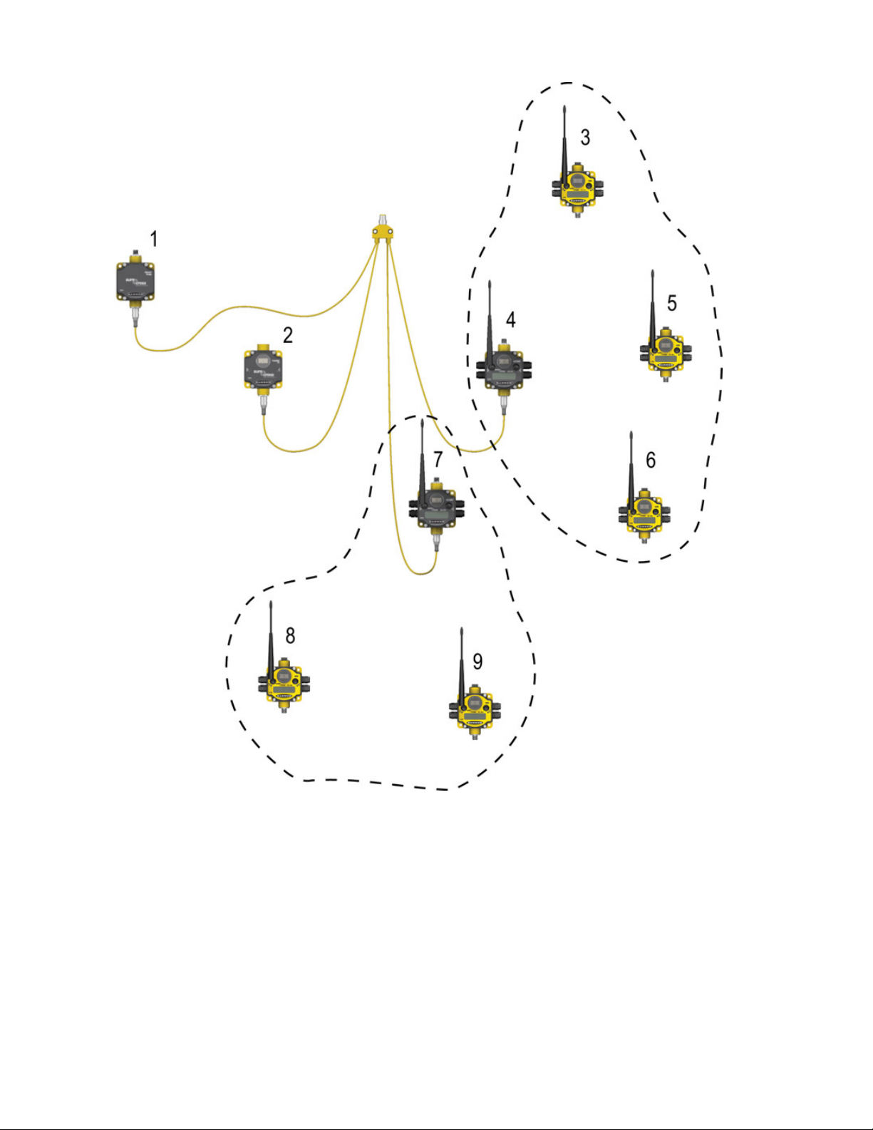
This sample network shows a DX80 Gateway as the Modbus RTU Master device. Once the Gateway is set as the master, communication is ignored between the Ethernet Bridge (normally the master) and the Gateway.
22 www.bannerengineering.com - tel: 763-544-3164 rev. -
Page 23
SureCross Web Configurator
1. DX83 Ethernet Bridge
2. Slave ID 2, DX85 Modbus RTU Remote I/O
3. Node 1, registers 17 through 32
4. Master Device, DX80 Gateway, registers 1 through 16.
5. Node 2, registers 22 through 48.
6. Node 3, registers 49 through 64.
7. Slave ID 5, DX80 Gateway, registers 1 through 16.
8. Node 2, registers 33 through 48
9. Node 1, registers 17 through 32.
rev. - www.bannerengineering.com - tel: 763-544-3164 23
Page 24

Threshold
ON point
Time
Input Value
Input
Hysteresis
OFF point
Parameters
SureCross Web Configurator
Action Select an action from the following: None, Reads
From, or Writes To. Select None to perform no
action, Reads From reads the parameter from
the remote register and copies the contents into
the local register, and Writes To writes the data
from the local register to the remote register.
Get Click the Get button to read all device and I/O
parameters from the DX80 device and load them
into the Web Configurator screens. This does not
save the parameters to the XML file.
Local
Register
Map
Number
The Local Register entry is the from register in
the I/O mapping. I/O points are linked from the
local register to the remote register.
Each map entry is defined with a map number,
one through 32. The master table entries define
the register-to-register communication for remote
I/O points. Each line represents a register/point
connection to another Modbus slave device. Up
to 32 table entries are possible.
Poll
Timeout
The poll timeout refers to the time limit, in milliseconds, to communicate with a specific slave
device. When this time limited is exceeded, the
system begins communicating with the next device in the table. The Poll Timeout setting prevents the system from stopping when a slave device is not responding.
Reset The Reset button resets any error conditions
displayed. Until the error message is reset, the
device will not start any additional operations.
SlaveIDThe slave ID is an identifying number used for
devices within a Modbus system. By default,
Gateways are set to Modbus Slave ID 1. When
using more than one Modbus slave, set each
slave to a unique ID number.
Threshold and
Hysteresis
Threshold and hysteresis work together to establish the ON and OFF points of an analog input. The threshold defines a trigger point or reporting threshold (ON point) for a sensor input.
The hysteresis value establishes how much below the active threshold (ON point) an analog input is required to be before the input is considered OFF. A typical hysteresis value is 10% to
20% of the unit’s range.
Refresh
Remote
Regis-
Click the Refresh button to refresh the screen image. This updates any information on the screen
that may have changed on the device.
The Remote Register entry is the to register in
the I/O mapping. I/O points are linked from the
local register to the remote register.
In the example shown graphically, the input is
considered on at 15 mA. To consider the input
off at 13 mA, set the hysteresis to 2 mA. The input will be considered off when the value is 2
mA less than the threshold.
ter
Remote
Type
Select a type from the following drop-down list:
none, coil (output), discrete input, input register,
or holding register. DX80 device registers are all
holding registers. Banner Engineering’s SureCross™ slave devices use only input registers
and holding registers. When using slave devices
from other manufacturers, please refer to the
manufacturer’s documentation to determine what
I/O types they use.
Coil (output). 1xxxx - Other slave devices, write
only, 1 bit
Discrete Input. 3xxxx - Other slave devices,
24 www.bannerengineering.com - tel: 763-544-3164 rev. -
read only, 1 bit
Input Register. 3xxxx - SureCross™ slave devi-
ces, read only, 16 bit
Page 25
SureCross Web Configurator
Holding Register. 4xxxx - SureCross slave devices, read/write, 16 bit
Selecting None for remote type negates the rule
though it remains in the list until deleted. Unused
rules at the end of the list always show None as
the remote type.
DX80 is Modbus RTU Slave
The third option, DX80 is Modbus RTU Slave, sets up a Gateway and Ethernet Bridge or GatewayPro as a slave device. This selection
stops the communication between the Ethernet interface and the DX80 Gateway.
DX80 is Modbus RTU Slave mode was created for special configurations of GatewayPro or Ethernet Bridge devices. Contact Banner
Wireless Support for more information.
Network Tab
Use the Network main tab to configure the communications outside the radio network.
Modbus Data Submenu
The Ethernet processor in a GatewayPro or Ethernet Bridge can serve as a Modbus master device. The tables configured under the
Network page define the Master communication settings for Modbus RTU and Modbus/TCP clients and servers. Use the Modbus Data
submenu to view Modbus register data defined under the Modbus RTU set-up page.
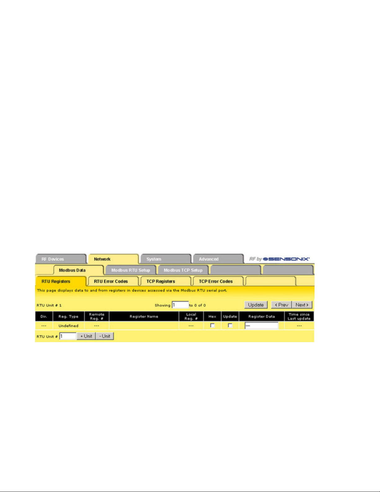
RTU Registers
The RTU Registers screen displays the Modbus register contents for RTU slave devices defined under the Modbus RTU set-up page.
To change the register data:
1. Enter a new register data value
2. Select the Update checkbox.
3. Click the Update button to send the new data to the device.
Hex checkbox
Prev and
Next
Select the Hex checkbox to view the data in
hexidecimal form (not recommended for
floating point values).
If there are more than 16 devices or rules/
maps, use the Prev and Next buttons to display the next screen of information.
Unit + and
Unit–
Update Clicking the Update button sends information
Scrolls through the list of RTU slave devices.
to the Ethernet Bridge or GatewayPro or retrieves information depending on which
checkboxes are selected: Change or Get/
Send All. Updating information does not save
rev. - www.bannerengineering.com - tel: 763-544-3164 25
Page 26

SureCross Web Configurator
Showing Lists the pages of registers for the selected
slave (RTU unit).
Update
checkbox
configuration information permanently to the
XML file.
Unless the Update checkbox is selected, this
register data will not be submitted to the
Ethernet Bridge or GatewayPro.
RTU Error Codes
The first occurrence of read and write errors are shown along with the map number that was processing when the error occurred.
Select the Reset checkbox to the left of the error codes and click the Update button to clear the error. If more than one error is active, the
next error code displays.
The right four columns display a count of errors for all maps for each device. Select the Reset checkbox left of the Total Messages
column and click Update to reset the counts. Click Update to view the most recent values.
RTU and TCP Error Codes (A/B Format)
Error codes (A/B format) indicate the following errors with the first number:
1. n/a for RTU (Transaction ID out of sync)
2. Exception code returned by remote device
3. Function code mismatch (bad packet)
4. Insufficient data (bad packet)
5. No response from remote device, timed out
6. CRC error in received packet
When A is code 2, indicating an exception code was returned, B indicates the exception as follows:
1. Illegal function code
2. Illegal data address (the requested register does not exist in the device)
3. Illegal data value
26 www.bannerengineering.com - tel: 763-544-3164 rev. -
Page 27

SureCross Web Configurator
TCP Registers
The TCP Registers page displays data mapped by the virtual server user map defined under Network > Modbus/TCP Setup > Server
Map.
This is a snapshot of what the remote client sees when the user map is enabled. The diagnostic info displays the connection status for
each available connection. A code of A/B where A is zero is an available connection, and B indicates the reason for closing (may be
normal TCP close). A value of A greater than zero and B equal to zero indicates an active connection.
TCP Error Codes
The TCP Error Codes page displays error codes encountered when processing Modbus Client reads and writes via the Modbus/TCP
connection.
rev. - www.bannerengineering.com - tel: 763-544-3164 27
Page 28

SureCross Web Configurator
Resetting Error Codes
The first occurrence of read and write errors are shown along with the map number that was processing when the error occurred. Check
the Reset box to the left of the error column and click the Update button to clear the error. If more than one error is active, the next error
code displays.
The right three columns display an error count for all maps for each device. Check the Reset box to the left of the Total Messages column
and click Update to reset the counts. Click Update to view the most recent data values.
RTU and TCP Error Codes (A/B Format)
Error codes (A/B format) indicate the following errors with the first number:
1. n/a for RTU (Transaction ID out of sync)
2. Exception code returned by remote device
3. Function code mismatch (bad packet)
4. Insufficient data (bad packet)
5. No response from remote device, timed out
6. CRC error in received packet
When A is code 2, indicating an exception code was returned, B indicates the exception as follows:
1. Illegal function code
2. Illegal data address (the requested register does not exist in the device)
3. Illegal data value
28 www.bannerengineering.com - tel: 763-544-3164 rev. -
Page 29

SureCross Web Configurator
Modbus RTU Setup Submenu
The Modbus RTU Setup submenu contains the read and write map screens for setting up the Modbus RTU Slave option. The two
screens contained within the Modbus RTU Setup tab apply only to the Ethernet processor on the GatewayPro or a DX83 device.
RTU Read Map
The RTU Read Map screen creates a map entry to read data from one or more remote Modbus RTU serial devices. Click on the map
number in the left column to view more detail and to insert or delete maps.
Maps entered on the RTU Read Map page only read data from remote devices into local registers. To write data to those remote devices,
go to the RTU Write Map tab.
This screen displays an abbreviated list of maps. Any parameter shown may be changed. To view and/or modify the complete set of
parameters, click on the map number shown in the left column and use the expanded RTU Read Map page. To submit changes, click the
Update button.
For each remote register to be read, enter the register type, remote register format, register number, remote unit number, and local
register number.
Local Register Number
Name The name is optional and used only for dis-
Prev and
Next
Remote
Register
Format
Remote
Register
Number
After the remote register is read and the data
multiplied by the scale factor, the data is written to the Local Register number.
play purposes. The name acts as an identifier
for a specific register map. Type in the name
in this screen.
If there are more than 16 devices or rules/
maps, use the Prev and Next buttons to display the next screen of information.
Select the format of the remote register from
integer, unsigned, double, float, or bit. An integer is a 16-bit (signed) number, an unsigned format is a 16-bit unsigned number, a
double refers to a double precision (32-bit)
value, a floating value is a floating point number, and a bit value is a single bit that can either be a 0 or a 1 (discrete value.)
The Remote Register entry is the register being read.
Remote
Type
Scale The raw data in the remote register is multiplied
Select a type from the following drop-down list:
none, coil (output), discrete input, input register,
or holding register. Banner Engineering’s SureCross™ slave devices use only input registers
and holding registers. When using slave devices
from other manufacturers, please refer to the
manufacturer’s documentation to determine what
I/O types they use.
• Coil (output). 1xxxx - Other slave devices,
write only, 1 bit
• Discrete Input. 3xxxx - Other slave devices,
read only, 1 bit
• Input Register. 3xxxx - SureCross™ slave
devices, read only, 16 bit
• Holding Register. 4xxxx - SureCross slave
devices, read/write, 16 bit
Selecting None for remote type negates the rule
even though it continues to appear in the list until
deleted. Unused rules at the end of the list always show None as the remote type. To prevent
these from displaying, reduce the number of
maps enabled.
by the scale factor to produce the data appearing
rev. - www.bannerengineering.com - tel: 763-544-3164 29
Page 30

SureCross Web Configurator
Remote
Unit #
(Slave ID)
The Remote Unit number is the slave ID of
the remote unit to be read. The value in this
register is then written to the local register listed.
Swapped
in the floating point register associated with the I/
O point.
Check the Swapped box to swap the byte orientation.
Update Clicking the Update button sends information to
the Ethernet Bridge or GatewayPro or retrieves
information depending on which checkboxes are
selected: Change or Get/Send All. Updating information does not save configuration information permanently to the XML file.
Expanded RTU Read Map
The expanded view of the RTU Read Map contains the same parameters as on the original page in addition to a few more parameters.
For each remote register to be read, enter the register type, remote register format, remote register number, and device number (remote
unit number). Referring to the screen image, the following parameters may be set using this screen:
Parameter Parameter
1 Register type 8 Offset
2 Remote register format 9 Local register number
3 Remote register number 10 Name
4 Device number (remote unit number) 11 Periodic poll time
5 Doubles swapper 12 Default value
6 Bit mask 13 Read fail count
7 Scale
When the remote register is read, data may be manipulated before being written to the local register. If a bit mask is entered (in hexadecimal), and the remote register type is signed or unsigned (16-bit data), the mask will be bit-wise logical AND-ed with the data, and the
30 www.bannerengineering.com - tel: 763-544-3164 rev. -
Page 31

SureCross Web Configurator
retained bits will be right justified in the result. The result is multiplied by the scale factor and added to the offset. The final result is written
to the local register number selected.
Delete
and Insert
Periodic Poll
Time
Prev
and
Next
Clicking the Delete button removes the rule or
map number shown in the Rule # or Map # box.
Clicking the Insert button inserts a new map
ahead of the map number shown. It is not necessary to use the Insert button to add maps to the
bottom of the list or to define any rule with None
as the register type. To add a map/rule to the
bottom of the list, increase the number of rules or
maps enabled.
Determines how often the Gateway Pro or Gateway/Ethernet Bridge pair read the remote registers of the Modbus slave device. Setting the periodic poll time to zero sets the Gateway Pro or
Gateway/Ethernet Bridge pair to read the remote
registers continually.
If there are more than 16 devices or rules/maps,
use the Prev and Next buttons to display the
next screen of information.
Read
Fail
Count
When the read fail count is not zero, the default
value is stored in the local register after the given number of read failures. Setting the read fail
count to zero disables the default and the register retains the most recent value.
Register
Type
Selecting None for register type negates the
map though it remains in the list until deleted.
Unused maps always show None as the type. If
the displayed maps are used and more are needed, increase the RTU Read Maps Enabled
number.
Update Clicking the Update button sends information to
the Ethernet Bridge or GatewayPro or retrieves
information depending on which checkboxes are
selected: Change or Get/Send All. Updating information does not save configuration information permanently to the XML file.
RTU Write Map
The RTU Write Map page creates a map entry that writes data to one or more remote Modbus RTU serial devices.
Maps on the RTU Write Map page only write data from the local register to the remote register listed. Use the RTU Read Map page to
read data from those remote devices.
Any parameters shown may be changed and submitted by clicking the Update button, but this screen displays only an abbreviated list of
the map parameters. To view and/or modify the complete set of parameters, click on the hyperlinked map number in the left column and
use the expanded RTU Write Map page.
For each local register, enter the register number, scale, remote type, remote register format, remote register number, and remote unit
number (device).
Delete
and Insert
Clicking the Delete button removes the rule or
map number shown in the Rule # or Map #
box. Clicking the Insert button inserts a new
map ahead of the map number shown. It is not
necessary to use the Insert button to add maps
to the bottom of the list or to define any rule
with None as the register type. To add a map/
Remote
Type
Select a type from the following drop-down list:
none, coil (output), discrete input, input register,
or holding register. Banner Engineering’s SureCross™ slave devices use only input registers
and holding registers. When using slave devices
from other manufacturers, please refer to the
manufacturer’s documentation to determine what
I/O types are used.
rev. - www.bannerengineering.com - tel: 763-544-3164 31
Page 32

SureCross Web Configurator
rule to the bottom of the list, increase the number of rules or maps enabled.
Local
Register
The data in the local register is multiplied by
the scale factor, then written to the remote register.
Name The name is optional and used only for display
purposes. The name acts as an identifier for a
specific register map. Type in the name in this
screen.
Prev and
Next
If there are more than 16 devices or rules/
maps, use the Prev and Next buttons to display the next screen of information.
Remote
Register
Format
Select the format of the remote register from
integer, unsigned, double, float, or bit. An integer is a 16-bit (signed) number, an unsigned
format is a 16-bit unsigned number, a double
refers to a double precision (32-bit) value, a
floating value is a floating point number, and a
bit value is a single bit that can either be a 0 or
a 1 (discrete value.)
Remote
Register
The Remote Register entry is the register being written to in the map.
Number
Remote
Slave ID
The Remote Unit number is the slave ID of the
remote unit to be written to.
(Unit #)
• Coil (output). 1xxxx, Other slave devices,
write only, 1 bit
• Discrete Input. 3xxxx, Other slave devices,
read only, 1 bit
• Input Register. 3xxxx, SureCross™ slave
devices, read only, 16 bit
• Holding Register. 4xxxx, SureCross slave
devices, read/write, 16 bit
Selecting None for remote type negates the rule
though it remains in the list until deleted. Unused
rules at the end of the list always show None as
the remote type. To prevent these from displaying, reduce the number of maps enabled on the
expanded view screen.
Scale The raw data in the local register is multiplied by
the scale factor to produce the data written to the
remote register.
Swapped
Check the Swapped box to swap the byte orientation.
Update Clicking the Update button sends information to
the Ethernet Bridge or GatewayPro or retrieves
information depending on which checkboxes are
selected: Change or Get/Send All. Updating information does not save configuration information permanently to the XML file.
Expanded RTU Write Map
Like the RTU Read Map expanded view, the RTU Write Map expanded view contains some of the same parameters as the RTU Write
Map primary view in addition to a few more parameters.
Refer to the Expanded RTU Read Map section for more information about these parameters (GUID-5EBD5A53-1BF9-4F16-
B92D-60E91D2E058C.xml).
32 www.bannerengineering.com - tel: 763-544-3164 rev. -
Page 33

SureCross Web Configurator
Modbus TCP Setup Submenu
Use the Modbus TCP Setup pages to specify the network address and optional device parameters of a remote Modbus/TCP device.
Example remote Modbus/TCP devices may include another Gateway device or any remote device using Modbus/TCP to communicate.
Devices
Use the Devices page to set up the network address and optional device parameters for a remote Modbus/TCP device that is linked to for
remote input and/or output.
Map the remote Modbus/TCP device’s input and/or output using the Client Read and Client Write Maps.
Connection Status. Connection status displays a non-zero error code when a socket error occurs. Possible errors include:
• 104 - Connection reset by peer
• 111 - Connection refused
• 113 - Connection aborted
• 114 - Network is unreachable
• 116 - Connection timed out
• 118 - Host is unreachable
• 119 - Connection in progress (connect unsuccessful and still trying)
• 205 - Could not get host IP by name
Default
Poll Period
Domain
Name
IP Address
Local
Name
Port If port is left set to zero, port 502 is used. To
The polling period defines how often, in seconds, this device (GatewayPro or Ethernet
Bridge) contacts the device listed and solicits
data.
The system may also look up an IP address
when given a domain name. If the IP address
is set to zero, the system attempts to find the
host by name.
Specify the IP address of the remote Modbus/
TCP device.
The local name is an optional field and is used
to refer to this device in other Web Configurator pages.
use a non-standard port number, enter the
number.
Swap
Double
Registers
The term swapped applies only to double or float
formats. Modbus registers are, by definition, 16
bits of data per register. Access to 32-bit data,
either 32-bit integer (double) or IEEE 754 floating point (float), is supported using two consecutive registers. Modbus protocol is inherently “big
endian,” therefore Modbus defaults to having the
high order register first for double and float formats. If the low order register comes first on the
accessed device, check the Swapped box.
If you have Swapped incorrectly, check the data.
When floating point data is reversed, a 1.0 becomes 2.2779508e-41, which rounds to zero. A
floating point 1.1 becomes negative 107609184.
If 32-bit integer data is reversed, 1 becomes
65536.
rev. - www.bannerengineering.com - tel: 763-544-3164 33
Page 34

SureCross Web Configurator
Unit
(Optional)
The unit or device number is an optional parameter and used primarily for organizational purposes.
Client Read Map
Use the Client Read Map tables to create maps that read data from the Modbus/TCP devices defined in the Devices page.
Maps entered on the Client Read Map page only read data from remote devices. To write data to those devices, go to the Client Write
Map page. For each remote register to be read, enter the register type, remote register format, register number, remote device, scale,
and local register number.
Any parameters shown may be changed and submitted by clicking the Update button, but this screen displays only an abbreviated list of
the map parameters. To view and/or modify the complete set of parameters, click on the hyperlinked map number in the left column and
use the expanded Client Read Map page.
Prev and
Next
If there are more than 16 devices or rules/
maps, use the Prev and Next buttons to display the next screen of information.
Local
Register
Number
After the remote register is read and the data
multiplied by the scale factor, the data is written to the Local Register number.
Name The name is optional and used only for dis-
play purposes. The names are defined in the
Devices page using the local name field.
Remote
Device
Remote
Register
Format
The local names from the Devices tab are listed in this drop-down list.
Select the format of the remote register from
integer, unsigned, double, float, or bit. An integer is a 16-bit (signed) number, an unsigned format is a 16-bit unsigned number, a
double refers to a double precision (32-bit)
value, a floating value is a floating point number, and a bit value is a single bit that can either be a 0 or a 1 (discrete value.)
Remote
Register
The Remote Register entry is the register
number being read in the mapping.
Number
Remote
Type
Select a Remote Type from the following dropdown list: none, coil (output), discrete input, input
register, or holding register. Banner Engineering’s
SureCross™ slave devices use only input registers and holding registers. When using devices
from other manufacturers, please refer to the
manufacturer’s documentation to determine what
I/O types are used.
• None
• Coil (output). 1xxxx - Other slave devices,
write only, 1 bit
• Discrete Input. 3xxxx - Other slave devices,
read only, 1 bit
• Input Register. 3xxxx - SureCross™ slave devices, read only, 16 bit
• Holding Register. 4xxxx - SureCross slave devices, read/write, 16 bit
Selecting None for remote type negates the rule
though it remains in the list until deleted. Unused
rules at the end of the list always show None as
the remote type. To prevent these from displaying,
reduce the number of maps enabled on the expanded view.
Scale The raw data in the remote register is multiplied
by the scale factor to produce the data appearing
34 www.bannerengineering.com - tel: 763-544-3164 rev. -
Page 35

SureCross Web Configurator
in the floating point register associated with the I/
O point.
Update
Clicking the Update button sends information to
the Ethernet Bridge or GatewayPro or retrieves information depending on which checkboxes are selected: Change or Get/Send All. Updating information does not save configuration information permanently to the XML file.
Expanded Client Read Map
Like the RTU Read Map expanded view, the Client Read Map expanded view contains some of the same parameters as the Client Read
Map primary view, in addition to a few more parameters.
Refer to the RTU Read Map expanded view section for more information about these parameters (GUID-5EBD5A53-1BF9-4F16-
B92D-60E91D2E058C.xml).
Client Write Map
Use the Client Write Map page to create a map entry that writes data from a local register to a remote Modbus/TCP server.
Maps on the Client Write Map page only write data from the local register to the remote register listed. Use the Client Read Map page to
read data from those devices.
Any parameters shown may be changed and submitted by clicking the Update button, but this screen displays only an abbreviated list of
the map parameters. To view and/or modify the complete set of parameters, click on the hyperlinked map number in the left column and
use the expanded Client Write Map page.
Data from the local register is multiplied by the scale factor, then written to the remote register. For each remote register, enter the register type, format, number, and location (device).
rev. - www.bannerengineering.com - tel: 763-544-3164 35
Page 36

SureCross Web Configurator
Local
Register
The data in the local register is multiplied by
the scale factor, then written to the remote
register.
Name The name is optional and used only for dis-
play purposes. Names are defined on the Devices page, local name field.
Prev and
Next
If there are more than 16 devices or rules/
maps, use the Prev and Next buttons to display the next screen of information.
Remote
Device
Remote
Register
Format
The local names from the Devices tab are listed in this drop-down list.
Select the format of the remote register from
integer, unsigned, double, float, or bit. An integer is a 16-bit (signed) number, an unsigned
format is a 16-bit unsigned number, a double
refers to a double precision (32-bit) value, a
floating value is a floating point number, and a
bit value is a single bit that can either be a 0
or a 1 (discrete value.)
Remote
Register
The Remote Register entry is the register
number being written to in the mapping.
Number
Remote
Type
Select a Remote Type from the following dropdown list: none, coil (output), discrete input, input
register, or holding register. Banner Engineering’s
SureCross™ slave devices use only input registers and holding registers. When using slave devices from other manufacturers, please refer to the
manufacturer’s documentation to determine what
I/O types are used.
• None
• Coil (output). 1xxxx - Other slave devices,
write only, 1 bit
• Discrete Input. 3xxxx - Other slave devices,
read only, 1 bit
• Input Register. 3xxxx - SureCross™ slave devices, read only, 16 bit
• Holding Register. 4xxxx - SureCross slave devices, read/write, 16 bit
Selecting None for remote type negates the rule,
though it remains in the list until deleted. To prevent unused rules from displaying, reduce the
number of maps enabled on the expanded view.
Scale The raw data in the local register is multiplied by
the scale factor to produce the data appearing in
the floating point register associated with the I/O
point.
Update
Clicking the Update button sends information to
the Ethernet Bridge or GatewayPro or retrieves information depending on which checkboxes are selected: Change or Get/Send All. Updating information does not save configuration information permanently to the XML file.
Expanded Client Write Map
Like the RTU Read Map expanded view, the Client Write Map expanded view contains some of the same parameters as the Client Write
Map primary view, in addition to a few more parameters.
Refer to the RTU Read Map expanded view section for more information about these parameters (GUID-5EBD5A53-1BF9-4F16-
B92D-60E91D2E058C.xml).
Server Map
The Server Map page sets up the register map for a virtual Modbus/TCP server, allowing a custom view of remote registers.
36 www.bannerengineering.com - tel: 763-544-3164 rev. -
Page 37

SureCross Web Configurator
Use the Server Map page to set up a copy of various remote register data to a specific, unused block of Modbus registers. For example,
copy the data in register 8 from all devices to a Modbus register block. This map is also referred to as the user map.
Bit Field and Fill. Defining the Bit field allows the compiling of register contents derived from multiple sources. The source data is limited
to the number of bits represented in the bit field (a hexadecimal value) and is shifted into the position represented by ‘1’ bits in the field.
Fill bits are logically OR’ed into the result before the server presents the data. Consecutive server map entries that reference the same
server address are OR’ed together and presented at that address. Duplicate map entries referencing the same server address but not
listed in consecutive order following the first instance are skipped. No special bit field processing occurs if the bit field is set to zero. Bit
fields apply to 16-bit integer or unsigned integer server registers only.
For example, a bit field entered as 00FF indicates a need for eight bits of the Local Register, mapped to the lower portion of the Mapped
Register Number. A bit field of FF00 still indicates a need for the lower 8 bits of the Local Register, but mapped to the upper portion of the
Mapped Register Number. For example:
Local Register Contents Bit Field Result Copied to Mapped Register
005A 0FF0 05A0
005A F0F0 00A0
005A 00FF 005A
005A FF00 5A00
1234 0F0F 0204
A second example is given below, using the Server Map screen.
The example screen image shows two local registers using the bit field to be copied to one mapped register. The result of the bit field
mapping when register 17 contains 005A and register 18 contains 003C is to map the results, 3C5A to register 500.
rev. - www.bannerengineering.com - tel: 763-544-3164 37
Page 38

SureCross Web Configurator
Custom
Registers Enabled
Delete
and Insert
Exclusivity
Local
Register
Number
Mapped
Register
Format
The Custom Registers Enabled parameter controls how many maps are enabled and displayed.
Clicking the Delete button removes the rule or
map number shown in the Rule # or Map # box.
Clicking the Insert button inserts a new map
ahead of the map number shown. It is not necessary to use the Insert button to add maps to
the bottom of the list or to define any rule with
None as the register type. To add a map/rule to
the bottom of the list, increase the number of
rules or maps enabled.
Enter the number of Modbus registers available
in your customized register mapping and select
the User Map Enabled checkbox to begin using
a customized map. Select the Map is Exclusive
checkbox if the access to registers outside this
map is prohibited. If the Map is Exclusive
checkbox is not selected, all local registers not
overlapped by the custom map will be accessible to the remote client.
The Local Register Number is the source of the
data.
Select the mapped register format: integer, unsigned, double, float, or bit. An integer is a 16bit (signed) number, an unsigned format is a
16-bit unsigned number, double refers to a double precision (32-bit) value, a floating value is a
floating point number, and a bit value is a single
bit that can either be a 0 or a 1 (discrete value.)
Name The name is optional and only used for display
purposes.
Prev
and
Next
Scale
Factor
and Offset
Swapping
Update Clicking the Update button sends information to
Zero
Fill
If there are more than 16 devices or rules/maps,
use the Prev and Next buttons to display the
next screen of information.
Optional fields, the Scale Factor and Offset value work together to convert register data. The
source data is multiplied by the scale factor and
added to the offset to produce the data in the
mapped server register.
By default, double registers in the DX80 are “big
endian;” the most significant bytes are in the first
register and least significant bytes are in the
second register. If remote clients accessing this
server at this IP address expect “little endian,”
select the Swap Double Registers checkbox.
Modbus protocol by definition is “big endian”
within each register, but the “endian” order of the
registers for 32-bit values is less standardized.
the Ethernet Bridge or GatewayPro or retrieves
information depending on which checkboxes are
selected: Change or Get/Send All. Updating information does not save configuration information permanently to the XML file.
Normally an attempt to read an undefined register returns an exception (error) code. To enable
reading of large data packets without nuisance
errors, zero filling null registers so that reading
an undefined register between valid defined registers returns zero data rather than an error.
Selecting None for the register format negates
the rule even though it continues to appear in
the list until deleted. Unused rules at the end of
the list always show None as the mapped register format.
Mapped
Register
Number
The mapped register number is the destination
register for the data to be copied to.
System Tab
The System tab contains system-wide settings and functions including system-level register information, data manipulation and calculations, and network set up instructions.
Data Submenu
The Data submenu accesses system-level register information.
Local Registers
The Local Registers tab displays the data in the local registers maintained by the GatewayPro or Ethernet Bridge.
38 www.bannerengineering.com - tel: 763-544-3164 rev. -
Page 39

SureCross Web Configurator
Default
Data
Hex
Checkbox
Prev and
Next
Register
Data
Server
Timeout
When the Server Timeout value is set to a
non-zero value, the default data is stored into
the local register when the server times out.
Select the Hex checkbox to view or enter values in hexadecimal (not recommended for
floating point).
If there are more than 16 devices or rules/
maps, use the Prev and Next buttons to display the next screen of information.
Displays the register data or can be used to
change the register data. To change the register contents, enter a new value, select the Update checkbox, and click the Update button.
When the Server Timeout value is set to a
non-zero value, the default data is stored into
the local register when the server times out. A
server timeout occurs when the timeout value
elapses without a remote server writing to this
register. A remote server writes to this register
when the DX80 device is acting as a Modbus
slave device.
Showing
Registers
Displays the beginning of the register range
currently displayed. To jump to a specific register, enter the register number in the Showing
Registers box and click the Update button.
Unsigned
Checkbox
Integers are 16-bit registers that may be signed
or unsigned. Unsigned values range from 0
through 65,535 and signed values range from
-32,767 through +32,767. This checkbox only
affects the way register information is displayed on the screen, not the way the data is
stored in the register. Select the Unsigned
checkbox to treat the register as unsigned. For
floating point registers, which start at register
1001 on the Gateway, the unsigned/signed option is ignored.
Update Clicking the Update button sends information
to the Ethernet Bridge or GatewayPro or retrieves information depending on which checkboxes are selected: Change or Get/Send All.
Updating information does not save configuration information permanently to the XML file.
Update
Check-
Select the Update checkbox and click the Update button to update the value.
box
rev. - www.bannerengineering.com - tel: 763-544-3164 39
Page 40

SureCross Web Configurator
Thresholds (Data Submenu)
The status of the threshold action maps displays on this Thresholds tab. The Threshold tab only displays information; no parameters are
changed here.
The true/false status may not reflect the correct result of the test. Because the indicated result is qualified by hysteresis and on-time or
off-time before taking effect, the anticipated result may be delayed.
Prev and
Next
If there are more than 16 devices or rules/
maps, use the Prev and Next buttons to display
the next screen of information.
Update
Clicking the Update button sends information to the
Ethernet Bridge or GatewayPro or retrieves information depending on which checkboxes are selected: Change or Get/Send All. Updating information
does not save configuration information permanently to the XML file.
Trend Data
The Trend Data tab displays the trending for all tracked registers.
Click the Graph link to view the last 250 data points recorded by trend tracking and stored in the Flash file system. When there are no
errors to report, the Graph status is normally zero. When errors occur, a negative number appears, referring to one of the codes in the
error code list.
Check the Reset box and click the Update button to reset the trend data, clear the graph, and reset the minimum and maximum tracking.
Prev and
Next
40 www.bannerengineering.com - tel: 763-544-3164 rev. -
If there are more than 16 devices or rules/
maps, use the Prev and Next buttons to display
the next screen of information.
Update
Clicking the Update button sends information to the
Ethernet Bridge or GatewayPro or retrieves information depending on which checkboxes are selected: Change or Get/Send All. Updating information
does not save configuration information permanently to the XML file.
Page 41

SureCross Web Configurator
Action Rules Submenu
The Action Rules submenu contains the rules regarding data manipulation and calculations.
Thresholds (Action Rules Submenu)
The main Threshold tab only displays the rules.
Click on the hyperlinked rule number in the left column to view the expanded threshold rule screen and to make changes to the rule.
Expanded Thresholds (Action Rules Submenu)
Referring to the screen image, the following parameters may be set using this screen:
Description Description
1 Source register 8 Hysteresis OFF time
2 Event name 9 Local destination register
3 Condition/qualification 10 Register to log the ON time to
4 Comparison fixed value 11 TRUE fixed value
5 Comparison local register 12 Local register
6 Hysteresis 13 FALSE fixed value
7 Hysteresis ON time 14 Local register
rev. - www.bannerengineering.com - tel: 763-544-3164 41
Page 42

SureCross Web Configurator
Threshold rules trigger actions based on events. The event occurs when a source register meets the criteria defined by the rule. The
result of the event can be setting another register to a value as indicated in the rule template, sending an e-mail notification, sending a
text message to a cell phone, or logging an event or data to a log file.
Comparison
Fixed
Value /
Comparison
Local
Register
Condition/
Qualification
Delete
and Insert
Event
Name
Hysteresis
Enter either the comparison fixed value or comparison local register number to compare to.
Qualifications are optional and enabled only
when values are nonzero.
Select a condition/qualification test by dropping
down the list and selecting how to compare.
Selecting Changed By in the condition/qualification drop-down list selects a rate of change test.
If the source register has changed by the value
specified as the comparison fixed value or the
value contained in the local register, the test is
true. The minimum ON time on the following line
applies. The test is true if the source register
has changed by the specified amount in this
time period. The ON time is used this way only
for the Changed By test. Normally the ON time
is used as previously described. The absolute
value of the change found in the local register is
tested, so the specified value (or delta) to test
against should always be a positive number.
Clicking the Delete button removes the rule or
map number shown in the Rule # or Map # box.
Clicking the Insert button inserts a new map
ahead of the map number shown. It is not necessary to use the Insert button to add maps to
the bottom of the list or to define any rule with
None as the register type. To add a map/rule to
the bottom of the list, increase the number of
rules or maps enabled.
The event name is optional and used only for
display and/or identification purposes.
How hysteresis is applied depends on the comparison. If a greater than test returns a ‘true,’ the
test does not return to false until the local register is less than the test value by a margin of at
least this hysteresis value. If a less than test is
‘true,’ it will not return to false until the local register is greater than the test value by a margin of
at least this hysteresis value.
Hysteresis ON
and OFF
Time
The hysteresis ON time and hysteresis OFF
time, if specified, determine how long the condition must be true (ON time) or false (OFF
time) before the true or false response is actually taken. Times are given in HH:MM:SS format (hours, minutes, seconds).
Local
Destination Register
To define the response, select which local register, or destination register, to apply the response to. Typically the destination register
links to an output. It isn’t necessary to apply
the result to any destination register when only
reporting the event via a trap or e-mail message. Leave the destination register set to zero
and ignore the last two lines on the screen.
The test result is processed as true or false
without the destination register specified.
The first line after the local destination register
number is the response when the condition is
true, and the following line is the response
when the condition is false. Either the source
register is copied, a TRUE fixed value is applied, or another register is used to provide the
data written to the destination register.
Source
Register
To begin defining a new rule, enter in a source
register.
Entering zero as a source register negates the
rule even though it remains in the list until deleted. Unused rules at the end of the list always
show zero as the source register. To prevent
these from displaying, reduce the number of
rules enabled. If the displayed rules are used
and more are needed, increase the enabled
number.
Update Clicking the Update button sends information
to the Ethernet Bridge or GatewayPro or retrieves information depending on which checkboxes are selected: Change or Get/Send All.
Updating information does not save configuration information permanently to the XML file.
Trending
Use the Trending tab to set up statistical tracking of specific registers.
42 www.bannerengineering.com - tel: 763-544-3164 rev. -
Page 43

SureCross Web Configurator
To track a register:
1. Enter the register number to be tracked in the Tracked Register # field.
2. Select destination registers for the Average Register, Min Register, and Max Register, by entering unassigned register numbers in
the supplied fields. Unassigned integer and floating point registers are listed at the bottom of the screen. To automatically assign
the result registers, click the Auto Allocate button. The default starting registers are the first registers not allocated to I/O points.
3. Select how often to reset the statistics from the drop-down list. The reset values can be when logged, daily, or hourly. Selecting
when logged resets the calculations when the values are logged to a file.
4. Enter the time period for the data sampling and the number of slices, or samples, within that time period.
5. Click the Update button to submit the changes.
When tracking any registers, the average, minimum and maximum registers must be assigned. Do not leave these values set to zero
unless no registers are tracked.
The trend data is updated at the period entered and this period is divided into the number of slices, or samples. A sliding window average
of this number of slices is maintained and this filtered value is processed as the trend data. The minimum data value is the average
lowest value for each period sampled. The maximum data value is the average highest value over each period sampled.
All result registers for a given tracked register are reset when any one of the result registers is logged if when logged is selected for reset.
However, all resets are performed after the entire log record has been compiled for the given log cycle to avoid logging partial results.
Delete
and Insert
Clicking the Delete button removes the rule or
map number shown in the Rule # or Map # box.
Clicking the Insert button inserts a new map
ahead of the map number shown. It is not necessary to use the Insert button to add maps to the
bottom of the list or to define any rule with None
Update
Clicking the Update button sends information to the
Ethernet Bridge or GatewayPro or retrieves information depending on which checkboxes are selected: Change or Get/Send All. Updating information
does not save configuration information perma-
nently to the XML file.
as the register type. To add a map/rule to the bottom of the list, increase the number of rules or
maps enabled.
Prev
and
Next
If there are more than 16 devices or rules/maps,
use the Prev and Next buttons to display the next
screen of information.
Cascade
Use the Cascade tab to configure the cascading of the registers: data from the source register is copied to the destination register(s)
rev. - www.bannerengineering.com - tel: 763-544-3164 43
Page 44

SureCross Web Configurator
Enter the single destination register or a range of destination registers to copy the source register to. If no last destination register is
entered, only a single destination register is used.
Do not use the same source register more than once in the cascade rules. To copy a register’s contents to multiple, non-consecutive
registers, only use the primary source register once. To copy the same contents to additional registers, use the previous destination
register as the second rule’s source register and ‘daisy-chain’ the register contents. For example, do not create three rules to copy register 5’s contents to register 6, 14, and 18. Instead, create one rule to copy register 5’s contents to register 6, a second rule to copy register
6’s contents to register 14, and a third rule to copy register 14’s contents to register 18.
Entering a zero as a source register negates the rule even though it remains in the list until deleted. Unused rules at the end of the list
always show zero as the source register. To prevent these from displaying, reduce the number of rules enabled.
Delete
and Insert
Clicking the Delete button removes the rule or
map number shown in the Rule # or Map # box.
Clicking the Insert button inserts a new map
ahead of the map number shown. It is not necessary to use the Insert button to add maps to the
bottom of the list or to define any rule with None
as the register type. To add a map/rule to the bottom of the list, increase the number of rules or
maps enabled.
Prev
and
Next
If there are more than 16 devices or rules/maps,
use the Prev and Next buttons to display the next
screen of information.
Calculate
Use the Calculate tab to set up simple calculations on the register data.
Update
Clicking the Update button sends information to the
Ethernet Bridge or GatewayPro or retrieves infor-
mation depending on which checkboxes are selec-
ted: Change or Get/Send All. Updating information
does not save configuration information perma-
nently to the XML file.
Entering none as the operation negates the rule even though it remains in the list until deleted. Unused rules at the end of the list always
show none as the operation. To prevent these from displaying, reduce the number of rules enabled.
44 www.bannerengineering.com - tel: 763-544-3164 rev. -
Page 45

SureCross Web Configurator
To establish calculations, select the operation from the drop list. All operations except logical NOT operations require two operands.
Enter the register numbers as applicable. Some operations are valid for ranges of registers. Select and or thru to select two registers or
multiple registers in a range. Average, sum, and logic operations are valid for ranges of multiple registers.
Constants
Use the Constants tab to define values written once to the assigned registers when the device starts up.
Enter the value and the local register number to which the constant should be written. Each constant writes to the selected register only
once at startup.
Entering zero as the value negates the rule even though it remains in the list until deleted. Unused rules at the end of the list always show
zero as the value. To prevent these from displaying, reduce the number of rules enabled.
Delete
and Insert
Prev
and
Next
Clicking the Delete button removes the rule or
map number shown in the Rule # or Map # box.
Clicking the Insert button inserts a new map
ahead of the map number shown. It is not necessary to use the Insert button to add maps to the
bottom of the list or to define any rule with None
as the register type. To add a map/rule to the bottom of the list, increase the number of rules or
maps enabled.
If there are more than 16 devices or rules/maps,
use the Prev and Next buttons to display the next
screen of information.
Update
Clicking the Update button sends information to the
Ethernet Bridge or GatewayPro or retrieves infor-
mation depending on which checkboxes are selec-
ted: Change or Get/Send All. Updating information
does not save configuration information perma-
nently to the XML file.
Setup Submenu
Tabs under the Setup submenu control general system parameters.
Config File
The Config File tab manages the configuration files.
All configuration changes are lost the next time power cycles if you did not click the Save or Save As buttons to write those change to the
XML file in non-volatile memory (Flash file).
When the flash memory updates, there is a delay of several seconds.
If you upload a file, make changes to the parameters on your PC, and re-upload the same file, the browser displays the old cached file.
Find the option among the browser settings to delete cached files from the PC and re-upload the file. In some cases, exit and restart the
browser.
rev. - www.bannerengineering.com - tel: 763-544-3164 45
Page 46

SureCross Web Configurator
Browse Selects a file for upload from the PC. Once se-
lected, click the Upload button to complete the
process.
Confirm
and Restart
Select the Confirm checkbox and click the Restart button to re-boot the system. Power is not
cycled to the hardware, but the processor reboots as if the power cycled. One example use
of this function is to remotely change a device’s
IP address and force a reboot (only the root
user can do this). Upon restart, because the IP
address was changed and the device updated,
this page will not reload and the HTTP connection is lost.
Delete Removes the file listed in the Local file directory
drop-down list from the directory. Clicking the
Delete button does not bring up a file list and
does not ask if you are sure you want to delete
the file.
Load Loads the selected file in the local file directory
into the local memory. Settings within the web
pages reload from the file and take effect immediately. This does not send any data to the
DX80 radio devices. Any parameters changed
within the web pages but not saved to the XML
file are lost.
Save Stores the current Web Configurator contents to a
flash memory file. The configuration overwrites
the selected file in the local file directory.
SaveAsStores the Web Configurator contents to a new
flash memory file as defined next to the Save As
button. When naming the file, include the .xml file
extension because this interface will not add the
file extension automatically. Do not use more than
16 characters in the file name (excluding
the .XML extension) and use only alphanumeric
characters.
Start-upSelects a different start-up configuration file. The
selected file is the flash memory file automatically
loaded during power-up. Before setting a file as
the startup file, first verify the XML file properly
loads.
View Displays the selected file. The file should be an
XML file, and the browser recognizes it as such if
the file is properly formatted.
Network
The Network tab contains the IP address set-up information. Use this page to change the IP address of the device or to enable EtherNet/
IP.
To change the IP address of this device, enter the address, subnet mask, and gateway, then click the Change IP button. This change
takes effect after the next reboot.
46 www.bannerengineering.com - tel: 763-544-3164 rev. -
Page 47

SureCross Web Configurator
Set the IP address to 255.255.255.255 to use Dynamic Host Configuration Protocol (DHCP) to obtain an IP address upon power-up. The
IP address change takes effect on the next power cycle or when the Restart button is clicked on the Config File page. After changing the
IP address of the DX80 device, print this page for your records.
The Refresh button only updates the information shown on this page, it does not submit a DHCP renewal request. DHCP renewal is
automatic.
The default port for web page serving is 80. To change this port, enter the port number and click the Set Port button. This change takes
effect on the next power-up. If the port is anything other than 80, the port number must be included in the URL. For example, if http://
10.0.0.101/ is normally used to access the Configurator when the port is set to 80 and the port is changed to 8215, use http://
10.0.0.101:8215/ to access the Configurator. (Note: The port change is accepted only by the root login, not the system login.)
• User name: root
• Password: sxi
If the Modbus and Telnet services are not used, disabling these ports improves network security. Disable these ports by entering zero
as the port. The HTTP port cannot be disabled - if set to zero, it will revert back to the default value of 80.
To use domain names instead of a static IP address, supply the IP address of at least one DNS server (Static DNS1 or 2). The DNS
server must be at a static IP address. These changes take effect immediately. Note: If you are using DHCP, set the Static DNS1 and
DNS2 addresses to 0.0.0.0 because the DHCP supplies the DNS addresses.
The numbers shown to the right of the input windows are the actual numbers in the system. For example, entering an IP address of
255.255.255.255 causes the system to acquire a dynamic IP address via DHCP. The IP address shown to the right is the currently
leased IP address. When DHCP is used, static DNS entries are ignored and the actual DNS entries provided by DHCP are shown.
When using a Dynamic DNS service to keep track of this device on the Internet, select the service type, enter the host name the service
uses for this device, and enter the user name and password associated with the update service. Click the Apply DNS button to register
this information. Save the configuration file to retain this data.
DDNS status should normally show OK or No update needed. It may show Local IP not checked yet for a short time after booting up. If it
shows Tentative and a reply of nochg, an update was forced with no changes to actually register. Repeated nochg occurrences is regarded as abuse by the dynamic DNS service(s), and a third occurrence is treated as a local error condition.
rev. - www.bannerengineering.com - tel: 763-544-3164 47
Page 48

SureCross Web Configurator
Any occurrence of a serious error puts the DDNS update in the Suspended state. If this occurs, resolve the problem and restart the
system or click Reset DNS. DO NOT click Reset DNS without knowing the problem is resolved. Repeated attempts to update DNS inappropriately may result in your host name being blocked. Clicking Reset DNS results in an immediate IP verification and attempt to reupdate DNS. The DNS server considers repeated updates resulting in no change (nochg reply) to be abuse. Repeated IP verification
(more frequently than once every 10 minutes) is also considered abuse.
Connection errors are internal network related errors and include:
• 2001 - General socket error
• 2005 - Could not reach local DNS to look up remote host
• 2006 - HTTP client aborted a web session
• < 200 - Unexpected network errors. Contact Banner Engineering if these errors occur.
Error messages that may be returned by the dynamic DNS service(s), noted as last reply, include:
• badauth - The user name and/or password does not match the host name
• nohost - The host name specified does not exist
• notfqdn - The host name is not a fully qualified domain name (not in the form of name.domain.com)
• !yours - The host name does exist, but not under the user name given
• abuse - The host name given is blocked for abuse.
Error messages returned by the dynamic DNS service(s) that require the attention of Banner Engineering include:
• badsys - The sycodestem is not valid
• badagent - The user agent is not specified or is blocked for non-conformance to specifications
• !donator - Invalid option specified
• numhost - Too many or too few hosts found
Error messages indicating a DDNS server error will be either dnserr or 911. In both cases, wait a minimum of one hour before restarting
the system and/or contact the DDNS service to see when the problem will be resolved.
EtherNet/IP
By default the Ethernet Bridge and GatewayPro systems communicate with a host system using Modbus/TCP.
The system can also use EtherNet/IP. To enable the system to use EtherNet/IP, you must be logged in as the “root” user.
1. Log in using the following user name and password. User name: root; Password: sxi.
2. At the bottom of the System > Setup > Network page is a checkbox to enable EtherNet/IP. Only select this box if the GatewayPro
system is running on an EtherNet/IP network. This change cannot be enabled from a login other than the “root” login.
3. After selecting the EtherNet/IP Enabled box, click the Set Ports button to save any changes made to the HTTP Port, Modbus Server Port, Telnet Port, and EtherNet/IP Enabled checkbox.
4. Cycle power to the Ethernet Bridge or GatewayPro to complete this update. After the device powers up, the changes should be
registered.
Sequence Numbers
The Omron PLC requires using sequence numbers within the Ethernet/IP packets. When using an Omrom PLC, set the radio button
selection at the bottom of the configuration page to "Always Increment."
48 www.bannerengineering.com - tel: 763-544-3164 rev. -
Page 49

SureCross Web Configurator
User
The User page changes the log-on password.
The current user’s name is displayed. To change the password, enter the old password, the new password, and confirm the new password by entering it again. Click the Accept button to submit the change. This change takes effect immediately.
Admin - Root Login
This second view of the User screen shows the screen when logging on using the admin/root login. Only the root user can enter user
names and passwords, change the privilege levels, and set IP address filters.
• User name: root
• Password: sxi
If the IP filter is a non-zero valid IP address, the user may only log in from that IP address. After making changes to this screen, select the
Confirm Change checkbox, then click the Change button to submit the changes.
Time and Date
Use the Time and Date page to change the system’s internal clock and calendar.
rev. - www.bannerengineering.com - tel: 763-544-3164 49
Page 50

SureCross Web Configurator
Click the Refresh button to view the current time. Enter a new time and click the Change button to set the clock/calendar. Use the same
string format observed when changing time/date.
To apply Daylight Saving Time:
1. Select the rules as needed.
2. Select the 'Is in effect now' checkbox if Daylight Saving Time is currently in effect and select the Is enabled checkbox to enable
Daylight Saving Time.
3. Click the Update button.
The time and date are maintained in the battery-backed real-time clock chip. Daylight saving time settings are saved in the configuration
file. To retain the daylight saving time settings through a power cycle, save the configuration file.
The scheduler may reference the astronomical clock instead of time of day. To set the astronomical clock, set local time and enter the
location information. North is positive for latitude, and east is positive (west is negative) for longitude.
Time zone is offset from GMT, 0 through 24, moving west around the world. As an example, Chicago is at latitude +41.83, longitude
-87.75, time zone +6. Time zones for the Banner devices are set up with west of GMT as positive numbers.
Sunrise and sunset calculations are typically within one to two minutes of those calculated by the US Naval Observatory. Go to the http://
geonames.usgs.gov/pls/gnispublic/ (US Geological Survey website) to look up the latitude and longitude of almost any US location.
Advanced Tab
The Advanced tab contains options for scheduling, logging data, and setting up automatic alerts.
Scheduler Submenu
The Scheduler page contains the pages for setting up weekly schedules, on demand schedules, and any holidays requiring special
schedules.
50 www.bannerengineering.com - tel: 763-544-3164 rev. -
Page 51

SureCross Web Configurator
Weekly Schedule
Use the Weekly Schedule page to manage weekly activities.
Before setting any schedules, verify the system’s time and date are accurately set in the System > Setup > Time and Date tab.
During the On Time, the On Value is applied to the given register. The remainder of the time, the register is set to the Off Value. The On
and Off Values are applied once at the start of the On Time, when the system is rebooted, and when the system clock is changed
(System > Setup > Time and Date screen).
Astronomical Clock
The astronomical clock will not work unless latitude, longitude, and time zone are set in the Time and Date tab.
To reference the astronomical clock instead of fixed time of day, enter DAWN or DUSK in place of the HH:MM:SS on and off times. An
offset in minutes may also be included. To specify one half hour after sunrise, enter dawn+30. To specify one half hour before sunset,
enter dusk-30, etc. Upper/lower case is ignored, but do not include any spaces in the dawn/dusk string.
Duplicating and Schedule
Instead of duplicating a schedule entry to activate multiple outputs, make a single schedule entry that applies to a single register then
cascade that register to any number of other registers with cascade rules set up on the System > Action Rules > Cascade page.
Weekly Schedule, Holidays Expanded View
Access the holiday expanded view by clicking the Holidays link on the main Weekly Schedule page.
The schedule entry affected shows on the first line. The remainder of the page allows you to add and remove defined holidays from this
schedule event.
Excluding Holidays
To exclude holidays from the scheduled event:
1. Select a holiday from the Available Holidays list.
2. Click the Add button.
3. Click on the Exclude radio button.
Once a holiday is added to the schedule, the scheduled event that normally happens on the selected days will not occur if one of the
selected days falls on one of the excluded holidays.
In the example screen shown below, six holidays are excluded from the scheduled event #1 when they fall on a weekday.
rev. - www.bannerengineering.com - tel: 763-544-3164 51
Page 52

SureCross Web Configurator
Including Holidays
To include holidays in the scheduled event:
1. Select a holiday from the Available Holidays list.
2. Click the Add button.
3. Click on the Include radio button.
If the selected Holiday falls on a day not selected with the checkboxes, selecting the Include button includes that Holiday in the schedule
regardless of the day of the week it falls on.
Ignoring Holidays
To perform the scheduled event regardless of holidays, remove the holiday from the Selected Holidays field. To remove:
1. Click on the desired holiday.
2. Click the Remove button. The Remove button does not remove the holiday from the list. The Remove button only tells the system
to disregard a particular holiday and process the schedule event normally.
Other Commands
Prev and
Next
If there are more than 16 devices or rules/
maps, use the Prev and Next buttons to display
the next screen of information.
Update
Clicking the Update button sends information to the
Ethernet Bridge or GatewayPro or retrieves information depending on which checkboxes are selected: Change or Get/Send All. Updating information
does not save configuration information permanently to the XML file.
On Demand
Use the On Demand page to set up scheduled events that occur only once instead of daily.
52 www.bannerengineering.com - tel: 763-544-3164 rev. -
Page 53

SureCross Web Configurator
The starting time and date (ON Time/Date) determine when the ON Value is applied to the given register. The ending time and date (OFF
Time/Date) determine when the ON period ends. The OFF Value is applied at the end of the ON Time.
After an On Demand event has passed, it should be removed from the list. The expired event remains included in the list until it is deleted, serving as a record of a past event.
To reference the astronomical clock instead of fixed time of day, enter DAWN or DUSK in place of the HH:MM:SS on and off times. An
offset in minutes may be included. To specify one half hour after sunrise, enter dawn+30. To specify one half hour before sunset, enter
dusk-30, etc. Upper and lower case is ignored, but do not include any spaces in the dawn/dusk string. The astronomical clock will not
work unless latitude, longitude, and time zone are set in the System > Setup > Time and Date tab.
Delete
and Insert
Clicking the Delete button removes the rule or
map number shown in the Rule # or Map # box.
Clicking the Insert button inserts a new map
ahead of the map number shown. It is not necessary to use the Insert button to add maps to the
bottom of the list or to define any rule with None
Update
Clicking the Update button sends information to the
Ethernet Bridge or GatewayPro or retrieves information depending on which checkboxes are selected: Change or Get/Send All. Updating information
does not save configuration information perma-
nently to the XML file.
as the register type. To add a map/rule to the bottom of the list, increase the number of rules or
maps enabled.
Prev
and
Next
If there are more than 16 devices or rules/maps,
use the Prev and Next buttons to display the next
screen of information.
Holidays
Use the Holidays page to define the holidays appearing in the expanded Weekly Schedule list.
After holidays are established, use the holidays and the Weekly Schedule page to create exceptions to weekly schedules.
rev. - www.bannerengineering.com - tel: 763-544-3164 53
Page 54

SureCross Web Configurator
For example, if the office doors should be opened automatically at 8 a.m. every weekday, use a holiday schedule to override the normal
schedule on Christmas and New Year’s Day to keep the office locked.
To create a holiday:
1. Enter the holiday name.
2. Enter an on time, on date, off time, and off date. Set the on time to begin the holiday one second after the day begins and end the
holiday one second before the day ends.
3. Click the Update button to submit the information to the Ethernet Bridge. Once saved, the holiday will be listed in the holidays list
on the Weekly Schedule page.
As with any changed parameters, to save the changes to the XML file, go to the System > Setup > Config File page and click the Save
button. Changes made by clicking an Update button are temporary until the changes are saved permanently into the configuration file.
Up-
Clicking the Update button sends information to the
date
Ethernet Bridge or GatewayPro or retrieves information depending on which checkboxes are selected:
Change or Get/Send All. Updating information does
not save configuration information permanently to
the XML file.
Data Logger Submenu
The Data Logger submenu contains the tabs used to create log files, establish events to log, and maintain the log files.
Log Files
Use the Log Files page to select a directory location (RAM0 or FLASH0) and file name for the log file. The system allows a fixed number
of log files. Use this page to assign a location and name to each log file used.
Log files are a CSV formatted text file with one line per data record. The first record is a header record naming all the registers contained
in the subsequent records. All remaining records are a set of data points, one value per register selected on the Data Points page, per
line in the file. Another line is added to the file for each logging of data per the rate set in the Log Files page.
54 www.bannerengineering.com - tel: 763-544-3164 rev. -
Page 55

SureCross Web Configurator
One event log and three data logs may be created. The event log saves events based on changes occurring in defined registers. The
data logs store register data based on a periodic rate defined by the user. Select the event log or one of the three data logs using the
Next and Prev buttons.
Enable
Select the checkbox to turn on the data logger.
Logging
File
Name
The file name must be contain no more than
eight characters and include the file extension .txt. Only alpha-numeric characters are allowed in the file name.
Log
Rate
The data logger logs at the rate given in
HH:MM:SS (hours, minutes, seconds). Logging
is disabled if the rate is zero. To activate continuous logging, set the log only when register
number is zero, the Enable Logging box is selected and the rate is not zero. To tie data logging to a schedule, select the Enable Logging
checkbox and verify the log only when register
number contains a valid local register number
with content greater than zero.
Prev
and
Scrolls through the log file types. The system allows for one event log and three data logs.
Next
File Names and Storage
Reset
Resets status error messages or conditions.
Errors
Status Displays a complete list of error conditions. For a
list of error codes, refer to Appendix B, Error Codes.
Update Clicking the Update button sends information to
the Ethernet Bridge or GatewayPro or retrieves
information depending on which checkboxes are
selected: Change or Get/Send All. Updating information does not save configuration information permanently to the XML file.
The file name entered is the first part of the generated name. The file creation date in the format YYYYMMDD is appended to the supplied name, allowing multiple files with the same user-supplied name to have unique file names. If the name is changed after data is
logged with the old name, manually delete the old files from the File List page. The Discard Oldest option only finds files with the same
name listed under the File Name.
rev. - www.bannerengineering.com - tel: 763-544-3164 55
Page 56

SureCross Web Configurator
Log files are saved to either RAM or FLASH memory. Log files stored in RAM are lost when the system power cycles. The RAM area is
directory RAM0 with a capacity of 1000KB (1 Megabyte). The FLASH area is directory FLASH0 with a capacity of 256KB. This FLASH0
area is shared with configuration files and program files.
Resource Allocation
To avoid filling a log file and losing data, allocate the system resources. A new log file may be started daily, weekly, or when the existing
data file reaches a specified size. When a log file is filled, have the data log file automatically e-mailed as an attachment or use FTP to
retrieve the file. To have the completed log file automatically e-mailed, enter a recipient’s e-mail address (myname@myplace.com) and
optional subject and message.
Discarding the Oldest Files
To automatically discard the oldest data logs when system resources are exhausted, check the discard oldest radio button. This discards
the oldest file with the name shown in the File Name box. This rule applies independently for each log file rule set.
The specific rules for resource management are as follows:
If a file is full (i.e. its size setting is met), disregard the schedule, e-mail the file to the listed recipients, and request a new file. Until the file
fills, check the schedule. If the log file should be e-mailed now because of daily schedule settings, e-mail the file and request a new file.
The e-mail command only applies if e-mail is configured, but the new file request always applies.
When a new file is requested, check the discard oldest or stop logging setting. If discard oldest is selected, add up all log file sizes. If this
much free space is not available, delete the oldest file with a name prefix matching the log configuration requesting a new file. If there is
only one (or fewer) older file, revert to stop logging rules. If stop logging is selected (by configuration or by default), verify there is room
for 50% of this file. If so, create the file. If not, disable this log.
Data Points
Use the Data Points page to select which local registers are logged by each of the available data loggers.
All the available local registers are listed on this page. Select the appropriate checkbox to include this data in one of the three log files.
56 www.bannerengineering.com - tel: 763-544-3164 rev. -
Page 57

SureCross Web Configurator
Clear All
and Set
All
Selecting one or more of the checkboxes directly to the right of the Clear All button and clicking
the Clear All button clears all selected checkboxes in that column. Similarly, clicking the Set
All button sets all checkboxes in the column
checked next to the buttons. Only named registers may be checked or unchecked; unnamed
registers are assumed to be unused. After a Set
All or Clear All command, any checkboxes may
be individually selected or deselected as nee-
Prev
and
Next
Update
Scrolls through the registers of the device listed
to the left of the Showing box.
Clicking the Update button sends information to
the Ethernet Bridge or GatewayPro or retrieves
information depending on which checkboxes are
selected: Change or Get/Send All. Updating information does not save configuration information
permanently to the XML file.
ded.
Include
Time/
Date Per
Select the Include time/date per record checkbox to include a time and date stamp for each
record logged to the log files.
Record
Events Logged
Use the Events Logged page to select which events are logged to a file.
Events are established in the list of rules found in System > Action Rules > Thresholds tab. Use the Thresholds page to establish the test
criteria that defines true and false. It is not necessary to set a destination register to any particular value in a threshold rule.
The result records to the event logger regardless of any other action taken as a result of the action or threshold rule. The list shown on
this page reflects the defined threshold rules.
Event records are stored in a CSV format text file. Each record includes time/date, event number, and true/false active state. If the Verbose Log checkbox is selected, the records also include the event name string, register number, register value, test type, and test value.
Prev
and
Next
Update
Scrolls through the threshold events established
on the System > Action Rules > Thresholds, Ex-
panded View page.
Clicking the Update button sends information to
the Ethernet Bridge or GatewayPro or retrieves
Verbose
Log
Selecting a Verbose log sets the records to include the event name string, register number,
register value, test type, and test value.
information depending on which checkboxes are
selected: Change or Get/Send All. Updating information does not save configuration information
permanently to the XML file.
File List
The File List tab lists the saved data and event log files.
rev. - www.bannerengineering.com - tel: 763-544-3164 57
Page 58

To copy a data log file from this page, right click on the file name link and select Save As in the web browser. The files save in CSV
format text files that may be imported into MS Excel.
SureCross Web Configurator
Delete To delete the files, select the checkbox for
the unwanted file then click the Delete button.
Prev and
Next
Scrolls through the pages of event and log
files.
Refresh Click the Refresh button to refresh the screen
image. This updates any information on the
screen that may have changed on the device.
E-mail Alerts Submenu
Use the E-mail Alerts submenu to set up e-mail alerts, recipients lists, and the mail servers configuration pages.
Recipients
Use the Recipients page to define the e-mail recipients and to select the message format: e-mail or cell phone text message.
Three recipients lists can be generated using this screen. E-mail messages (or cell phone messages) are triggered by events selected
using the Events screen. These events are set up using the System > Action Rules > Thresholds screen.
As shown in the Showing box, only three recipient/subject line groups can be created for e-mail and text message alerts. To send the
same message to multiple people, separate the e-mail addresses with semicolons.
58 www.bannerengineering.com - tel: 763-544-3164 rev. -
Page 59

SureCross Web Configurator
Checking the Include Standard Message box includes either the Default E-Mail Message or Cell Phone Message (whichever is selected).
Select the Include Custom Message checkbox to include a custom message along with the default message.
The standard auto-generated cell phone message is limited to 160 characters. Selecting both the standard cell phone message and a
custom message will exceed this limit. To send a custom cell phone message, exclude the standard message to keep within the typical
160 character limit.
Prev and
Next
Use the Prev and Next buttons to scroll
through the three groups of e-mail recipients.
Update
Clicking the Update button sends information to the
Ethernet Bridge or GatewayPro or retrieves information depending on which checkboxes are selected: Change or Get/Send All. Updating information
does not save configuration information permanently to the XML file.
E-Mail Messages
Because only three groups of recipients can be created, more than one e-mail address can be listed in the Recipients box if the names
are separated by semicolons. To differentiate the messages each group receives, click the Next button to enter another e-mail address
and select another type of message notification. Each name should be in the form of myname@mycompany.com.
Cell Phone Text Messages
To send a text message to a cell phone, enter the e-mail address in the following format: 10DigitNumber@CellCarrierDomain.com for
SMS-to-text capable cell phones. The domains for common cell phone carriers are:
• Alltel. @message.alltel.com
• AT&T. @txt.att.net
• Nextel. @messaging.nextel.com
• Sprint. @messaging.sprintpcs.com
• SunCom. @tms.suncom.com
rev. - www.bannerengineering.com - tel: 763-544-3164 59
Page 60

SureCross Web Configurator
• T-Mobile. @tmomail.net
• VoiceStream. @voicestream.net
• Verizon. @vtext.com
Click the Send Test button to send a message to the defined recipient, testing the settings defined for the POP3/SNMP servers as well as
the DNS server. The most common problem is usually the e-mail user and password setup or the system contact. Contact your network
administrators for questions concerning access to outside providers.
Sample Message
An example of a default auto-generated message is:
• This is an automated e-mail alert originating from ‘Cooler System’ at ‘Winky’s Kitchen’ at 14:45:10 02/23/2006.
• The event named ‘Freezer Failure’ with a test criteria of ‘Greater than or equal to’ a value of 28.0000 tested true for register 44,
‘Freezer Temperature’ with a value of 33.0000.
• Additional comments are as follows:
• Somebody needs to call Chilly’s Freezer Service right away.
The equivalent auto-generated cell phone message is:
• Cooler System/Winky’s Kitchen/Freezer Temperature/33.0000=Freezer Failure
The “report on false” version of the sample auto-generated cell phone message is:
• Cooler System/Winky’s Kitchen/Freezer Temperature/27.0000#Freezer Failure
The true condition is indicated by (=) while the false or event resolved condition is indicated by (#) between value and event name.
Only the first 30 characters of each name field are included in the message.
Error Codes
Error codes usually occur after briefly attempting to send an e-mail instead of right away. For a list of possible error codes indicated by
“Status,” refer to Appendix B - Error Codes.
Events
All threshold rules defined under System > Action Rules > Thresholds are listed on the Events page.
E-mail notification may be selected for each threshold on the occurrence of a true, false, or both. Use the checkboxes to select which of
the three recipients groups to notify. In the sample screen shot, e-mail recipient 1 will be notified when the system starts up.
Carefully evaluate analog data before enabling automatic e-mail generation. A threshold without hysteresis and/or minimum times may
generate several e-mails per second when the measured parameter hovers near the threshold limit.
E-mail Acknowledgement. Selecting the Expect Ack checkbox allows the DX80 device to check incoming e-mail for a reply to the event
notification e-mail. Replies must contain an acknowledgement code in the message. When the acknowledgement is received, e-mail
repeating is cancelled to all recipients.
60 www.bannerengineering.com - tel: 763-544-3164 rev. -
Page 61

SureCross Web Configurator
The expected acknowledgement code is included in the outgoing notification e-mail. A typical notification code may look like !
08052012R1! and must be included in the reply in exactly the same form, including the exclamation points. Replying and sending the email from within the e-mail program is sufficient as long as the e-mail reply includes the original message.
Repeat Time. The Repeat Time is the rate at which the e-mail is repeated and is given as D,HH:MM for days,hours:minutes. There
should be no embedded spaces between days and hours, only a comma. If set to zero, and a single 0 will suffice, repeating is disabled.
E-mails are only repeated for Notify on True. Notify on False messages are not repeated unless the threshold rule goes true, then false
again.
System Start-Up. Notification on System Start-Up is a pre-defined event and only repeats if Expect Ack is checked. If unacknowledged,
it will not be repeated and the repeat time is disregarded.
Prev and
Next
Use the Prev and Next buttons to scroll
through the list of events if the events list requires more than one page.
Update
Clicking the Update button sends information to the
Ethernet Bridge or GatewayPro or retrieves information depending on which checkboxes are selected: Change or Get/Send All. Updating information
does not save configuration information permanently to the XML file.
E-mail Server
Before the DX80 devices can send e-mail, the e-mail server and account information must be entered in the E-mail Server page.
The information entered on this page represents the e-mail’s origin, not destination. The User Name refers to the account login name
assigned to this Ethernet Bridge or GatewayPro device. The System Contact must be the e-mail name assigned to the account (for
example, myemail@mycompany.com).
When using a DNS server on the Network tab, use Domain Names as shown in the example below. Otherwise, enter the IP addresses of
the SMTP and POP3 servers. Click the Update button on that section of the screen. Fill in the System Name, System Location, and
System Contact information. The System Contact MUST be the e-mail account name. Click the Update button on the lower section of the
screen to submit the changes.
SMTP IP Address. The SMTP IP address is used if the SMTP server (outgoing e-mail) is at a static IP address. If the SMTP server is
known only by domain name and its IP address may change, use the domain name and verify the Network tab uses a DNS server. Set
rev. - www.bannerengineering.com - tel: 763-544-3164 61
Page 62

SureCross Web Configurator
the IP address to zero if a domain name is used. If the IP Address is not zero, the IP address is used and the name ignored. A typical
SMTP server domain name looks something like smtp.mycompany.com. The default SMTP port number is 25.
POP3. The POP3 IP address is used if the POP3 server (incoming e-mail) is at a static IP address. If the POP3 server is known by
domain name, use the name instead and set the IP address to zero.
The system name and location are included in the default e-mail message to identify the e-mail’s origin.
Script BASIC Submenu
Use the pages under the Script BASIC menu to create, edit, and manage BASIC programs. The BASIC programs are typically created to
manipulate register contents.
Program File
The Script BASIC > Program File screen allows the user to create, manage, save, and delete Script BASIC programs.
Begin by selecting the appropriate directory (RAM0 or FLASH0), then click the Apply button. RAM0 is a volatile directory space. Files
stored in RAM0 are lost when power is turned off. The FLASH0 directory is in a non-volatile area.
To create a new Script BASIC program:
1. Type in filename.sb next to the New button.
2. Click on the New button. The Script BASIC program appears in the File drop-down menu.
3. Click the Select button when the appropriate file is shown in the File select window.
When a file is selected, the filename.sb is shown as a link above the Select button. Click on this link to download the file to the PC. To
upload a file from the PC, use the Browse and Upload buttons. Use the following buttons to create and manipulate files.
Apply Changes the directory and refreshes the file list
from that directory. Only .sb files appear in this
list.
Auto Selects the file to start automatically at startup.
Clear the text window and click the Auto button
to disable previously selected auto-run programs.
This file name is saved in the boot configuration
file, so save the configuration file to retain this
auto-run file name through a power cycle.
62 www.bannerengineering.com - tel: 763-544-3164 rev. -
No Au-toClick the No Auto button to remove the listed file
from the auto-run list. The No Auto button also
stops the program if it is running.
Select Selects the program file. This selection applies to
the Start button and also to the View/Edit and Virtual Terminal pages.
Start Runs the selected program in the background. If
the same file is also selected to auto run at startup, clicking the Start button will run two copies of
Page 63

SureCross Web Configurator
Browse Click the Browse button to find a file to upload
from the PC. Once the file is selected, click the
Upload button to load the file.
Delete Removes the selected file from the local file di-
rectory.
New Creates a new file with the name entered into the
text window.
Stop Terminates the running program if it enters an
Upload Uploads the file selected using the Browse but-
the program. Do not run two copies of the same
program.
endless loop. If you are implementing a control
loop, you will want the program to be an endless
loop.
ton.
To save a copy of the selected program back to the PC, right-click on the selected file link (upper right) and select save link as or save
target as (varies by browser). There may be a several second delay while flash memory updates.
Browsers may cache files. It is possible to view a file, make configuration changes, save the file, then view the file again and see the old
file cached by the browser. To see the updated file, go to Internet Options in the web browser’s Tools menu and delete temporary Internet files (or delete cache files).
View/Edit
Use the View/Edit page to view and edit small Script BASIC program files.
The files are selected using the Script BASIC > Program File page. Click the Get button to view the program file. Because this editor is
very simple, use a PC-based editor for program files larger than 4 KB.
Clear Clears the scratch pad when the Erase
Scratch Pad checkbox is selected.
rev. - www.bannerengineering.com - tel: 763-544-3164 63
Get Loads the source code for the selected program on
the Program File screen into the scratch pad. Edit
Page 64

SureCross Web Configurator
Erase
Scratch Pad
Creating a New Program File
To create a new program file, use the Program File page. The new file is empty until the contents of the scratch pad are saved to it.
The scratch pad is only useful for a program file of up to 4K bytes in size. HTML cannot process files larger than 4K as a single text
buffer. For larger programs, edit the source code on a PC and upload the program in the Program File page.
To erase the scratch pad, select the Erase
Scratch Pad checkbox and click the Clear
button.
the code using standard text editing commands
such as cut, copy, paste, etc.
Save Saves changes back to selected file listed on the
Program File page.
Virtual Terminal
The Virtual Terminal page acts as a simple debugging tool, emulating terminal I/O interaction with a BASIC program. Terminal I/O is
discarded when the program auto-runs on startup.
Select the program file using the Script BASIC > Program File page. The file name displays next to the Start button. Start the program by
clicking the Start button. While running, input typed into the input window is made available to the program when the Enter button is
clicked. Click the Refresh button to update the output window with output generated by the program since the last time the Refresh button
was clicked.
Use the Clear button to discard old output.
Note that the Enter and Refresh buttons both act as submit buttons. Input present in the input box is submitted when any button is
clicked.
Basic Configuration Examples
Basic configuration of a SureCross™ I/O network begins with the RF Devices > Select Models page.
64 www.bannerengineering.com - tel: 763-544-3164 rev. -
Page 65

SureCross Web Configurator
Use this page to select the type of devices and the device names. After making changes, go to the System > Setup > Config screen to
save the settings displayed on the web pages to an XML file stored in flash memory.
Setting up the Devices
In the sample screen shown, two devices are set up in the network: a Gateway (device 0) and one Node (device 1). To define the devices:
1. Always set up the Gateway as device 0 and the Nodes as devices 1 through 15.
2. Select the correct model from the drop-down list as this determines which I/O types are available for use.
3. Optional: Enter a device name for each DX80 device. Giving the Gateway and Node unique names allows them to be easily identifiable in subsequent set-up screens.
4. Select the Change checkbox and click the Update button to submit changes to the Ethernet Bridge.
After defining the devices, but before modifying any settings on a configured network, select the Get ALL checkbox for all network devices and click the Update button. This retrieves all settings from the devices and displays them in the Web Configurator. Because sending
or retrieving information from the DX80 devices can take several minutes, use the Check Status button to view the status of the data
transfer.
Save these settings by going to System > Setup > Config File and clicking the Save or Save As button. This ensures that the configuration file contains the most recent information stored on the SureCross devices.
Configuring I/O
Use the Configure Points page to select the I/O type and settings for each SureCross™ device. The Configure Points page can be
accessed using either the Configure Points tab or by clicking the device number in the left column of the Select Models page. Use the
Prev and Next buttons to scroll through the devices.
In the sample shown, I/O points 1, 2, 3, 4, 5, 6, 9, 10, 11, 12, 13, and 14 are set up on the Gateway because this Gateway is a four
discrete in, four discrete out, two analog in, and two analog out model. To define your device:
rev. - www.bannerengineering.com - tel: 763-544-3164 65
Page 66

SureCross Web Configurator
1. Select the I/O Enable checkbox. If the checkbox is not enabled, that I/O point is active and is ignored.
2. From the I/O Selection drop-down list, select the appropriate I/O configuration. Refer to the device data sheet to determine which
discrete and which analog I/O points are active for a given device. (NPN and PNP settings for discrete I/O shown on the data sheet
are default settings only and can be changed.)
3. Give the I/O points descriptive names to make future register configuration easier.
4. Because sample and reporting intervals apply only to inputs, only set the intervals for the inputs. Hysteresis, threshold, and delta
values apply only to analog inputs.
5. Set the Polling Interval, Max Bad Count, and Re-link Count as needed.
a. The polling interval defines how often the Gateway polls each Node to verify the radio link is operating. A typical setting is 16
seconds.
b. The maximum bad count refers to the maximum count of consecutive failed polling attempts before the Gateway considers
the radio link to be broken. The failed polling attempts must be consecutive failed attempts.
c. The re-link count is the number of completed polling messages the Gateway receives back from a previously failed Node
before the radio link is re-established.
6. Set the default output conditions for each SureCross device. In the example shown, the default output conditions apply during a
Node link failure or a Gateway link failure. Selecting the Auto-recover option sets the Gateway to auto-recover with out-of-sync
Nodes by polling and successfully communicating with the failed Node four times (re-link count setting) before erasing the error
condition.
Click the Get Info button to retrieve the device serial number, model number, product date, RF version, and other information that might
be helpful for technical support.
For detailed definitions of all parameters on this and the expanded view screen, please refer to GUID-D1E8C0DC-4C97-449D-
B088-47E7B1E8C625.
Linking I/O
Use the I/O Linking page to establish input to output linking between devices. Our simple example uses a Gateway and only one Node.
Notice that only the inputs are shown for any given device. Only inputs are mapped to another device’s outputs.
66 www.bannerengineering.com - tel: 763-544-3164 rev. -
Page 67

SureCross Web Configurator
The Device # field shows which device is displayed. Use the Prev and Next buttons to scroll through the devices.
In the sample screens shown, device 0, I/O point 1 (Gateway Discrete IN 1) is mapped to device 1, I/O point 9 (Node Discrete OUT 1).
Each of device 0’s input points 1, 2, 5, and 6 are mapped to the corresponding outputs on device 1. Similarly, device 1’s inputs 1, 2, 5,
and 6 are mapped to device 0’s outputs 9, 10, 13, and 14.
Banner Engineering does not recommend linking multiple inputs to a single output on any SureCross device. The result will not be “Logic
OR” of the multiple inputs; rather, the output will respond to any input state changes as they occur. This will result in unpredictable and/or
undesirable network behavior.
After making changes to any screen, click the Change button to submit these changes to the Ethernet Bridge then click the Send button
to submit the I/O linking changes to the DX80 radio devices. If you make changes to a page and leave the page without submitting those
changes to the Ethernet Bridge, the changes are lost.
To save the changes to the XML file, go to the System > Setup > Config File page and click the Save button. Changes made by clicking
an Update or Change button are temporary until the changes are saved permanently in the configuration file.
Link Timeouts
The Link Timeout parameters control how the wireless network devices behave during an RF communications failure.
rev. - www.bannerengineering.com - tel: 763-544-3164 67
Page 68

SureCross Web Configurator
A link timeout is a failure in the radio communications between the Gateway and a Node. A link is timed out when the Gateway has polled
a Node and failed Maximum Bad Count times consecutively. In the sample shown, the Gateway must poll and fail to communicate with a
Node seven times before the link is considered to be timed out.
A radio link is recovered when the Gateway polls and successfully communicates with the failed Node Re-link Count times before the
Max Bad Count is reached. Successful communications do not have to be consecutive to reach the Re-link count number.
Set the Default Output Conditions checkboxes to establish when the default output conditions are applied.
• Auto-Recover. Selecting the auto-recover option forces the Gateway to attempt to re-establish communications with out-of-sync no-
des after a polling error condition is indicated. The Gateway polls the failed Node and must successfully communicate with the Node
Re-Link Count times before the error condition is erased. This parameter is only used on the Gateway. Without the auto-recover
feature selected, the user must manually reset error conditions or the host system must reset the error condition.
• Gateway Link Failure. The Gateway detected an RF communication problem with a Node. All outputs on other devices that are linked
to inputs on the failed device are set to the default states.
• Host Link Failure. A Modbus timeout forces all device outputs to the default states. This parameter applies to every device that sets
this flag.
• Node Link Failure. A Node detected an RF link problem and set its own outputs to the default states.
• Out of Sync. When an out-of-sync condition is detected, all Node outputs are set to the default value. This parameter applies only to
the Nodes.
• Power Up. All device outputs are set to the default value on initial power-up.
In the sample shown, the default output conditions are applied when the Gateway detects the failed link and when the Node detects the
failed link. Also selected is the auto-recovery option.
To decrease the time to determine a link timeout, decrease the Polling Interval. Reducing the Max Bad Count parameter will also detect a
link failure quicker, but will potentially cause more false time-out conditions.
To increase the time to determine a link timeout, increase the Polling Interval or the Max Bad Count. For radio networks extended to the
limits of the transmission range, increasing the Max Bad Count may help reduce the link timeout errors.
Click the Send Flags button to submit changes to the flags to the devices. Use the Prev and Next buttons to scroll to the next SureCross™ device.
System Network Settings
Using the System > Setup > Network screen, set up the DX80 device by defining the IP address, subnet mask, and gateway. Click on the
Change IP button and reboot the system for the new IP settings to take effect.
68 www.bannerengineering.com - tel: 763-544-3164 rev. -
Page 69

SureCross Web Configurator
1: The DX80 device IP address, subnet mask, and gateway.
2: When using an SMTP domain name in the e-mail setup page instead of an SMTP IP address, enter at least one static DNS server IP
address. The DNS server addresses are supplied by an Internet Service Provider (ISP) or network administrator.
3. Select a dynamic DNS service and enter in the device’s host name, the DDNS user name, and password.
DNS Server
To use domain names instead of a static IP address, supply the IP address of at least one DNS server (Static DNS1 or DNS2). The DNS
server, at a static IP address, is a service that keeps track of every Internet domain name and what IP address is associated with each
domain. Changes to the DNS server address take effect immediately.
DHCP
Set the IP address to 255.255.255.255 to use Dynamic Host Configuration Protocol (DHCP) to obtain an IP address upon power-up. The
IP address change takes effect on the next power cycle or when the Restart button is clicked on the Config File page. When using DHCP,
set the DNS1 and DNS2 addresses to 0.0.0.0 because the DHCP supplies the DNS addresses.
Dynamic DNS
Dynamic DNS allows the domain name data held in a name server to be updated when IP addresses change. For example, the Internet
domain name www.bannerengineering.com can be assigned to a computer with a dynamic, or changing, IP address. Instead of every
computer on the Internet tracking all IP address changes, a Dynamic DNS service tracks the changes and directs Internet traffic to the
correct IP address. Most consumer ISPs use dynamic IP addresses. The Dynamic DNS settings are required when using a dynamic IP
address for your connection to the Internet.
Reboot the system if the Change IP button was clicked.
Advanced Configuration
The following are some more advanced setup features and examples.
rev. - www.bannerengineering.com - tel: 763-544-3164 69
Page 70

SureCross Web Configurator
Thresholds
Thresholds are set to trigger actions based on events. The event occurs when a source register value meets criteria defined by a threshold rule. The result of the event can include setting another register to a specific value, sending an e-mail or text message notification, or
logging an event or data to a log file.
Threshold rules are created using the System > Action Rules > Thresholds > Thresholds - Expanded View page. In the example shown,
a threshold rule has been set up to track when Node 1’s I/O point 1 (Modbus register 17) is on. Node 1’s I/O point 1 is a discrete input
wired to an on/off switch. Once saved, this threshold rule can be chosen as an event to log in the data log and event log pages (Ad-
vanced > Data Logger).
After making changes to any screen, click the Update button to submit these changes to the device. Also go to the System > Setup >
Config File page and click the Save or Save As buttons to save the configuration changes.
If you leave a page after making changes and have not submitted those changes to the device, the changes are lost.
Data and Event Logging
Event and data logging is defined using the Advanced > Data Logger pages.
Once the Data Logger tab is selected, there are four pages used to set up data and event logging:
Log Files. Sets up the event log and data log files. One event log and three data log files are available for logging. Use the Prev and
Next buttons to move between the Event Log, Data Log 1, Data Log 2, and Data Log 3 set-up screens.
Data Points. Displays a list of the device registers. Select which registers to log to Data Log 1, Data Log 2, or Data Log 3.
Events Logged. Displays the list of events established in the System > Action Rules > Thresholds page. The events may be logged
when True or False.
File List. Displays the list of log files created.
Log Files
To set up a data log file, follow these steps:
1. From the Log Files page, select the file location (RAM0 or FLASH0) and enter a file name. The file name must be eight characters
or less and the extension must be .txt. An example file name is DataLog1.txt. Files saved in RAM0 will be lost when the power
cycles to the device. Files saved in FLASH0 are saved until they are deleted. The name entered in the File Name field is a prefix.
The system appends this file name with a date and time stamp. When the first log file is filled, a second log file using the same
prefix and a new date and time stamp is created.
2. Select the Enable Logging checkbox.
70 www.bannerengineering.com - tel: 763-544-3164 rev. -
Page 71

SureCross Web Configurator
3. Enter in a log rate in the format of HH:MM:SS. For data logs, leaving the log rate set to zero disables logging. Because event logs
trigger when an event occurs, the log rate is not used for event logs.
4. Select the criteria for beginning a new file. Choose between When Full, a specific day of the week, or Daily. Choose to begin a new
file at a specific time or a specific file size. Once the file fills up, a new file is created.
5. Select the option to discard the oldest files with the listed file prefix or to stop logging completely when the system resources are
filled. If the Discard Oldest option is selected, only the oldest files with the listed file prefix are deleted.
6. To e-mail the completed file, fill in an e-mail recipient and enter an optional subject and message.
7. Click the Update button to submit these changes to the SureCross™ device. After making any changes to a page, click the Update
button to submit that data to the SureCross device. If you leave a page without clicking the Update button, the changes are lost.
8. Go to the Data Points page and select which registers to record to each data log file set up in the Log Files page. Use the Prev and
Next buttons to move between network devices. Click the Update button to submit these changes to the SureCross device. The
register names are taken from the I/O Names entered in the RF Devices > Configure Points page.
9. Go to the Events Logged page to select which events to log to the event log files set up in the Log Files page. Click the Update
button to submit these changes to the SureCross device. The events listed are the events set up in the System > Action Rules >
Thresholds page.
Once data logging begins, the log files are listed in the File List page. Click on the file name to view the text file contents. To save this text
file, either right-click on the file link and select Save Link As or click on the file name to view it, then go to File, Save Page As. Use the
browser’s Refresh button to show the latest entry or entries recorded into the Log file. To delete files, select the checkbox in front of the
unnecessary files and click the Delete button.
The sample shown below depicts data logging occurring every five seconds with the data written to a data log file called DataLog1.txt.
When this file is 2 Kb in size, a new file will be started. Because the data log files are written to the RAM0 area, these files are not saved
when power cycles to the device.
The current file name is displayed on the top section of the screen, along with the current file size and the free space in the RAM0 area.
The File List page lists the log files created and stored in RAM. The file names begin with the file name entered in the Log Files page.
The second part of the file name, shown below as ...20070815... is a date stamp indicating the date the file was first created. The last
three digits, shown in the sample below as 2F9, are a hexidecimal representation of the minutes past midnight. Converted to decimal,
2F9 is 761, indicating this file was created 761 minutes past midnight on 15 Aug 2007, or at 12:41 pm.
Because the last three digits of the file name represent the time in minutes, set the maximum file size and log rate so that two files are not
created within the same minute, causing an error -70 (Duplicate Directory Entry Error).
In the sample shown, 16 register entries logged every second to a maximum file size of 1 Kb fills up the file in less than a minute.
rev. - www.bannerengineering.com - tel: 763-544-3164 71
Page 72

SureCross Web Configurator
Scheduling
To schedule specific events or actions, use the Advanced > Scheduler pages. Use the Weekly Schedule page to manage weekly activities and the On Demand page to set up one time only events.
To exclude or include specific holidays from weekly events, set up the holidays in the list. In the screen shot shown, eight single-day
holidays are set up to start one second after midnight and end one second before midnight that night. One two-day holiday, Thanksgiving, is included in the list.
Any holiday set up on the Holidays page may be included or excluded from the Weekly Schedule.
To set up a weekly schedule:
1. Select the checkbox for the days of the week this schedule is to be active.
2. Enter a start and end time (On Time and Off Time) in HH:MM:SS format.
3. Enter the register number to write the On or Off Values to.
4. Enter the On and Off Values.
5. To exclude or include holidays to this event, select the holiday and click the Add button to add it to the list.
6. Click the Exclude or Include button depending on if this holiday list is to be excluded from the weekly event or included.
7. When finished, click the Update button to submit these changes to the Ethernet Bridge or GatewayPro.
72 www.bannerengineering.com - tel: 763-544-3164 rev. -
Page 73

SureCross Web Configurator
The screen shots shows a sample weekly event occurring Monday through Friday, excepting the specific holidays listed on the right. This
event starts at 6:00 am and ends at 8:00 pm and writes a value of 0 during that time to register 121. During the off times, a value of 1 is
written to register 121.
Register 121 controls an automated lock for the front door of a business that is typically open Monday through Friday from 6:00 am until
8:00 pm. These doors remain locked on Saturdays, Sundays, and any holiday in the list to the right occurring on the selected days.
An On Demand event is set up similarly, except that it occurs only once on a specified date.
Trending Data
Trending data calculates average, low, and high values within a specified time period. Use the System > Action Rules > Trending tab to
set up statistical tracking of specific registers.
rev. - www.bannerengineering.com - tel: 763-544-3164 73
Page 74

SureCross Web Configurator
To track a register:
1. Enter the register number in the Tracked Register # field.
2. Select the destination registers for the calculated values using the unassigned registers listed at the bottom of the screen.
In the sample screen shown, register 1, Gateway IN 1, is tracked in one minute increments with 10 samples taken each minute. The
resulting average value is stored in register 257. The minimum value for the minute is stored in register 258 and the maximum value in
register 259.
As time passes, this register is continuously tracked and 10 sample values are acquired for each minute of operation. The average,
minimum, and maximum values change with the additional information. As more time periods are sampled, the minimum and maximum
values become averages of the lowest and highest values within each time period.
Scaling
Use the RF Devices > Scaling page to convert data stored in the I/O point register.
The converted data is written to the floating point register associated with that I/O point (see table below). Register values are multiplied
by the Scale and added to the Offset to product the data written to the floating point registers.
One example of scaling is to convert thermocouple inputs into temperature readings. Thermocouple inputs are multiplied by 20 before
being written to registers. To convert back to a temperature, enter 0.05 as the scale for that register. The value written to the floating point
register for that I/O register is the temperature.
Floating Point Registers
The floating point registers associated with each I/O point are assigned based on the following equation: 1000 + I/O# × 2 − 1. For example,
74 www.bannerengineering.com - tel: 763-544-3164 rev. -
Page 75

Initialization Pins
SureCross Web Configurator
I/O Point Floating Point Register
1 1001, 1002
2 1003, 1004
3 1005, 1006
4 1007, 1008
5 1009, 1010
Troubleshooting
Restoring Factory Default Settings
Restoring the factory default settings resets the settings for:
• IP Address: 192.168.0.1
• Root Login: root
• Root Password: sxi
• HTTP Port: 80
• Modbus Server Port: 502
• Telnet Port: 23
• EtherNet/IP Protocol: Disabled
To restore these settings, leave the device powered up and running and follow these steps:
1. Open the DX80 Gateway Pro or DX83 Ethernet Bridge housing to access the board
2. Install the initialization (init) jumper on the pins shown
3. Wait 30 seconds
4. Remove the jumper
5. Cycle power to the device
Using the configuration web page, verify the parameters have returned to the factory defaults listed.
Error Codes
The following are the error codes associated with the Web Configurator.
Data Logger Error Codes
The following Status messages may appear for an event or data log file.
OK . The system is operating normally.
Error: -n. A file system error has occurred. Refer to the file system error codes listed below.
rev. - www.bannerengineering.com - tel: 763-544-3164 75
Page 76

SureCross Web Configurator
Record size overflow. Too much information per record is being logged. As this time, the record size is a maximum of 1000 characters.
Illegal file name. File names must use alphanumeric characters only and may have no embedded spaces. The suffix must be .txt for
event and data log files.
E-mail error: -n. There is a problem attempting to e-mail a log file. The error codes are listed below.
Unknown x/y. A status x with code y has not been enumerated for the web page. Please contact Banner technical support and provide
the values of x and y.
File System Error Codes
The file system errors are listed in the following table. One commonly occurring code is -5, referring to a full volume (a “disk full” error if it
was a disk). Duplicate or not found errors are also common error messages. A DIR_ENTRY error refers to an invalid file name.
Error
Code
Description Error
Code
Description
0 NAFS_SUCCESS -51 NAFS_INVALID_FILE_NAME
-1 NAFS_INVALID_VOLUME_NAME -52 NAFS_IO_REQUEST_CB_BUSY
-2 NAFS_INVALID_BLOCK_NUMBER -53 NAFS_FILE_CB_BUSY
-3 NAFS_SERVICES_NOT_READY -54 NAFS_DIR_PATH_CB_BUSY
-4 NAFS_BLOCK_NOT_MAPPED -55 NAFS_IO_REQUEST_CB_NOT_INITIALIZED
-5 NAFS_NO_FREE_BLOCKS -56 NAFS_SEND_IO_REQUEST_FAILED
-6 NAFS_WRITE_FAILED -57 NAFS_MSG_QUEUE_FULL
-7 NAFS_INVALID_BLOCK -58 NAFS_INVALID_ROOT_DIR_INODE
-8 NAFS_DELETE_FAILED -59 NAFS_INVALID_DIR_NAME_LENGTH
-9 NAFS_NULL_POINTER -60 NAFS_INODE_TYPE_MISMATCH
-10 NAFS_INVALID_RAM_VOLUME -61 NAFS_INVALID_INODE_DIR_SIZE
-11 NAFS_INVALID_FLASH_VOLUME -62 NAFS_INODE_DATA_SIZE_MISMATCH
-12 NAFS_UNKNOWN_FLASH -63 NAFS_INVALID_USER_PERMISSIONS
-13 NAFS_MALLOC_FAILED -64 NAFS_INVALID_GROUP_ID
-14 NAFS_ALREADY_INITIALIZED -65 NAFS_NO_WRITE_PERMISSION
-15 NAFS_INVALID_WRITE_OPTION -66 NAFS_NO_READ_PERMISSION
-16 NAFS_BLOCK_SCAN_FAILED -67 NAFS_DIR_ENTRY_TYPE_MISMATCH
-17 NAFS_NO_TRANSFER_SECTOR -68 NAFS_NULL_DIR_ENTRY_NAME
-18 NAFS_READ_FAILED -69 NAFS_NO_FREE_INODES
-19 NAFS_SEMAPHORE_CREATE_FAILED -70 NAFS_DUPLICATE_DIR_ENTRY
-20 NAFS_THREAD_CREATE_FAILED -71 NAFS_DIR_ENTRY_NOT_FOUND
-21 NAFS_IBLOCK_ARRAY_ENTRY_INCON-
-72 NAFS_INVALID_FILE_OFFSET
SISTENT
-22 NAFS_IBLOCK_ARRAY_EN-
-73 NAFS_INVALID_BYTES_TO_READ
TRY_NOT_FOUND
76 www.bannerengineering.com - tel: 763-544-3164 rev. -
Page 77

SureCross Web Configurator
Error
Code
Description Error
Code
Description
-23 NAFS_END_OF_FILE -74 NAFS_INVALID_BYTES_TO_WRITE
-24 NAFS_SUPER_BLOCK_CORRUPTED -75 NAFS_INVALID_SS_TABLE_INDEX
-25 NAFS_DATA_CORRUPTED -76 NAFS_INVALID_MAX_OPEN_DIRS
-26 NAFS_SERVICES_TABLE_FULL -77 NAFS_INVALID_MAX_OPEN_FILES
-27 NAFS_INVALID_VOL-
-78 NAFS_INVALID_FILE_HANDLE
UME_NAME_LENGTH
-28 NAFS_VOLUME_NAME_MISMATCH -79 NAFS_RENAME_DIR_ENTRY_FAILED
-29 NAFS_IO_INTF_TABLE_FULL -80 NAFS_FILE_IS_OPEN
-30 NAFS_IO_INTF_ENTRY_NOT_FOUND -81 NAFS_DIR_HAS_OPEN_FILES
-31 NAFS_DUPLICATE_VOLUME_NAME -82 NAFS_DIR_TABLE_FULL
-32 NAFS_INVALID_MEDIA_TYPE -83 NAFS_FILE_TABLE_FULL
-33 NAFS_INVALID_BLOCK_SIZE -84 NAFS_DIR_NOT_EMPTY
-34 NAFS_INVALID_STACK_SIZE -85 NAFS_BLOCK_COUNT_MISMATCH
-35 NAFS_INVALID_MSG_QUEUE_SIZE -86 NAFS_INVALID_DIR_ENTRY_BUFFER_SIZE
-36 NAFS_QUEUE_CREATE_FAILED -87 NAFS_REMOVE_VOLUME_FAILED
-37 NAFS_INVALID_BUFFER_POOL_SIZE -88 NAFS_SERVICES_CB_NOT_ALLOCATED
-38 NAFS_MEDIA_TYPE_MISMATCH -89 NAFS_VOLUME_NOT_INITIALIZED
-39 NAFS_MEDIA_CB_VOLUME_TA-
-90 NAFS_THREAD_DELETE_FAILED
BLE_FULL
-40 NAFS_INVALID_DIR_PATH_LENGTH -91 NAFS_THREAD_TERMINATE_FAILED
-41 NAFS_DIR_PATH_LENGTH_MISMATCH -92 NAFS_SEMAPHORE_DELETE_FAILED
-42 NAFS_MEDIA_CB_ALREADY_INSTAL-
LED
-93 NAFS_FLASH_VOLUME_SECTORS_MISMATCH
-43 NAFS_MEDIA_CB_NOT_INSTALLED -94 NAFS_SERVICES_CB_NOT_INITIALIZED
-44 NAFS_BUFFER_POOL_ALREADY_IN-
-95 NAFS_INODE_NUMBER_MISMATCH
STALLED
-45 NAFS_INVALID_PATH_NAME -96 NAFS_SHUTDOWN_MODE
-46 NAFS_MEDIA_TYPE_INTF_MISMATCH -97 NAFS_THREAD_GET_INFO_FAILED
-47 NAFS_BUFFER_POOL_EMPTY
-48 NAFS_INVALID_FILE_NAME_LENGTH
-49 NAFS_INVALID_FILE_TYPE
-50 NAFS_INVALID_FILE_ACCESS_TYPE
rev. - www.bannerengineering.com - tel: 763-544-3164 77
Page 78

SureCross Web Configurator
E-mail Error Codes
E-mail error codes are listed in the following tables.
The missing recipient error should not occur because no send is attempted when no recipient is defined. The most likely error is a server
error, referring to an error with the connection to the e-mail server. Check the SMTP address, e-mail login, and password.
E-mail error codes are positive or negative numbers depending on when the error occurs. If the error occurs in the e-mail client after the
data logger creates the message, it is a negative code. If the message never got to the e-mail client, the error code is positive.
Positive Error Codes
Positive error codes are detected prior to the attempt to send the e-mail. These are detected primarily in preparation to send.
Other than a missing recipient address, the most common error code is (+15) NoDNSaddress. This error indicates the system could not
find the mail server’s IP address using DNS host lookup. The nameserver might not be accessible or the host name is incorrect.
• 0: eSendMail_Success
• 1: eSendMail_NoAccessLogin
• 2: eSendMail_ServerBusy
• 3: eSendMail_ServerNotReady
• 4: eSendMail_MissingRecipient
• 5: eSendMail_MissingSender
• 6: eSendMail_ServerError
• 7: eSendMail_ErrorRecipient
• 8: eSendMail_TooManyRecipients
• 9: eSendMail_ErrorCc
• 10: eSendMail_TooManyCc
• 11: eSendMail_ErrorAttachment
• 12: eSendMail_TooManyAttachment
• 13: eSendMail_ErrorSend
• 14: eSendMail_BodyFull
• 15: eSendMail_NoDNSaddress
Negative Error Codes
Negative error codes are detected after the send process has begun. The most common error code, (-13), has the least useful name
(General Error). However, it often means the login name and/or password were not accepted by the mail server or they do not match the
sender’s e-mail address. In general, it means the DX80 was unable to log into the mail server for any of a variety of possible reasons
related to an invalid login or broken connection.
Error code (-9) occurs when there is an attempt to send an e-mail before the previous e-mail has completed the send process. Error code
(-15) indicates the data log file that the DX80 was attempting to attach to an e-mail could not be accessed.
• 0: NAMAILC_OK
• -1: NAMAILC_MISSADDRESS
• -2: NAMAILC_INVALIDBODY
• -4: NAMAILC_NOSERVER
• -5: NAMAILC_NOMAILBOX
• -6: NAMAILC_TCPERROR
• -7: NAMAILC_CANCELLED
• -8: NAMAILC_SYNTAXERROR
• -9: NAMAILC_MAILBOXBUSY
• -13: NAMAILC_GENERALERROR
• -14: NAMAILC_BUFFERFULL
• -15: NAMAILC_FILESYSTEMERROR
• -16: NAMAILC_INVALIDFILE
78 www.bannerengineering.com - tel: 763-544-3164 rev. -
Page 79

SureCross Web Configurator
• -17: NAMAILC_NOATTACHFILENAME
• -18: NAMAILC_NOATTACHDATA
• -19: NAMAILC_INVALIDATTACHSIZE
• -20: NAMAILC_TOOMANYATTACH
• -21: NAMAILC_INVAILDMAILID
• -22: NAMAILC_INVALIDUSERNAME
• -23: NAMAILC_INVALIDAUTHTYPE
• -24: NAMAILC_INVALIDLENGTH
• -25: NAMAILC_NOMEMORY
• -26: NAMAILC_NOTCONNECTED
Floating Point Registers
The floating point registers associated with each I/O point are assigned based on the following equation: 1000 + I/O# × 2 − 1. For example:
I/O Point Floating Point Register
1 1001, 1002
2 1003, 1004
3 1005, 1006
4 1007, 1008
5 1009, 1010
Connection Status
Connection status displays a non-zero error code when a socket error occurs.
Possible errors include:
• 104. Connection reset by peer
• 111. Connection refused
• 113. Connection aborted
• 114. Network is unreachable
• 116. Connection timed out
• 118. Host is unreachable
• 119. Connection in progress (connect unsuccessful and still trying)
• 205. Could not get host IP by name
RTU and TCP Error Codes (A/B Format)
Error codes (A/B format) indicate the following errors with the first number:
1. n/a for RTU (Transaction ID out of sync)
2. Exception code returned by remote device
3. Function code mismatch (bad packet)
4. Insufficient data (bad packet)
5. No response from remote device, timed out
6. CRC error in received packet
When A is code 2, indicating an exception code was returned, B indicates the exception as follows:
1. Illegal function code
2. Illegal data address (the requested register does not exist in the device)
3. Illegal data value
rev. - www.bannerengineering.com - tel: 763-544-3164 79
Page 80

SureCross Web Configurator
Network Connection Errors
Connection errors are internal network related errors and include:
• 2001 General socket error
• 2005 Could not reach local DNS to look up remote host
• 2006 HTTP client aborted a web session
• < 200 Unexpected network errors. Contact Banner Engineering if these errors occur.
Error messages that may be returned by the dynamic DNS service(s), noted as last reply, include:
• badauth The user name and/or password does not match the host name
• nohost The host name specified does not exist
• notfqdn The host name is not a fully qualified domain name (not in the form of name.domain.com)
• !yours The host name does exist, but not under the user name given
• abuse The host name given is blocked for abuse.
Error messages that could be returned by the dynamic DNS service(s) that require the attention of Banner Engineering include:
• badsys The sycodestem is not valid
• badagent The user agent is not specified or is blocked for non-conformance to specifications
• !donator Invalid option specified
• numhost Too many or too few hosts found
Error messages indicating a DDNS server error will be either dnserr or 911. In both cases, wait a minimum of 1 hour before restarting the
system, or contact the DDNS service to see when the problem will be resolved.
80 www.bannerengineering.com - tel: 763-544-3164 rev. -
Page 81

Index
P
R
polling messages 10
re-link count 10
rev. - 81
 Loading...