


B&K Components, Ltd.
Reference 10
Reference 20
A/V System Controller
Owner’s Manual
p/n 12698 Rev. 9808B
B&K Components, Ltd., 2100 Old Union Road, Buffalo, New York 14227-2725
p/n 12698 Rev. 9808B
TABLE OF CONTENTS |
|
Acknowledgments . . . . . . . . . . . . . . . . . . . . . . . . . . . . . . . . . . . . . . . . . . . . . . . . . . . . . . . . . . . . . . . . . . . . . . . . . . . . . . . |
2 |
Safety Precautions . . . . . . . . . . . . . . . . . . . . . . . . . . . . . . . . . . . . . . . . . . . . . . . . . . . . . . . . . . . . . . . . . . . . . . . . . . . . . . |
3 |
Features . . . . . . . . . . . . . . . . . . . . . . . . . . . . . . . . . . . . . . . . . . . . . . . . . . . . . . . . . . . . . . . . . . . . . . . . . . . . . . . . . . . . . . . . |
4 |
The Basics . . . . . . . . . . . . . . . . . . . . . . . . . . . . . . . . . . . . . . . . . . . . . . . . . . . . . . . . . . . . . . . . . . . . . . . . . . . . . . . . . . . . . . |
5 |
Front panel . . . . . . . . . . . . . . . . . . . . . . . . . . . . . . . . . . . . . . . . . . . . . . . . . . . . . . . . . . . . . . . . . . . . . . . . . . . . . . . . . . . . . . |
8 |
Rear Panel . . . . . . . . . . . . . . . . . . . . . . . . . . . . . . . . . . . . . . . . . . . . . . . . . . . . . . . . . . . . . . . . . . . . . . . . . . . . . . . . . . . . . . |
9 |
Making the connection . . . . . . . . . . . . . . . . . . . . . . . . . . . . . . . . . . . . . . . . . . . . . . . . . . . . . . . . . . . . . . . . . . . . . . . . . . |
10 |
Audio / Video connections . . . . . . . . . . . . . . . . . . . . . . . . . . . . . . . . . . . . . . . . . . . . . . . . . . . . . . . . . . . . . . . . . . . . . |
11 |
Digital Connections . . . . . . . . . . . . . . . . . . . . . . . . . . . . . . . . . . . . . . . . . . . . . . . . . . . . . . . . . . . . . . . . . . . . . . . . . . . |
12 |
SURROUND output CONNECTIONS . . . . . . . . . . . . . . . . . . . . . . . . . . . . . . . . . . . . . . . . . . . . . . . . . . . . . . . . . . . |
13 |
Antenna Connections . . . . . . . . . . . . . . . . . . . . . . . . . . . . . . . . . . . . . . . . . . . . . . . . . . . . . . . . . . . . . . . . . . . . . . . . . |
14 |
Control outputs / IR Inputs . . . . . . . . . . . . . . . . . . . . . . . . . . . . . . . . . . . . . . . . . . . . . . . . . . . . . . . . . . . . . . . . . . . . . |
14 |
Frequently Asked Questions . . . . . . . . . . . . . . . . . . . . . . . . . . . . . . . . . . . . . . . . . . . . . . . . . . . . . . . . . . . . . . . . . . . |
15 |
Setup . . . . . . . . . . . . . . . . . . . . . . . . . . . . . . . . . . . . . . . . . . . . . . . . . . . . . . . . . . . . . . . . . . . . . . . . . . . . . . . . . . . . . . . . . . |
17 |
The Menu System . . . . . . . . . . . . . . . . . . . . . . . . . . . . . . . . . . . . . . . . . . . . . . . . . . . . . . . . . . . . . . . . . . . . . . . . . . . . |
17 |
User Preference Setup . . . . . . . . . . . . . . . . . . . . . . . . . . . . . . . . . . . . . . . . . . . . . . . . . . . . . . . . . . . . . . . . . . . . . . . . |
18 |
Display Options . . . . . . . . . . . . . . . . . . . . . . . . . . . . . . . . . . . . . . . . . . . . . . . . . . . . . . . . . . . . . . . . . . . . . . . . . . . |
18 |
Edit Preset Options . . . . . . . . . . . . . . . . . . . . . . . . . . . . . . . . . . . . . . . . . . . . . . . . . . . . . . . . . . . . . . . . . . . . . . . . |
21 |
Edit Source Name . . . . . . . . . . . . . . . . . . . . . . . . . . . . . . . . . . . . . . . . . . . . . . . . . . . . . . . . . . . . . . . . . . . . . . . . . |
22 |
Surround Mode Operation . . . . . . . . . . . . . . . . . . . . . . . . . . . . . . . . . . . . . . . . . . . . . . . . . . . . . . . . . . . . . . . . . . |
22 |
Setup/Configure . . . . . . . . . . . . . . . . . . . . . . . . . . . . . . . . . . . . . . . . . . . . . . . . . . . . . . . . . . . . . . . . . . . . . . . . . . . . . . |
24 |
Speaker Size and Delay . . . . . . . . . . . . . . . . . . . . . . . . . . . . . . . . . . . . . . . . . . . . . . . . . . . . . . . . . . . . . . . . . . . . |
24 |
Speaker Calibration . . . . . . . . . . . . . . . . . . . . . . . . . . . . . . . . . . . . . . . . . . . . . . . . . . . . . . . . . . . . . . . . . . . . . . . . |
28 |
Source Levels . . . . . . . . . . . . . . . . . . . . . . . . . . . . . . . . . . . . . . . . . . . . . . . . . . . . . . . . . . . . . . . . . . . . . . . . . . . . . |
29 |
AM Tuner Settings . . . . . . . . . . . . . . . . . . . . . . . . . . . . . . . . . . . . . . . . . . . . . . . . . . . . . . . . . . . . . . . . . . . . . . . . . |
29 |
FM Tuner Settings . . . . . . . . . . . . . . . . . . . . . . . . . . . . . . . . . . . . . . . . . . . . . . . . . . . . . . . . . . . . . . . . . . . . . . . . . |
30 |
Operation . . . . . . . . . . . . . . . . . . . . . . . . . . . . . . . . . . . . . . . . . . . . . . . . . . . . . . . . . . . . . . . . . . . . . . . . . . . . . . . . . . . . . . |
31 |
Power On/Off . . . . . . . . . . . . . . . . . . . . . . . . . . . . . . . . . . . . . . . . . . . . . . . . . . . . . . . . . . . . . . . . . . . . . . . . . . . . . . . . |
31 |
Sleep . . . . . . . . . . . . . . . . . . . . . . . . . . . . . . . . . . . . . . . . . . . . . . . . . . . . . . . . . . . . . . . . . . . . . . . . . . . . . . . . . . . . . . . |
31 |
Choosing a source . . . . . . . . . . . . . . . . . . . . . . . . . . . . . . . . . . . . . . . . . . . . . . . . . . . . . . . . . . . . . . . . . . . . . . . . . . . |
32 |
Tuner Operation . . . . . . . . . . . . . . . . . . . . . . . . . . . . . . . . . . . . . . . . . . . . . . . . . . . . . . . . . . . . . . . . . . . . . . . . . . . . . . |
32 |
Adjusting the Volume . . . . . . . . . . . . . . . . . . . . . . . . . . . . . . . . . . . . . . . . . . . . . . . . . . . . . . . . . . . . . . . . . . . . . . . . . |
33 |
Temporary Level Adjustments . . . . . . . . . . . . . . . . . . . . . . . . . . . . . . . . . . . . . . . . . . . . . . . . . . . . . . . . . . . . . . . . . . |
33 |
Surround Modes . . . . . . . . . . . . . . . . . . . . . . . . . . . . . . . . . . . . . . . . . . . . . . . . . . . . . . . . . . . . . . . . . . . . . . . . . . . . . |
34 |
Overrides . . . . . . . . . . . . . . . . . . . . . . . . . . . . . . . . . . . . . . . . . . . . . . . . . . . . . . . . . . . . . . . . . . . . . . . . . . . . . . . . . . . |
36 |
Presets . . . . . . . . . . . . . . . . . . . . . . . . . . . . . . . . . . . . . . . . . . . . . . . . . . . . . . . . . . . . . . . . . . . . . . . . . . . . . . . . . . . . . |
36 |
Getting A/V System Controller Status . . . . . . . . . . . . . . . . . . . . . . . . . . . . . . . . . . . . . . . . . . . . . . . . . . . . . . . . . . . |
38 |
Zone 2 Operation . . . . . . . . . . . . . . . . . . . . . . . . . . . . . . . . . . . . . . . . . . . . . . . . . . . . . . . . . . . . . . . . . . . . . . . . . . . . . |
38 |
Advanced Features . . . . . . . . . . . . . . . . . . . . . . . . . . . . . . . . . . . . . . . . . . . . . . . . . . . . . . . . . . . . . . . . . . . . . . . . . . . . . |
39 |
Advanced Security Options . . . . . . . . . . . . . . . . . . . . . . . . . . . . . . . . . . . . . . . . . . . . . . . . . . . . . . . . . . . . . . . . . . . . |
39 |
Zone Configuration . . . . . . . . . . . . . . . . . . . . . . . . . . . . . . . . . . . . . . . . . . . . . . . . . . . . . . . . . . . . . . . . . . . . . . . . . . . |
40 |
Power On Titles . . . . . . . . . . . . . . . . . . . . . . . . . . . . . . . . . . . . . . . . . . . . . . . . . . . . . . . . . . . . . . . . . . . . . . . . . . . . . . |
43 |
Control Out Setup . . . . . . . . . . . . . . . . . . . . . . . . . . . . . . . . . . . . . . . . . . . . . . . . . . . . . . . . . . . . . . . . . . . . . . . . . . . . |
44 |
Factory Reset . . . . . . . . . . . . . . . . . . . . . . . . . . . . . . . . . . . . . . . . . . . . . . . . . . . . . . . . . . . . . . . . . . . . . . . . . . . . . . . . |
45 |
Troubleshooting . . . . . . . . . . . . . . . . . . . . . . . . . . . . . . . . . . . . . . . . . . . . . . . . . . . . . . . . . . . . . . . . . . . . . . . . . . . . . . . . |
46 |
A/V System Controller Specifications . . . . . . . . . . . . . . . . . . . . . . . . . . . . . . . . . . . . . . . . . . . . . . . . . . . . . . . . . . . . . |
47 |
The Menu System . . . . . . . . . . . . . . . . . . . . . . . . . . . . . . . . . . . . . . . . . . . . . . . . . . . . . . . . . . . . . . . . . . . . . . . . . . . . . . . |
48 |
Rear Panel Enlarged View . . . . . . . . . . . . . . . . . . . . . . . . . . . . . . . . . . . . . . . . . . . . . . . . . . . . . . . . . . . . . . . . . . . . . . . |
49 |
1 |
p/n 12698 Rev. 9808B |
|
ACKNOWLEDGMENTS
Manufactured under license from Dolby Laboratories. “ Dolby”, ”Pro Logic”, “AC-3", and the double-D symbol are trademarks of Dolby Laboratories. Confidential Unpublished Works. © 1992-1997 Dolby Laboratories, Inc. All rights reserved.
DTS® is a registered trademark of Digital Theater Systems, LLC. Additionally licensed under the following US Patent 5,451,942 & National Patent applications derived from PCT/US95/00959. Additional U.S. and Foreign Patents pending. “DTS”, “digital sound”, and “coherent acoustics” logos are trademarks of DTS Technology LLC. All rights reserved.
Motorola®,  , “Powered by Motorola”™, Motorola name and logo are registered trademarks of Motorola, Inc.
The Reference 20 may be used to process Dolby Pro Logic and Dolby Digital
The Reference 10 may be used to process Dolby Pro Logic, Dolby Digital, and DTS.
Accessories included: Owners manual, Remote control Manual, Power cord, Remote control, 4-AAA batteries
© Copyright 1998 All Rights Reserved.
B&K Components, Ltd., 2100 Old Union Road, Buffalo New York 14227-2725
Phone (716)656-0026, Fax (716)656-1291, http://www.bkcomp.com, E-mail: info@bkcomp.com
2 |
p/n 12698 Rev. 9808B |
|

SAFETY PRECAUTIONS
PLEASE READ BEFORE INSTALLING
WARNING: to prevent fire or shock hazard, do not expose this unit to rain or moisture. Care should be taken to prevent objects or liquid from entering the enclosure. Never handle the power cord with wet hands.
The lightning flash with arrowhead, within an equilateral triangle, is intended to alert the user of the presence of uninsulated “dangerous voltage” within the product’s enclosure that may constitute a risk of electric shock to you.
The exclamation point within an equilateral triangle is intended to alert the user of the presence of important operating and maintenance (servicing) instructions in the literature accompanying the unit.
Caution: To prevent the risk of electric shock, do not remove cover. No user-serviceable parts inside. Refer servicing to qualified service personnel.
If an outdoor antenna is connected to the antenna input, be sure it is grounded to provide some protection against voltage surges and built up static charges. Keep the outdoor antenna away from power lines.
Unplug the A/V System Controller from the AC outlet when plugging in or unplugging cables, when left unused for an extended period of time, moving the A/V System Controller, or when you suspect lightning in your area.
Prevent damage to the power cord. Do not bend, pull, place objects on, alter, etc. Replace the power cord if it becomes damaged. Always grasp the plug on the power cord when plugging in or unplugging the A/V System Controller from the AC outlet.
Your system may produce sound levels capable of causing permanent hearing loss. Do not operate for extended periods of time at high volume levels.
Make sure the A/V System Controller is placed on a level surface.
Protect the A/V System Controller from impact. (Do not drop it!!!)
The A/V System Controller is equipped with raised feet to provide ventilation, reduce acoustic feedback,and provide protection against scratching the surface the unit is resting on. We advise against removing or altering feet.
Do not stack anything on top of the A/V System Controller (amplifier, source, etc.) Leave a minimum of 3” clearance from the top of the A/V System Controller to the next shelf (or component).
The A/V System Controller should be located away from heat sources such as heaters or amplifiers.
Do not perform any internal modifications to the A/V System Controller.
Always connect the A/V System Controller’s power cord to an unswitched AC outlet for normal operation.
If young children are present, adult supervision should be provided until the children are capable of following all rules for safe operation.
Do not plug the A/V System Controller’s power cord into an outlet with an unreasonable number of other devices. Be careful if using extension cords and ensure the total power used by all devices does not exceed the power rating (watts/amperes) of the extension cord. Excessive loads may cause the insulation on the cord to heat and possibly melt.
Mistaking CONTROL OUTPUT or IR INPUT connectors for audio/video inputs or outputs may damage your A/V System Controller or other components.
Damage can occur to your speakers if the power rating of each individual driver is exceeded by the power amplifiers connected to the A/V System Controller. Ensure that all the drivers in your system are capable of handling not only the average power being delivered by the power amplifier, but also the peak power that is likely to be generated during strong passages. If you are unsure of your speaker's power rating, contact the speaker manufacturer or the dealer where you purchased them.
The A/V System Controller should be serviced by qualified personnel when:
The A/V System Controller is not functioning propoerly.
The A/V System Controller was exposed to rain or other type of moisture.
The A/V System Controller was dropped, or the chassis is damaged.
3 |
p/n 12698 Rev. 9808B |
|
FEATURES
Your new A/V System Controller is a versatile audio/video control center. The A/V System Controller is designed to sound sensational and be an attractive, easy-to-use addition to your audio/video system. Although you already have a good idea of your A/V System Controller’s features, we would like to take a moment to point out certain highlights.
Remote Control - easy control of your B&K equipment.
Front Panel Operation - Nearly all functions can be controlled directly from the A/V System Controller.
Two-zone operation - complete digital/analog preamp/processor for zone 1 plus fully independent analog preamp for second listening/viewing area.
Plug and Play operation - automatically selects the optimum input and surround sound format.
A/V presets - 20 preset memories allow instant recall of user settings.
Customized input and A/V preset names - assign names to presets, inputs, or the turn on message.
Internal Digitally Synthesized AM/FM Stereo tuner - stores 20 AM and 20 FM channels.
Analog inputs/outputs - seven A/V inputs and five A/V outputs all with stereo audio, composite video and S-video plus one set of 5.1 channel surround outputs
Digital inputs/outputs - seven coaxial inputs and one coaxial output plus five optical inputs and one optical output.
Control Outputs - four 12 VDC @ 50 mA outputs for controlling external systems such as a projection screen or B & K amplifier.
IR inputs/outputs - two IR inputs and up to four IR outputs let you integrate the A/V System Controller with an infrared repeater control system.
Gold Plated Connectors - better sound with minimum signal loss and degradation.
State-of-the-art Design -
ƒ20 bit 48kHz A/D and 20 bit 32/44.1/48kHz D/As.
ƒDual Motorola DSP56K009 24 bit digital signal processors.
Upgradable - modular design allows for future A/D, D/A, digital receiver, DSP and bass management enhancements.
4 |
p/n 12698 Rev. 9808B |
|
THE BASICS
The following is intended to familiarize users with common terms and applications of Home Theater equipment.
Sources - your A/V System Controller can directly provide audio from its built-in AM/FM tuner. It can also provide limited video from its on-screen menu system. Typically you will want to connect a number of additional sources (VCR, DVD player, etc.) to your A/V System Controller. Your A/V System Controller is designed to accomodate a wide range of audio and video signals.
The following table lists the most popular home theater media and how the audio information is stored.
Source Media |
Analog |
PCM |
Dolby Digital |
DTS |
|
|
|
|
|
Audio Cassette |
X |
|
|
|
|
|
|
|
|
Video Cassette |
X |
|
|
|
|
|
|
|
|
Laserdisc (LD) |
X |
X |
X |
X |
|
|
|
|
|
Compact Disc (CD) |
|
X |
X |
X |
|
|
|
|
|
Digital Versatile Disc (DVD) |
|
X |
X |
X |
|
|
|
|
|
Satellite Broadcast |
X |
X |
X |
|
|
|
|
|
|
Digital Audio Tape (DAT) |
|
X |
X |
X |
|
|
|
|
|
Digital Compact Cassette (DCC) |
|
X (compressed) |
|
|
|
|
|
|
|
Minidisc (MD) |
|
X (compressed) |
|
|
|
|
|
|
|
|
|
|
|
|
Analog vs. Digital Audio - This refers to the method used to place audio information on the source material and how they are delivered to your A/V System Controller from the source. Analog signals exactly represent the sound you will hear through a continuously varying voltage. Audio and video cassettes are analog recordings and are normally delivered to your A/V System Controller over a pair of coaxial audio cables.
Digital signals closely approximate the original audio signals with a set of numbers referred to as a bitstream. CDs and DVDs are sources of digital audio and are normally connected to your A/V System Controller through a coaxial or optical digital cable. There are several different bitstream formats available. The simplest format is called Pulse Code Modulation (PCM). In PCM, the bitstream directly represents the original 2-channel audio. In Dolby Digital and DTS (see “Surround Formats” below) bitstreams are modified using a process called compression to squeeze more information into limited space. DTS squeezes 5.1 channels into the space normally required for two uncompressed channels, while Dolby Digital squeezes 5.1 channels into about ¼ the space required for two channels. Your A/V System Controller automatically detects the bitstream currently being provided from the source and performs the required decompression and surround processing. If no digital signal is present your A/V System Controller will automatically switch to analog processing.
All sounds that you hear from your speakers are analog. Digital signals are automatically converted to analog by your A/V System Controller before being output to your speakers.
If analog signals exactly represent the audio, while digital signals only approximate it, why would I want to use digital?
All analog sources add some amount of noise and distortion to the audio signal. Additional noise can be picked up through the cables from the source to your A/V System Controller. It is impossible for the A/V System Controller to tell the difference between the desired signal and the added noise and distortion, so it reproduces both of them. The result is increased background noise and decreased dynamic range and fidelity. Digital signals are virtually immune to noise and distortion. The A/V System Controller can, therefore, reproduce the signal with the greatest possible fidelity. We recommend you use digital signals wherever possible. Also Dolby Digital and DTS (see “Surround Formats” below) work only with digital signals.
Surround Formats - Your source material will be in one of five possible formats described below.
Monaural (Mono) - This is the oldest format available. It contains a single, full range audio channel. Modern recordings are seldom made in this format, but most older movies and music are available only in this format. You may get mono from any source - digital or analog. Sound will normally come only from your center channel speaker, but your A/V System Controller can produce mono in two or four channels
5 |
p/n 12698 Rev. 9808B |
|
(see “Surround Mode”). Since all modern sources are stereo, the mono information is usually replicated on both the left and right channels.
Stereo - Stereo contains two discrete, full range audio channels. This is the most common format for music and is also used on many movies. You may get stereo from any source - digital or analog. Sound will normally come only from your front left and right speakers, but your A/V System Controller can additionally produce stereo in four or five channels (see “Surround Mode”).
Dolby Pro Logic - Dolby Pro Logic is a refinement of Dolby Surround which was the earliest form of true surround processing. Like Stereo, Dolby Surround contains two discrete, full range audio channels. In addition, a monaural, limited range rear channel is encoded on the two stereo channels in a process called matrixing. The rear channel information is encoded in positive polarity on the left channel and in negative polarity on the right channel. The Dolby Processor can detect this encoding (left minus right) and send that information to the rear channels. Dolby Pro Logic adds additional processing to produce a full range center channel by extracting the mono information from the left and right channel. This is the most common format for all but the most recent movies. Music sources are occasionally encoded in Pro Logic. However, many people prefer to use Pro Logic processing on all of their stereo sources. The center channel extraction process often yields improved stereo imaging, especially when you are sitting away from the “sweet spot” at center of the listening area. The rear channel processing often lends a pleasing ambiance even to material that is not Pro Logic encoded. Dolby Pro Logic is fully compatible with stereo and you may get it from any source - digital or analog. Sound will normally come from all five speakers in your system, but your A/V System Controller can reduce the number of channels to two or four (see “Surround Modes”).
Dolby Digital (also referred to as AC-3) - Dolby Digital contains up to five discrete, full range audio channels plus an additional Low Frequency Effects (LFE) channel. The LFE channel contains only low frequency information for enhanced sound effects in movies. This combination of five discrete channels plus a LFE channel is often referred to as 5.1 channels. Dolby Digital is a digital format only. It must be delivered to your A/V System Controller over a coaxial or optical digital cable. As of the writing of this manual, Dolby Digital is commercially available only on DVD (Also see Doby Digital RF below). It is also possible to create your own Dolby Digital CDs and DATs if you have the recording equipment. You can’t directly record Dolby Digital onto minidisc or digital compact cassette since these devices add their own compression which is incompatible with the Dolby Digital compression. Sound will normally come from all five speakers in your system, but your A/V System Controller can reduce the number of channels to two or four (see “Surround Mode”). Not all Dolby Digital recordings will include all five channels, and, in fact, it is common on DVDs to have two channel Dolby Digital with or without Pro Logic processing.
Dolby Digital RF (also referred to as AC3-RF) - Dolby Digital RF is identical to normal Dolby Digital except that it uses a special RF encoding scheme to put the bitstream on Laserdiscs without replacing the normal stereo (or Pro Logic) PCM bitstream that is normally available from laserdisc. In order to use Dolby Digital RF laserdiscs you must have a B&K DT-1 RF demodulator or similar product from another manufacturer. For best results with your A/V System Controller’s Plug and Play capability we strongly recommend the DT-1.
DTS (Digital Theater Systems) - DTS is the latest surround sound technology. DTS is similar to Dolby Digital in that it provides 5.1 discrete audio channels. However, it uses more digital data to encode the information and may provide greater fidelity than Dolby Digital. DTS is a digital format only. It must be delivered to your A/V System Controller over a coaxial or optical digital cable. As of the writing of this manual, DTS is commercially available only on laserdisc and CD with DVD coming soon. No RF demodulator is required for DTS laserdiscs since the DTS bitstream replaces the normal PCM bitstream. Like Dolby Digital, you can create your own DTS DATs or CDs but not minidisc or digital compact cassette. As with Dolby Digital, sound will normally come from all five speakers in your system, but your A/V System Controller can reduce the number of channels to two or four (see “Surround Mode”).
NOTE: The Reference 10 processes Dolby Pro Logic and Dolby Digital, it DOES NOT process DTS. The Reference 10 can be upgraded to process DTS. Contact B&K or your B&K dealer for information on upgrades. The Reference 20 processes Dolby Pro Logic, Dolby Digital, and DTS.
6 |
p/n 12698 Rev. 9808B |
|
Bass Management - Dolby Digital and DTS formats contain up to 5 full range channels plus LFE. Only a system with five full-range (large) speakers plus a subwoofer can directly reproduce these formats. However, almost all commercially available center channel speakers are small and incapable of reproducing the lowest bass frequencies without distortion or even damage to the speaker. Many people also use small speakers in the rear of their system, while others use small speakers all around. Use of a subwoofer is almost mandatory when using five small speakers, but people with at least two large speakers may or may not choose to use a subwoofer. Some people may not use a center channel or rear speakers at all. In order to handle any possible combination of large, small, or missing speakers, a home theater system must contain good bass management, a concept often missing from two-piece systems where the Dolby Digital or DTS decoder is separate from the preamp. Your A/V System Controller contains a complete bass management system. You can use as few as two large front left and right speakers or two small left and right speakers plus a subwoofer or as many as five full range speakers plus a subwoofer or any combination in between without missing any information. Wherever small speakers are used the bass management system prevents low bass information from going to that speaker (“high pass”). This bass information is rerouted to a speaker that can handle it, usually a subwoofer, but it can also send center, rear, or LFE bass to large front speakers if no subwoofer is available. When center or rear speakers are not used at all, the missing channel is sent (“downmixed”) to the front speakers.
Preamp - A preamp typically includes the capability to select from a number of sources, adjust volume levels and route the data to an amplifier. Your A/V System Controller includes a high quality preamp.
Processor - A processor typically includes the capability to decode one or more surround formats, and convert between digital and analog as required. Your A/V System Controller is capable of decoding the surround formats described above.
Zone - A zone is usually a room with speakers installed in it. Your A/V System Controller includes a full preamp/processor for zone 1 plus an additional analog stereo preamplifier for zone 2. This allows, for example, watching a Dolby Digital movie in zone one while simultaneously using the built-in AM/FM tuner in another room.
Amplifier - An amplifier takes the output of a preamp/processor and increases its level to that necessary to drive a speaker. Your A/V System Controller includes direct preamp/processor surround outputs for connecting to external amplifiers and/or powered speakers. You must also provide external amplification for the second zone if you should use that capability.
Speakers - A surround sound system typically uses 5 speakers located left front, center front, right front, right rear, and left rear plus a subwoofer located anywhere in the room. Best results are achieved using five identical full range speakers plus subwoofer. This is not always practical. Excellent results can be achieved using smaller and/or fewer speakers, as long as you go through the set up procedures described later in the manual.
Composite vs. S-video - Composite video is the oldest standard for color video. It combines the luminance (brightness or black-and-white) and chrominance (color) information onto a single conductor. These signals must be separated again for display resulting in some degradation of the video quality. S-video is a newer standard that uses separate conductors for the luminance (Y) and chrominance (C) information resulting in better video quality. Your A/V System Controller is capable of switching both composite and S-video signals, but it cannot convert between video types.
7 |
p/n 12698 Rev. 9808B |
|

FRONT PANEL
1.Headphone Jack - Stereo headphones having a standard ¼ inch binaural plug can be connected to the headphone output. The A/V System Controller must be on and in HEADPHONE Mode for proper headphone operation.
2.Front panel buttons
S L E E P |
Puts the A/V System Controller in standby mode. |
|
P R E S E T |
Steps through audio / video presets for instant recall of setups. |
|
Pressing ENTER recalls the preset. |
||
|
||
E N T E R |
Confirm selection or display current status of the receiver. |
|
M E N U |
Enter / exit menu system |
|
D O W N |
U P Step through menus, sources, or surround modes. |
|
S O U R C E |
Steps through the audio / video sources. |
|
M O D E |
Steps through the surround modes. |
|
L E V E L |
Selects MASTER, CENTER, REAR, and SUBWOOFER level |
|
Also allows ZONE 2 operation. |
||
|
3.Main power switch - Removes all power to the A/V System Controller. Normal operation of the A/V System Controller requires the power switch to remain on. Use the Sleep button for daily on and off of the A/V System Controller. It places the unit in standby mode that allows turning back on with the remote control. Turn the A/V System Controller off with the main power switch when not using it for an extended period of time.
4.Volume control - For controlling system volume. Turning the shuttle-type volume control clockwise increases the volume level, counterclockwise decreases the volume level. The volume knob is also used to change other A/V System Controller settings. See THE MENU SYSTEM and OPERATION
5.Level indicators - Display which volume level is being changed - MASTER, CENTER, REAR, or SUBWOOFER. The bottom indicator is for the activation of ZONE 2. It is lit when changes are made to zone 2.
6.Display - The A/V System Controller display is a 16 character alphanumeric fluorescent display. Displays current status of A/V System Controller and any changes being performed.
8 |
p/n 12698 Rev. 9808B |
|
REAR PANEL
The A/V System Controller’s back panel is organized into groups of inputs and outputs for audio and video as
shown below. See back of this manual for an enlarged view.
1.AC fuse holder - Holds the AC Line fuse. Replace only with 0.5 Amp / 250 Volt Fast Blow fuse.
2.AC input receptacle - For attaching the supplied AC power cord to the A/V System Controller.
3.RS-232 input (optional)- For future interface applications.
4.Zone audio outputs - Variable level output to your external amplifiers. Note: the zone 1 outputs are identical to the surround left and right front outputs.
5.Serial number - B&K Components, Ltd. serial number of your unit.
6.Antenna inputs - Connections for the AM and FM antennas.
7.Line inputs - connections from your audio/video sources.
Red RCA jacks White RCA jacks Yellow RCA jacks 4 pin din jacks
-right analog audio
-left analog audio
-composite video
-S-video
8.Line level outputs - Fixed level outputs to an audio or video recorder.
9.Zone video outputs - Variable level outputs to your video monitors.
10.IR in - Accepts input from external IR receptors. Connect an IR repeater (“home run”) to IR IN for controlling the A/V System Controller. This method of control is useful when the front IR receptor is blocked (for example, by a cabinet door) or to control the A/V System Controller from another room. This input is typically used in place of an emitter attached to the front panel.
11.Control outs - Outputs that allow you to remotely control external devices. (See “Making The Connection“).
12.Digital outputs - One optical and one 3.5 mm coaxial that carry digital information from the selected digital input of the A/V System Controller out to digital recorders, personal computers, etc.
13.Surround outputs - Variable level outputs for driving external power amplifiers or powered speakers.
14.Digital inputs - Inputs used to connect a digital audio signal from your source to the A/V System Controller. The incoming signal may be PCM, Dolby Digital (AC-3) or DTS (Reference 20 only).
9 |
p/n 12698 Rev. 9808B |
|
MAKING THE CONNECTION
It’s tempting to just plug in your new A/V System Controller and have great sound pour out. Before you do that, take a few minutes to plan out how you want the A/V System Controller to fit into your audio/video system. Ask yourself the following questions:
OWhat source components do I want to connect to my A/V System Controller? (CD, VCR, etc.)
OWhat equipment will be receiving the audio and video? (TV monitor, Speakers, etc.)
The answers to your questions determine how many cables you need to connect to the back of the A/V System Controller. Good preplanning equals great sound. Keep these recommendations in mind:
OList all components in your system and indicate which jacks of the A/V System Controller each component will be connected to. Your A/V System Controller has seven sets of inputs. It is convenient to connect a DVD player to the input labeled DVD or a VCR to the input labeled V1 or TAPE, etc. However, your equipment may differ from the labeling on the back of your A/V System Controller. In most cases you can connect any type of source to any input (see FREQUENTLY ASKED QUESTIONS). For example, if you don’t have a satellite receiver you can connect a DAT player or a second cassette deck to SAT. You can also reprogram the source name that will appear on your A/V System Controller’s front panel and on-screen display (see SETUP - SOURCE NAMES)
OAlso note the length of the cable for each component’s connection and describe how it should be routed or draw your routing scheme below your list. You may want to label each cable with a name or number at both ends. Use high quality connections to maintain high quality audio and video.
OThink about the type and length of cable you need and obstacles in the cable’s path (doorways, furniture, walkways, etc.). To decide which ones are right for you talk to your dealer about the various cable products that are available.
OFor safety, keep all cables out of high traffic areas (hallways or doorways) and away from equipment that radiates power, including amplifiers, power cords, heaters, etc.
OIf you might expand your audio/video system later, keep these ideas in mind as you plan current cable runs.
OTo provide the best tuner reception, make sure the antenna is at least several feet away from the A/V System Controller and any other equipment that may produce high frequency interference such as Personal computers, CD players, halogen lamps, etc.
Take a look at the back panel of the A/V System Controller. You will notice that the RCA-type audio input and output connectors are identified by colors, red for right channel and white for the left channel audio. Composite video input and output connectors are identified by yellow. Coaxial digital inputs are identified by orange. The surround outputs are identified by black.
10 |
p/n 12698 Rev. 9808B |
|

AUDIO / VIDEO CONNECTIONS
Connecting your analog sources to your A/V System Controller
Audio / Video source - connecting a DVD/VLD player to the A/V System Controller’s analog inputs. Use the same instructions for connecting to other audio / video sources such as a television, satellite receiver, cable box, etc. (Omit the video connections for an audio-only component such
as a CD player)
D V D
Attach one end of the audio interconnect cable to the left audio output on the DVD/VLD player, then attach the other end to the left (white) DVD/VLD audio input on the A/V System Controller. Repeat for the right (red) audio connection. Attach one end of the composite video interconnect cable to the video out on the DVD/VLD player, then attach the other end to the yellow video input on the A/V System Controller labeled DVD/VLD. Repeat for the S-video connections if you are using S-video.
Z1
LINE INPUTS
S-Video output to monitor input
S-Video input from DVD output
Composite video input from DVD output
Right audio input from DVD output
Left audio input from DVD output
Composite video output to monitor input
Video Monitor - Attach one end of the composite video interconnect cable to the video input on the monitor, then attach the other end to the yellow video output on the A/V System Controller’s ZONE OUTPUTS. Repeat for the S-video connections if you are using S-video. Use Z1 for zone 1 and Z2 for zone 2.
ZONE OUTPUTS
VCR or audio recorder - connect a VCR to V1 . Use the same instructions for connecting to the V2 and TAPE analog inputs. If connecting a cassette deck or other audio-only recorder then omit the video connections.
V1 |
|
V1 |
S-Video output |
to VCR input |
S-Video input from VCR output
Composite video output |
Composite video input |
to VCR input |
from VCR output |
Right audio output |
Right audio input |
to VCR input |
from VCR output |
Left audio output |
Left audio input |
to VCR input |
from VCR output |
LINE OUTPUTS |
LINE INPUTS |
Attach one end of the audio interconnect cable to the left audio output on the VCR, then attach the other end to the left (white) V1 audio input on the A/V System Controller. Repeat for the right (red) audio connection. Attach one end of the composite video interconnect cable to the composite video output on the VCR, then attach the other end to the yellow video input on the A/V System Controller labeled V1. Repeat for the S-video connections if you are using S-video.
Attach one end of the audio interconnect cable to the left audio input on the VCR, then attach the other end to the left (white) V1 audio output on the A/V System Controller. Repeat for the right (red) audio connection. Attach one end of the composite video interconnect cable to the composite video input on the VCR, then attach the other end to the yellow video output on the A/V System Controller labeled V1. Repeat for the S-video connections if you are using S-video.
11 |
p/n 12698 Rev. 9808B |
|
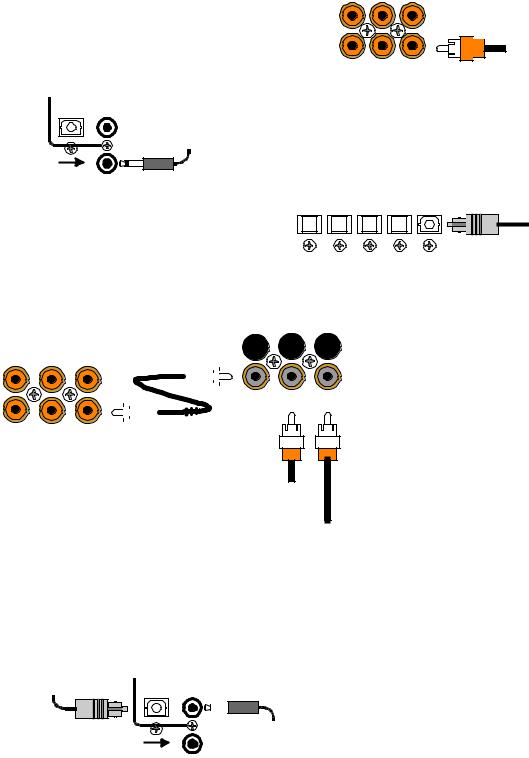
DIGITAL CONNECTIONS
Connect digital inputs (DVD, VLD, etc.) to the A/V System Controller. You will need either coaxial or optical digital inputs to play Dolby Digital (AC-3) or DTS surround sound processing. Digital connections are also recommended for PCM sources. If your source has both optical and coaxial outputs connect only one.
COAX DIGITAL INPUTS
TV-V3 V2 V1
Coaxial digital inputs - standard RCA type connectors. Attach one end of your digital coaxial cable to your source coaxial digital out and the other end to the appropriate A/V System Controller coaxial digital (orange) input.
 Coax digital input
from DVD output
S A T C D DV D/ VLD
DIGITAL OUTPUTS 3.5mm OPTICAL COAX
V3
3.5mm COAX INPUT
3.5 mm digital input from PC or portable
3.5mm
coaxial digital input - You may connect the V3 coaxial input using a 3.5 mm mono jack instead of the RCA type jack. This input works the same as the other digital inputs but uses a 3.5 mm mono jack instead of an RCA. The plug must be wired as tip (+) and the long barrel section (-).
Optical digital inputs - First, remove the cap on the optical digital input. Save the cap. Attach one end of your digital optical cable to your source and the other end to the appropriate digital input on the back of the A/V System Controller.
|
OPTICAL DIGITAL INPUTS |
|
||
SAT |
CD |
DVD |
V2 |
V1 |
Optical digital output from source
Receiver
COAX DIGITAL INPUTS
TV-V3 |
V2 |
V1 |
|
|||
|
|
|
|
|
|
|
|
|
|
|
|
|
|
|
|
|
|
|
|
|
|
|
|
|
|
|
|
|
|
|
|
|
|
|
|
|
|
|
|
|
|
SAT C D DVD/VLD
DT-1
|
|
|
|
|
|
|
|
|
|
|
|
|
|
|
|
|
|
|
|
|
|
|
|
|
|
|
|
|
|
|
|
|
|
|
|
|
|
|
|
|
|
|
|
|
|
|
|
|
|
|
|
|
|
|
MAIN |
C O A X |
AC-3 RF |
||
|
|
|
|
|
O U T P U T |
INPUT |
|
INPUT |
|
|
|
|
|
|
|
|
|
|
|
|
|
|
|
|
|
|
|
|
|
Coax digital input from VLD output
AC-3 RF input from VLD output
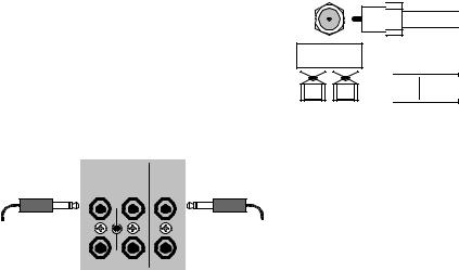
Connecting A Laserdisc Player - Dolby Digital (AC-3) laserdiscs use a special technique called AC-3 RF to encode the Dolby Digital bitstream. If the laserdisc player is capable of playing back Dolby Digital discs it will have a separate output for this bitstream in addition to the normal coaxial and/or optical outputs. Do not connect the AC3-RF output directly to your A/V System Controller. The AC-3 RF bitstream must first be converted to a normal (non-RF) Dolby Digital type signal. It is recommended that a B&K DT-1 be used to convert and select between the Laser’s AC-3 RF and PCM/DTS signals. The output from a DT-1 will automatically select between the connected PCM/DTS bitstreams and the converted AC-3 RF Dolby Digital signal. Other AC-3 RF to Dolby Digital decoders may not make this switch automatically.
Connect the laserdisc’s AC3-RF output to the DT-1’s AC-3 RF input. Connect either the laserdisc player’s PCM coaxial or optical digital output (not both) to the DT-1’s coaxial or optical input. Connect the DT-1’s coaxial output to the desired coaxial digital input on your A/V System Controller.
|
|
|
|
Digital Outputs - Connect to a digital recorder (CD-R, |
||||
|
|
|
|
minidisc, DAT, personal computer, etc.) This signal is |
||||
|
|
|
|
the same as the incoming digital signal from the |
||||
|
|
|
|
selected source. If your digital recorder has both |
||||
|
|
|
|
optical and coaxial inputs you need only connect one. |
||||
Optical digital output |
DIGITAL OUTPUTS |
|
The A/V System Controller converts optical to coaxial |
|||||
3.5mm |
|
|||||||
to digital recorder |
|
|
and coaxial to optical. You can connect one digital |
|||||
|
OPTICAL COAX |
|
||||||
|
|
|
|
recorder to the optical output and another recorder to |
||||
|
|
|
3.5 mm digital output |
the coaxial. The coaxial connector is a 3.5 mm type for |
||||
|
|
V3 |
direct |
connection |
to |
a personal |
computer. You will |
|
|
|
to digital recorder |
||||||
|
3.5mm |
need |
an adapter |
to |
connect the |
3.5mm type to a |
||
COAX INPUT |
|
|||||||
standard RCA type coaxial input
12 |
p/n 12698 Rev. 9808B |
|

SURROUND OUTPUT CONNECTIONS
Connect the A/V System Controller’s surround outputs to your external amplifier(s) or powered speakers.
Here is a typical A/V System Controller output setup:
P O W E R E D S U B W O O F E R
|
SURROUND OUTPUTS |
SUB 1 |
CENTER 1 REAR L FRONT L |
SUB 2 |
CENTER 2 REAR R FRONT R |
INPUT 1 |
INPUT 2 |
INPUT 3 |
INPUT 4 |
INPUT 5 |
|||||
|
|
|
|
Power Amplifier |
|
|
|
|
|
OUTPU T 1 |
OUTPU T 2 |
OUTPU T 3 |
OUTPU T 4 |
OUTPU T 5 |
|||||
MINUS |
P L U S |
MINUS |
P L U S |
MINUS |
P L U S |
MINUS |
P L U S |
MINUS |
P L U S |
|
|
|
|
|
|
|
|
|
|
Rear Left |
Rear Right |
Center |
Front Right |
Front Left |
Subwoofer Output - Connect an RCA cable from one of the A/V System Controller’s two SUB outputs (part of the surround outputs). You may connect a second subwoofer to the other SUB output if desired. If your subwoofer does not contain its own amplifier you will need to purchase an external B&K or other power amplifier. Connect the A/V System Controller’s SUB output to the audio input of the external amplifier. Connect the external amplifier’s speaker output to your subwoofer.
13 |
p/n 12698 Rev. 9808B |
|
ANTENNA CONNECTIONS
The FM jack is a standard screw on F-type connector. The AM is a push type. Strip ¼ inch of insulation off your AM antenna wires and insert one wire end into each hole while holding the tabs down. Release the tabs to lock in the AM antenna wires.
T U N E R
FM antenna
FM Antenna Input

 from Indoor/Outdoor Antenna,
Cable Box, etc.
 AM Antenna Input
 from Loop Antenna
AM antenna
CONTROL OUTPUTS / IR INPUTS
CONTRO L OUT |
IR IN |
|
|
1 |
2 |
Z1 |
CAUTION! |
+12VDC |
|
||
|
50mA |
|
|
3.5 mm control output |
|
|
3.5 mm IR in |
to amplifier, etc. |
|
|
from remote repeater |
3 |
4 |
Z2 |
|
Control Outputs - These connections are used for controlling other equipment such as an external B&K Components, Ltd. amplifier, projection screen, etc. Connect your control cable to the A/V System Controller using a mono 3.5 mm jack shown at left. The plug must be wired as tip (+) and the long barrel section (-).
The Control outputs are programmable for each source in your system (see “Advanced Setup”). However, the A/V System Controller provides the following factory preprogrammed setup that should serve for most standard system applications.
Control 1 - HEADPHONE - On (+12 VDC) when zone 1 is on and not in Headphone mode, off when zone 1 is off or in Headphone Mode. This mode may be used for controlling external amplifiers or powered subwoofers in zone 1.
Control 2 - ZONE 2. On (+12 VDC) when zone 2 is on, off (0 VDC) when zone 2 is off. This mode is used for controlling external amplifiers, projection screens, etc. in zone 2.
Control 3 - Z1 + Z2. On (+12 VDC) when zone 1, zone 2, or both zones are turned on. Off (0 VDC) when both zones are off.
Control 4 -REMOTE. It will repeat a received 38 kHz modulated IR signal. The A/V System Controller will transmit received IR signals even in sleep mode.
Note - The control outputs can output a maximum of 50 mA. Check to see that the source you are connecting to the control out requires 50 mA or less current.
WARNING - Not all manufacturers adhere to the +12 VDC control specification. Check to see if your sources control inputs are +12 VDC compatible. Do not connect your A/V System Controller’s control outputs to a source with control or remote inputs rated at +5 VDC or other voltage rating. Damage to your source may result.
IR Inputs - Your A/V System Controller can be controlled by a directly connected IR repeater system in combination with or in place of the supplied remote control. Connect your IR input cable to the A/V System Controller using a mono 3.5 mm jack shown above. The plug must be wired as tip (+) and the long barrel section (-). The inputs are standard 38kHz modulated IR type with a voltage range of +5 to +12 VDC.
14 |
p/n 12698 Rev. 9808B |
|
 Loading...