

baltur Minicomist 7, Minicomist 11 User Manual

EN
Manual
instructions for use
TR
Kullanım
talimatları kılavuzu.
MINICOMIST 7
MINICOMIST 11
ORIGINAL INSTRUCTIONS ARE (IT)
ORİJİNAL KULLANIM KILAVUZU (IT)
0006081159_201102


- Before using the burner for the rst time please carefully read the chapter “WARNINGS NOTES FOR THE USER : HOW TO USE
THE BURNER SAFELY” in this instruction manual, which is an integral and essential part of the product. The works on the burner
and on the esystem have to be carried out only by competent people.
- Read carefully the instructions before starting the burner and service it.
E
N
- The system electric feeding must be disconnected before starting working on it.
- If the works are not carried out correctly it is possible to cause dangerous accidents.
- Brülörü ilk defa kullanmadan önce lütfen ürünün bütünleşik ve lüzumlu bir parçası olarak brülörle beraber verilen bu kullanma kılavuzu
içinde yer alan “BRÜLÖRÜN GÜVENLE KULLANILMASI İÇİN KULLANICIYA UYARI NOTLARI” bölümünü dikkatle okuyunuz. Brülör
ve sistem üzerindeki çalışmalar sadece yetkili personel tarafından yapılmalıdır.
- Brülörü çalıştırmadan veya onarımına başlamadan önce kullanma kılavuzunu dikkatle okuyunuz.
- Brülör üzerinde onarıma başlamadan önce sistemin elektrik beslemesi kesilmelidir.
- Talimatlara titizlikle uyulmayıp, çalışmalar düzgün yürütülmediği tehlikeli kazaların oluşması mümkündür.
G
L
I
S
H
T
ü
r
k
ç
e
0006081159_201102

E
BALTUR S.p.A.
Via Ferrarese 10 - 44042 CENTO (Ferrara) ITALIA
Tel. 051.684.37.11 Fax 051.685.75.27/28
(International Tel. ++39.051.684.37.11 - Fax ++39.051.683.06.86)
http://www.baltur.it - http://www.baltur.com - E-MAIL info@baltur.it
Declaration of Conformity
N
G
L
S
H
We declare that our products
BPM...; BGN…; BT…; BTG…; BTL…; TBML...; Comist…;
GI…; GI…Mist; Minicomist…; PYR…; RiNOx…; Spark...;
Sparkgas...; TBG...;TBL...; TBML ...; TS…; IBR...; IB...
(Variant: … LX, for low NOx emissions)
I
Description:
forced air burners of liquid, gaseous and mixed fuels for residential and
industrial use meet the minimum requirements of the European Directives:
90/396/CEE ...............................................(D.A.G.)
89/336/CEE - 2004/108/CE ........................(C.E.M.)
73/23/CEE – 2006/95/CE ...........................(D.B.T.)
2006/42/CEE .............................................(D.M.)
and conform to European Standards:
UNI EN 676:2008 (gas and combination, gas side)
UNI EN 267:2002 (diesel and combination, diesel side)
These products are therefore marked:
0085
Dr. Riccardo Fava
04/01/2010
i
!
Important / note
Indice analitico
COMBINED DUNGS GAS VALVE ...............................................................................................................................................17
CHECKS PRIOR LIGHT OIL FIRING - DUAL FUEL BURNER’S FIRING INDICATION - ELECTRICAL CONNECTIONS ........11
FITTING THE BURNER TO THE BOILER AND CONNECTING THE GAS PIPE ........................................................................9
GAS BURNER CONTROL DEVICE GAS LME 22.. .....................................................................................................................15
MAINTENANCE ...........................................................................................................................................................................12
NOTES ON USE OF PROPANE (L.P.G.) .....................................................................................................................................13
STARTING UP AND REGULATION WITH LIGHT OIL - STARTING UP AND REGULATION WITHMETHANE GAS .................12
TECHNICAL DATA AND OVERALL DIMENSIONS ......................................................................................................................7
ELECTRIC DIAGRAM ...................................................................................................................................................................34
Information
Managing Director / CEO
I
Warning / Attention
4 / 18
0006081159_201102
I
accordance with current regulations and in any case suf cient to ensure
ventilation openings for the room where a burner or a boiler is installed
• If it is decided not to use the burner any more, the following actions must
• Check that the person who carried out the installation of the burner xed
b) Adjust the combustion air ow to obtain combustion yield of at least
• If the burner repeatedly stops in lock-out, do not keep trying to manually
WARNING NOTES FOR THE USER HOW TO USE THE BURNER SAFELY
FOREWORD
These warning notes are aimed at ensuring the safe use of the components of heating systems for civil use and the production of hot water.
They indicate how to act to avoid the essential safety of the components
being compromised by incorrect or erroneous installation and by improper
or unreasonable use. The warning notes provided in this guide also seek
to make the consumer more aware of safety problems in general, using
necessarily technical but easily understood language. The manufacturer
is not liable contractually or extra contractually for any damage caused
by errors in installation and in use, or where there has been any failure to
follow the manufacturer’s instructions.
GENERAL WARNING NOTES
• The instruction booklet is an integral and essential part of the product
and must be given to the user. Carefully read the warnings in the booklet as they contain important information regarding safe installation,
use and maintenance. Keep the booklet to hand for consultation when
needed.
• Equipment must be installed in accordance with current regulations,
with the manufacturer’s instructions and by quali ed technicians. By
the term ‘quali ed technicians’ is meant persons that are competent in
the eld of heating components for civil use and for the production of
hot water and, in particular, assistance centres authorised by the manufacturer. Incorrect installation may cause damage or injury to persons,
animals or things. The manufacturer will not in such cases be liable.
• After removing all the packaging make sure the contents are complete
and intact. If in doubt do not use the equipment and return it to the
supplier. The packaging materials (wooden crates, nails, staples, plastic
bags, expanded polystyrene, etc.) must not be left within reach of children as they may be dangerous to them. They should also be collected
and disposed on in suitably prepared places so that they do no pollute
the environment.
• Before carrying out any cleaning or maintenance, switch off the equipment at the mains supply, using the system’s switch or shut-off systems.
• If there is any fault or if the equipment is not working properly, de-activate the equipment and do not attempt to repair it or tamper with it
directly. In such case get in touch with only quali ed technicians. Any
product repairs must only be carried out by BALTUR authorised assistance centres using only original spare parts. Failure to act as above
may jeopardise the safety of the equipment. To ensure the ef ciency
and correct working of the equipment, it is essential to have periodic
maintenance carried out by quali ed technicians following the manufacturer’s instructions.
• If the equipment is sold or transferred to another owner or if the owner
moves and leaves the equipment, make sure that the booklet always
goes with the equipment so it can be consulted by the new owner and/
or installer.
• For all equipment with optionals or kits (including electrical), only original accessories must be used.
BURNERS
• This equipment must be used only for its expressly stated use: applied
to boilers, hot air boilers, ovens or other similar equipment and not
exposed to atmospheric agents. Any other use must be regarded as
improper use and hence dangerous.
• The burner must be installed in a suitable room that has ventilation in
correct combustion
• Do not obstruct or reduce the size of the burner’ air intake grills or the
or dangerous mixtures of toxic and explosive gases may form.
• Before connecting the burner check that the details on the plate correspond to those of the utility supplies (electricity, gas, light oil or other
fuel).
• Do not touch hot parts of the burner. These, normally in the areas near
to the ame and any fuel pre-heating system, become hot when the
equipment is working and stay hot for some time after the burner has
stopped.
be performed by quali ed technicians:
a) Switch off the electrical supply by disconnecting the power cable from
the master switch.
b) Cut off the fuel supply using the shut-off valve and remove the control
wheels from their position.
c) Render harmless any potentially dangerous parts.
Special warning notes
it securely to the heat generator so that the ame is generated inside
the combustion chamber of the generator itself.
• Before starting up the burner, and at least once a year, have quali ed
technicians perform the following operations:
a) Set the burner fuel capacity to the power required by the heat ge-
nerator.
the minimum set by current regulations.
c) Carry out a check on combustion to ensure the production of no-
xious or polluting unburnt gases does not exceed limits permitted
by current regulations.
d) Check the adjustment and safety devices are working properly.
e) Check the ef ciency of the combustion products exhaust duct.
f) Check at the end of the adjustments that all the adjustment devices
mechanical securing systems are properly tightened.
g) Make sure that the use and maintenance manual for the burner is
in the boiler room.
reset but call a quali ed technicians to sort out the problem.
• The running and maintenance of the equipment must only be carried
out by quali ed technicians, in compliance with current regulations.
E
N
G
L
I
S
H
5 / 18
0006081159_201102
E
equipment or dangerous situations may arise with the build up of toxic
It should be pointed out that high ef ciency boilers and similar discharge
In the above situation, traditional ues (in terms of their diameter and heat
insulation) may be suitable because the signi cant cooling of the combustion
products in these permits temperatures to fall even below the condensation
point. In a ue that works with condensation there is soot at the point the
exhaust reaches the atmosphere when burning light oil or heavy oil or the
presence of condensate water along the ue itself when gas is being burnt
(methane, LPG, etc.). Flues connected to high ef ciency boilers and similar
must therefore be of a size (section and heat insulation) for the speci c use
I
WARNING NOTES FOR THE USER HOW TO USE THE BURNER SAFELY
ELECTRICAL SUPPLY
N
• The equipment is electrically safe only when it is correctly connected to an
G
L
S
H
ef cient ground connection carried out in accordance with current safety
regulations. It is necessary to check this essential safety requirement.
If in doubt, call for a careful electrical check by a quali ed technicians,
since the manufacturer will not be liable for any damage caused by a
poor ground connection.
I
• Have quali ed technicians check that the wiring is suitable for the
maximum power absorption of the equipment, as indicated in the technical
plate, making sure in particular that the diameter of cables is suf cient
for the equipment’s power absorption.
• Adapters, multiple plugs and extension cables may not be used for the
equipment’s power supply.
• An ominpolar switch in accordance with current safety regulations is
required for the mains supply connection.
• The electrical supply to the burner must have neutral to ground
connection. If the ionisation current has control with neutral not to ground
it is essential to make a connection between terminal 2 (neutral) and the
ground for the RC circuit.
• The use of any components that use electricity means that certain
fundamental rules have to followed, including the following:
- do not touch the equipment with parts of the body that are wet or damp
or with damp feet
- do not pull on electrical cables
- do not leave the equipment exposed to atmospheric agents (such as
rain or sun etc.) unless there is express provision for this.
- do not allow the equipment to be used by children or inexpert
persons.
• The power supply cable for the equipment not must be replaced by the
user. If the cable gets damaged, switch off the equipment, and call only
on quali ed technicians for its replacement.
• If you decide not to use the equipment for a while it is advisable to switch
off the electrical power supply to all components in the system that use
electricity (pumps, burner, etc.).
GAS, LIGHT OIL, OR OTHER FUEL SUPPLIES
General warning notes
• Installation of the burner must be carried out by quali ed technicians
and in compliance with current law and regulations, since incorrect
installation may cause damage to person, animals or things, for which
damage the manufacturer shall not can be held responsible.
• Before installation it is advisable to carry out careful internal cleaning
of all tubing for the fuel feed system to remove any residues that could
jeopardise the proper working of the burner.
• For rst start up of the equipment have quali ed technicians carry out
the following checks:
• If you decide not to use the burner for a while, close the tap or taps that
supply the fuel.
Special warning notes when using gas
• Have quali ed technicians check the following:
a) that the feed line and the train comply with current law and
regulations.
b) that all the gas connections are properly sealed.
• Do not use the gas pipes to ground electrical equipment.
• Do not leave the equipment on when it is not in use and always close
the gas tap.
• If the user of is away for some time, close the main gas feed tap to the
burner.
• If you smell gas:
a) do not use any electrical switches, the telephone or any other object
that could produce a spark;
b) immediately open doors and windows to create a current of air that
will purify the room;
c) close the gas taps;
d) ask for the help of quali ed technicians.
• Do not block ventilation openings in the room where there is gas
and explosive mixtures.
FLUES FOR HIGH EFFICIENCY BOILERS AND SIMILAR
combustion products (fumes) at relatively low temperatures into the ue.
to avoid such problems as those described above.
6 / 18
0006081159_201102
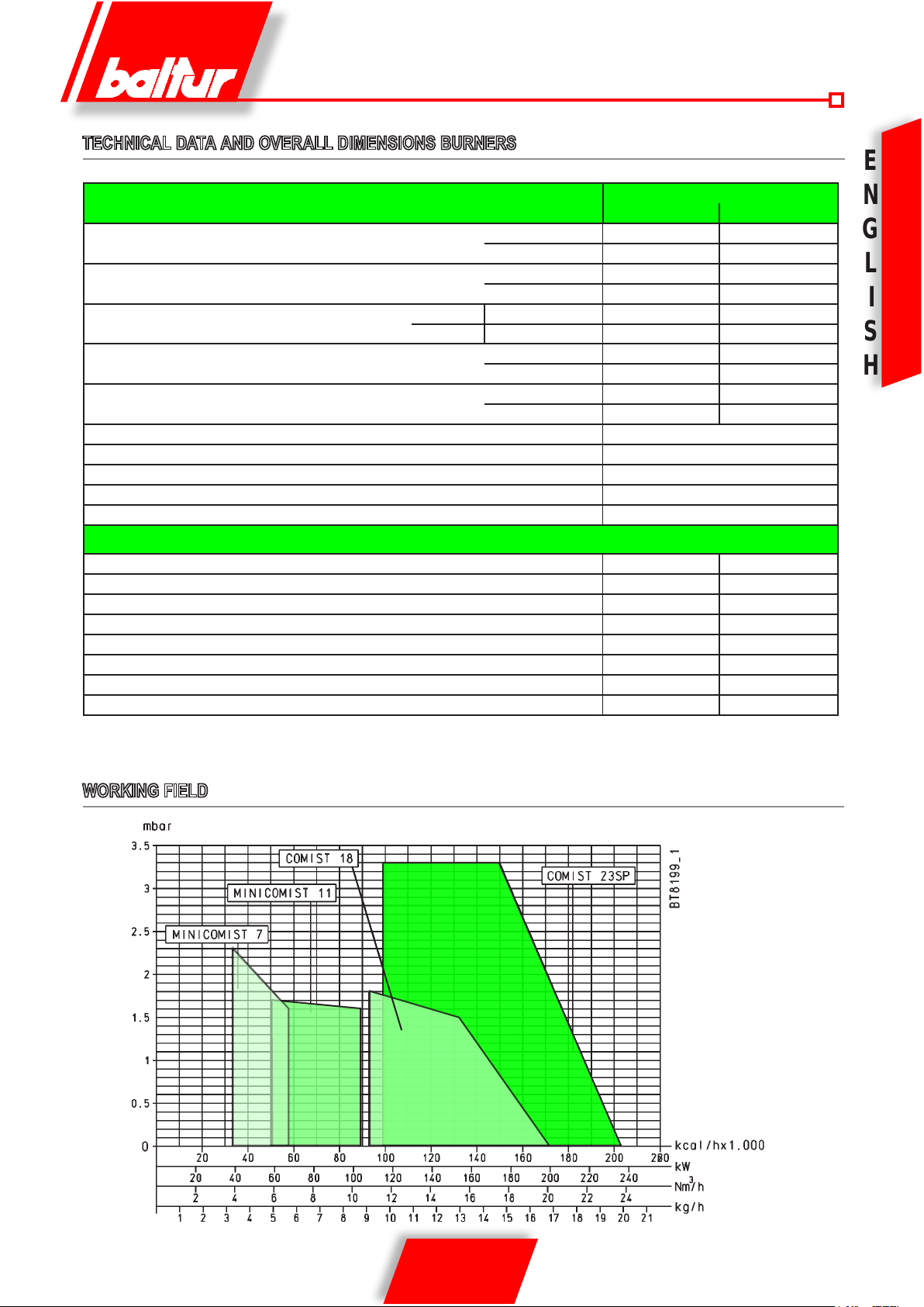
TECHNICAL DATA AND OVERALL DIMENSIONS BURNERS
E
MOD.
MINICOMIST 7 MINICOMIST 11
BURNER OUTPUT
FLOW RATE
PRESSURE In order to obtain the maximum ow rate
FLOW RATE
BURNER OUTPUT
VISCOSITY Light oil 1,5°E a 20°C
VOLTAGE 50Hz Volt 1~ 230V
FAN MOTOR 50Hz kW 0,13 - 2800 r.p.m.
PUMP MOTOR 50Hz kW 0,075 - 2780 r.p.m.
IGNITION TRANSFORMER 50Hz 8 kV - 20 mA
STANDARD ACCESSORIES
BURNER FIXING FLANGE N° 1 N° 1
INSULATING GASKET N° 1 N° 1
INSULATING CORD N° 1 N° 1
FILTER N°1 - 3/8” N°1 - 3/8”
FLEXIBLE PIPE N°2 - 1/4” x 3/8” N°2 - 1/4” x 3/8”
STUD BOLTS N°4 M8 N°4 M8
EXAGONAL NUTS N°4 M8 N°4 M8
FLAT WASHERS N°4 Ø8 N°4 Ø8
CE MIN mbar 20 20
UNI-CIG MIN mbar 12 20
MIN kW 38,5 58,4
MAX kW 66,8 103
MIN m³/h 3,9 5,9
MAX m³/h 6,7 10,4
MIN kg/h 3,3 4,9
MAX kg/h 5,7 8,7
MIN kW 38,5 58,4
MAX kW 66,8 103
N
G
L
I
S
H
WORKING FIELD
7 / 18
0006081159_201102
E
N
G
L
S
H
I
0002570110
MOD. A A1 A2 B B1 B2 C D
minD maxE ØG ØL minL maxM Ø
MINICOMIST 7 510 300 210 510 205 305 510 40 156 95 3/4” 130 155 M8 115
MINICOMIST 11 510 300 210 510 205 305 510 40 156 95 3/4” 130 155 M8 115
N
COMPONENTS LIST
1 - Ignition transformer
2 - Light oil electrovalve
3 - Pump
4 - Pump motor
5 - Air pressure switch
6 - Air regulation sector
7 - Fan motor
8 - Gas/light oil switch
9 - Terminal board box
10 - Electric panel
11 - Reset button
12 - Flame detector
13 - Combustion head
14 - Insulating gasket
15 - Sliding ange
16 - Flame disc regulation screw
17 - Monoblock gas valve
8 / 18
0006081159_201102
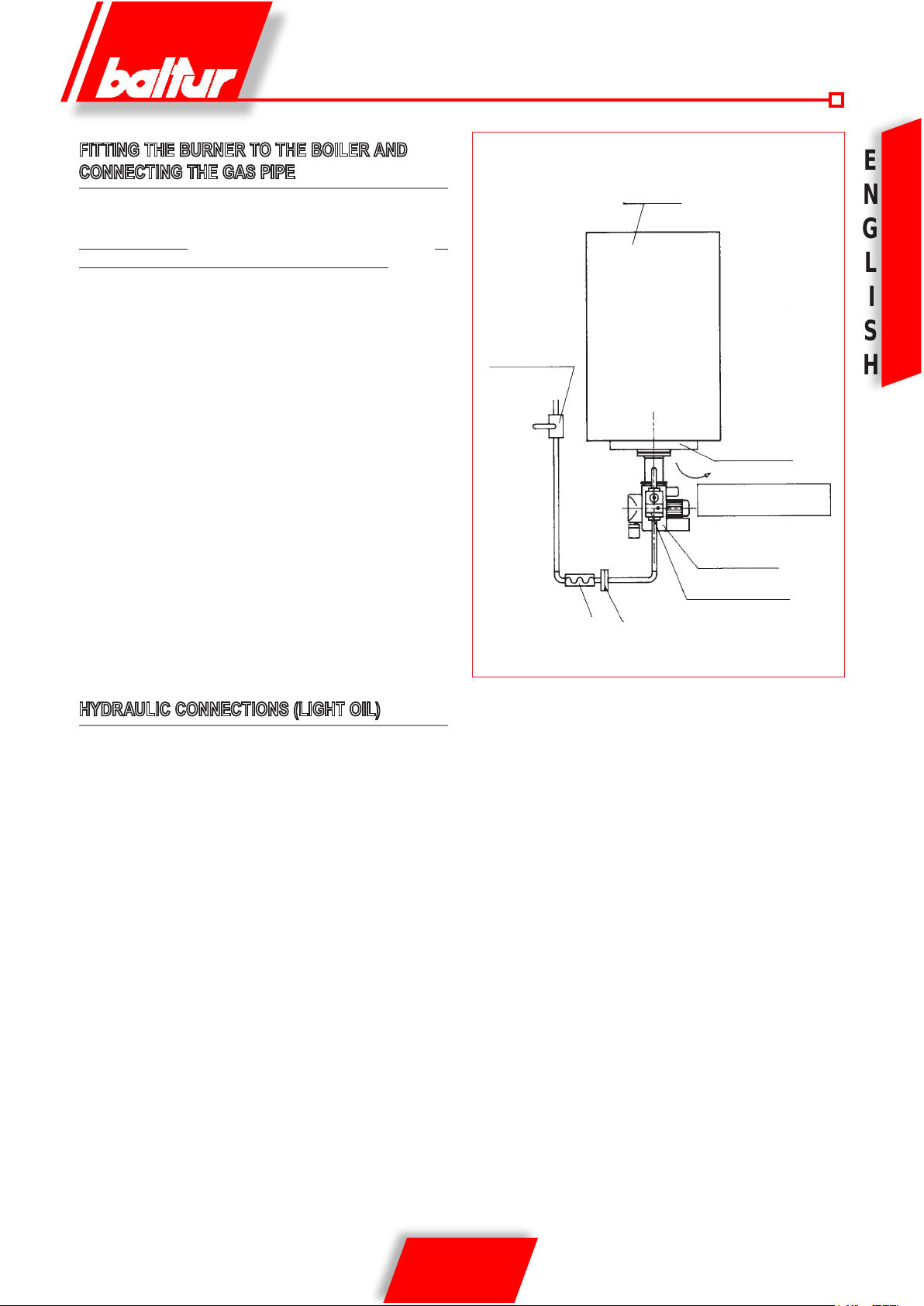
FITTING THE BURNER TO THE BOILER AND
CONNECTING THE GAS PIPE
The burner is tted with a sliding attachment ange on the burner
head. When tting the burner to the boiler, this ange must be
correctly positioned is that the burner head penetrates the boiler by
the amount specied by the manufacturers of the boiler.
When the burner is tted correctly to the boiler, proceed whit the
connection of the gas feed pipe (see
BT 8780 and BT 1387).
The size of the gas feed pipe must be proportional to its length and
to the gas delivery rate in accordance with the UNI standard (see
diagram), and it must be perfectly airtight and properly tested before
running the initial tests on the burner.
It is essential to t a connector to this pipe, near to the burner, for the
easy dismounting of the burner and/or the opening of the boiler door.
FOR BURNERS WITH DUNGS GAS VALVE mod. MB.....
GATE
UPPER VIEW
BOILER
E
N
G
L
I
S
H
DOOR
The DUNGS mod. MB.... valve has a lter and gas pressure sta-
biliser, which means that only the cut-off cock and the vibration
damper joint should be tted to the gas feed pipe. A pressure
reduction unit should be installed outside the heating system only
in cases where the gas pressure exceeds the level permitted by
the standard (400 mm.C.A.).
It is recommended to put a bend directly on the burner gas train
before tting the detachable connector. This is to allow the opening
of the boiler door, when the connector itself has been opened.
These details are clearly illustrated in the following diagram.
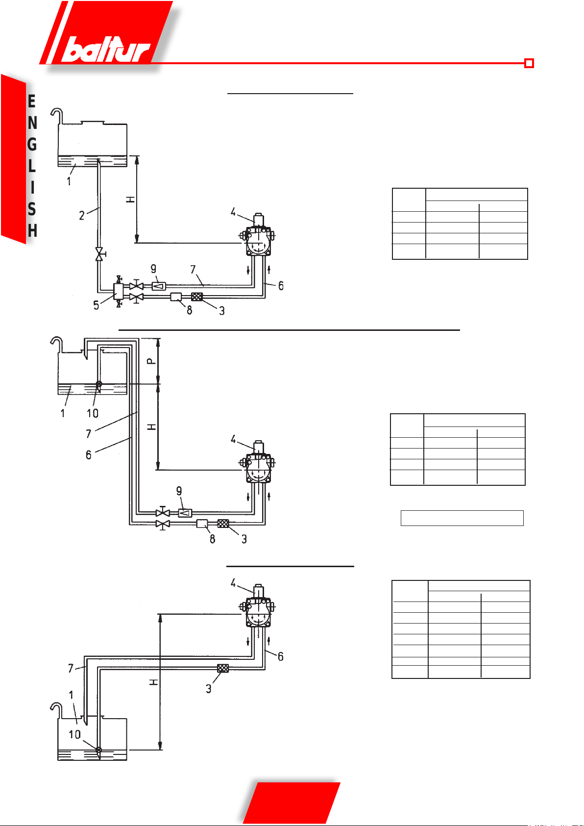
HYDRAULIC CONNECTIONS (LIGHT OIL)
The connection pipes between tank and burner must be completely tight. We suggest to use copper or steel pipes of an adequate
diameter (see list and drawing).
At the rigid pipes ands it must be tted the fuel’s detection gates.
Filters, exible pipes and relative connection couplings are supplied
along with burner. Pump is equipped with suitable connecting points
(see drawing) for detection instruments (pressure gauge and vacuummeter). Pressure drop in suction must not exceed 4,6 mm.W.G.
= to 35 cm.Hg. for a proper and silent operation. Probable max.
pressure on suction and on the return 1,5 bar.
ANTI-VIBRATION
JOINT
DOOR OPENING
A DIRECTION
BURNER
MULTIBLOC VALVE
PIPE FITTING
9 / 18
0006081159_201102
E
N
G
L
GRAVITY FEED SYSTEM
1 Tank
2 Feeding pipe
3 Wire-net lter
4 Pump
5 Degasier
6 Suction pipe
7 Return pipe
8 Automatic fuel interception
device at burner shut off
9 Non-return valve
S
H
I
Pump axis
H Total lenght meters
meters Ø i = 10 mm Øi.= 12 mm
1 20 30
2 25 35
3 30 40
4 35 45
SIPHON FEED SYSTEM WITH FEED FROM THE TOP OF THE TANK
1 Tank
3 Wire-net lter
4 Pump
6 Suction pipe
7 Return pipe
Pump axis
8 Automatic fuel interception
device at burner shut off
9 One-way valve
10 Bottom valve
H Total lenght meters
meters Ø i = 10 mm Øi.= 12 mm
1 20 30
2 25 35
3 30 40
4 35 45
Pump axis
Dimension P = 3,5 m. (max.)
SUCTION FEED SYSTEM
1 Tank
3 Wire-net lter
4 Pump
6 Suction pipe
7 Return pipe
10 Bottom valve
N.B. Comply with existing regulations regarding apparatus
required in the pipeline system
H - Height difference between minimum fuel tank level and pump axis.
L - Total length of pipeline, including vertical lenght. Subtract 0,25 mt.
for every elbow or gate valve.
10 / 18
0006081159_201102
H Total lenght meters
meters Ø = 10mm Øi. 12 mm
0,5 15 27
1 12 23
1,5 9 19
2 7 15
2,5 4 10
3 - 7
3,5 - -
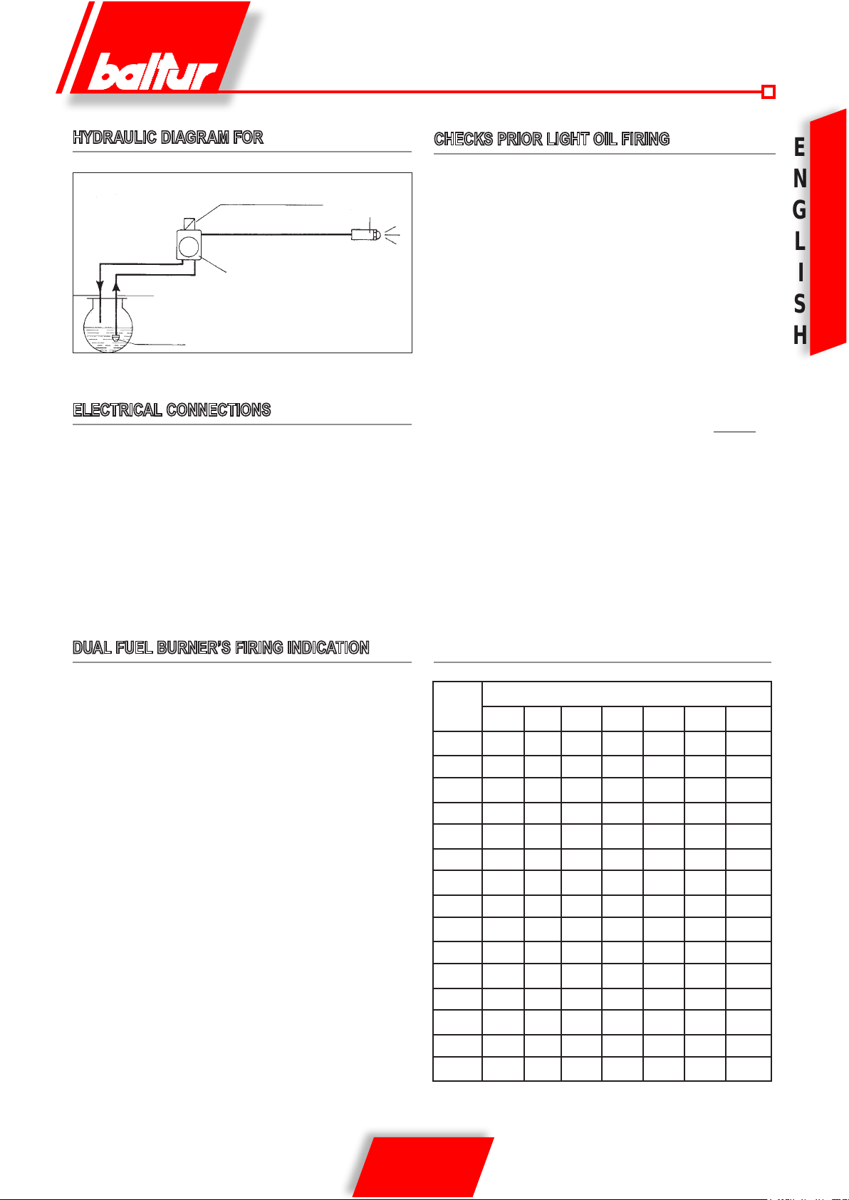
HYDRAULIC DIAGRAM FOR
Return
Suction
Light oil electrovalve
Light oil pump
(12 bar pressure)
Foot valve
Nozzle
ELECTRICAL CONNECTIONS
Electric lines should be at an adequate distance from
hot parts. Make sure that all electrical connections are
made with ex electric wire, with suitable size for the
voltage and absorbed power.
Maximum current absorbed = 600 VA
Minimum section of the feed line = 1mm2 with 230V.
For the LGB 22 control box, the intensity of the cell
current should be between 200 microamperes and 500
microamperes.
CHECKS PRIOR LIGHT OIL FIRING
Make sure that the nozzle with sprouting angle at 60° is suitable to
the boiler’s capacity.
In the list hereunder you nd the delivery values in kg/h of light oil
related to the nozzle’s size and to the pump’s pressure (normally
12 bar). (Please note that 1 light oil kg corresponds to 10.200
kcal about).
Make sure that the protrusion of the combustion head inside
the combustion chamber is according to boiler manufacturer’s
instructions.
Make sure that the return pipe in tank has no obstructions, such as
gates closed caps etc.
8502cmt18.tif
Probable obstructions could cause faults on the pump’s shaft or
ex pipe.
Open slightly the air purge device of the pump.
Disconnect the wire number 39 which feeds the pump motor from
the terminal on the contactor “K1” and connect it from moment the
terminal “K1.56” of the “input junction box” so as to feed directly
the pump motor.
Now close the reverser-switch on the burner and the general one
and make sure that the rotation sense is correct. Thus the pump
motor is connected and starts the pump witch sucks the light oil.
When the light oil ow the air purge device open the main switch
so as to stop the motor.
Be set original connections to the corresponding terminals.
The burner is thus ready to operate at light oil.
E
N
G
L
I
S
H
DUAL FUEL BURNER’S FIRING INDICATION
We suggest to start the burner with the liquid fuel, as in this case
the delivery is bound to the nozzle size whilst the gas delivery can
be easily changed by acting on the relative capacity adjuster.
If the burner is in the automatic version, the selector for the fuel
change connects a cyclic relay which inserts, tanks to an auxiliary
relay, components for the use of both fuels (valves, pressure
switches, pump etc.).
After having changed the position of the selector from gas to light oil
and voiceovers, it occurs to leave it stopped for at least 10 seconds
which is the time the cyclic relay needs to carry out its program.
ATTENTION
If the selector is moved from a position to another before the period
of 10 seconds, the cyclic relay stops in the middle of its program not
allowing to use the burner both with gas and with light oil.
TABLE OF NOZZLE DELIVERY RATES IN Kg/h OF LIGHT
OIL
Nozzle
G.P.H.
0,60 2,04 2,16 2,28 2,39 2,50 2,60 2,70
0,65 2,21 2,34 2,47 2,59 2,71 2,82 2,92
0,75 2,55 2,70 2,85 2,99 3,12 3,25 3,37
0,85 2,89 3,06 3,23 3,39 3,54 3,68 3,82
1,00 3,40 3,61 3,80 3,99 4,16 4,33 4,50
1,10 3,74 3,97 4,18 4,38 4,58 4,77 4,95
1,20 4,08 4,33 4,56 4,78 5,00 5,20 5,40
1,25 4,25 4,50 4,75 5,00 5,20 5,40 5,60
1,35 4,59 4,87 5,13 5,38 5,62 5,85 6,07
1,50 5,10 5,41 5,70 5,90 6,24 6,50 6,75
1,65 5,61 5,95 6,27 6,58 6,87 7,15 7,42
1,75 5,95 6,31 6,65 6,98 7,29 7,58 7,87
2,00 6,80 7,21 7,60 7,97 8,33 8,67 8,99
2,25 7,65 8,15 8,55 8,97 9,37 9,75 10,12
8 9 10 11 12 13 14
Pump pressure bar
2,50 8,50 9,01 9,50 9,97 10,41 10,83 11,24
11 / 18
0006081159_201102
STARTING UP AND REGULATION WITH LIGHT
E
OIL
N
1) Check that the pump and fan motors rotate in the right direction.
2) Make sure that the discharge of combustion products can take
G
place freely (chimney lock-gates should be open) and that there
L
I
S
H
is water in the boiler.
3) Open as much as considered necessary, the combustion air
regulator, and open by about half the air passage between
the disk and the head by operating the regulating screw of the
ame disk.
4) Close the main switch and the burner switch in order to connect
the burner and wait for it to start up. The burner is turned on in
this way, and will carry out the pre-ventilation phase. If the air
pressure exceeds the value at which the air pressure switch
has been set, the ignition transformer will be connected and
subsequently the light oil valve will be inserted. With the burner
operating, correct if necessary, the combustion air delivery.
5) The burner is tted with a device which optimises the combustion
by reducing or increasing the air passage between the disk and
the head. Maximum smoke intensity permissible is N° 2 of the
Bacharach scale with a Carbon Dioxide (CO2) value between
10 and 13 %. It is normally necessary to reduce the air passage
between the disk and the head when operating with a reduced
fuel delivery. This passage must be proportionately opened
more when the burner is working with a higher fuel delivery.
This manoeuvre can be carried out by operating the regulating
screw of the ame disk. After having modied the ame disk
position, it is then necessary to verify that ignition occurs
correctly.
4) Give current to the burner by connecting the main switch and
the burner switch. The burner is turned on in this way and will
then carry out the pre-ventilation phase. If the air pressure
exceeds the value at which the air pressure switch has
been set, the ignition transformer will be connected and,
subsequently, the gas valves will be inserted. The safety valve
opens completely while the principle valve, which incorporates
the regulation devices, opens twice. When it opens the rst time,
it realises the starting output immediately. The second time, it
opens gradually and when it is completely open the burner is
operating at the maximum value at which the maximum output
regulator has been set. At rst ignition, successive “shutdowns”
can occur, due to the following reasons:
a) The gas pipeline has not been adequately purged of air
and therefore the quantity of gas is not sufcient to allow
a stable ame.
b) A “shutdown” with flame presence can be caused by
ame instability, due to an incorrect air/gas ratio. This
can be remedied by varying the quantity of air and/or gas
delivered, in order to nd the correct ratio. It could also
be caused by an incorrect distribution of air/gas in the
combustion head. This can be corrected by operating the
regulation device of the combustion head – close more
(by loosening the regulating screw) or open more (by
tightening the regulating screw) the air passage between the
head and the gas diffuser. This can be done by operating
the regulating screw of the ame disk.
5) With the burner on, adapt delivery to the value which
corresponds with the potentiality desired (Methane gas = 8550
kcal/m3), by reading the meter. This output can be modied by
operating the special regulator incorporated in the valve, as
explained above.
STARTING UP AND REGULATION WITHMETHANE
GAS
N.B. Please refer to the last pages where specic instructions are
given with regard to regulating the gas delivery in function
with the type of valve tted on the burner.
In order to proceed with ignition, it is indispensable to carry out a
purge of the air contained in the pipeline and check, if the burner is
three-phase, that the sense of rotation of the motor is correct.
Then proceed as follows:
1) Make sure that the discharge of combustion products can take
place freely (chimney lock-gates should be open) and that there
is water in the boiler.
2) Open, as much as considered necessary, the combustion air
regulator, and open by about one third the air passage between
the head and the disk by operating the regulating screw of the
ame disk.
3) Operate the regulators incorporated in the gas valves in such
a way as to obtain the gas delivery presumed necessary.
N.B. Please refer to the last pages where specic instructions
are given with regard to regulating the gas delivery in
function with the type of valve tted on the burner.
6) Control that combustion occurs correctly by using the
appropriate instruments. The maximum permissible for Carbon
Monoxide (CO) is 0,1%; with a Carbon Dioxide (CO2) value of
between 8 and 10%.
7) After regulation, turn the burner off and on again several times
to check that ignition occurs correctly.
SAFETY CHECKS
After regulation, always check:
1) That the burner stops by “opening” the thermostat and the air
and gas pressure switches;
2) The “shut down” by darkening the photoelectric cell (UV).
To unblock the burner, press the appropriate pushbutton.
MAINTENANCE
At the end of the hea ting season, it is good practice
to clean the gas and light oil filters, the combustion head
(disk, insulators, and nozzles), the combustion air passages and
the photoelectric cell (UV). It is advisable to use wooden or plastic
instruments to clean the nozzle passages. Nozzles should be replaced after 12 months’ use.
12 / 18
0006081159_201102
 Loading...