

baltur COMIST 72 DSPGM, COMIST 180 DSPGM, COMIST 122 DSPGM, COMIST 250 DSPGM, COMIST 300 DSPGM Instruction
- Instruction for burners model
COMIST 72 DSPGM
COMIST 122 DSPGM
en
COMIST 180 DSPGM
COMIST 250 DSPGM
COMIST 300 DSPGM
- The works on the burner and on the system have to
be carried out only by competent people.
- Read carefully the instructions before starting the
burner and service it.
- The system electric feeding must be disconnected
before starting working on it.
- If the works are not carried out correctly it is
possible to cause dangerous accidents.
Edition
2003/11
Cod. 0006080115

Dichiarazione del Costruttore
Dichiariamo che i bruciatori di gas, gasolio, olio combustibile e misti (gas/gasolio oppure gas/olio combustibile)
sono da noi prodotti a regola d’arte in conformità alle Norme CE - CEI - UNI vigenti al momento della costruzione.
• La BAL TUR garantisce la certificazione “CE” sul prodotto solo se il bruciatore viene inst allato con la ramp a
gas “CE” fornita dalla BALTUR e con accessori di linea gas certificati “CE” (forniti su richiesta).
NOTA : la presente dichiarazione non è valida, relativamente alla Norma CE oppure UNI, per i bruciatori di gas e per la
parte gas dei bruciatori misti (gas/gasolio oppure gas/olio combustibile) quando, gli stessi, ci vengono ordinati non
conformi alla Norma CE oppure UNI, perché destinati ad uso speciale, non previsto nelle norme sopra indicate.
Manufacturer’s declaration
We hereby declare that our gas, light oil, heavy oil, and combination (gas/light oil or gas/heavy oil)
burners are manufactured in conformance with current CE, CEI and UNI standards.
• BALTUR guarantees the “CE” certification provided that the burner is coupled to the “CE” gas train supplied
by BAL TUR and the “CE” gas line accessories (on request).
NOTE: this declaration is not valid with regard to EC or UNI Standards for gas burners or the gas p art of
duel-fuel burners (gas/light oil or gas/heavy oil) when such burners have been ordered in non-compliance
with the EC St andard or It alian UNI Standard because they are to be used for special purposes not provided
for in the above-mentioned standards.
Declaración del fabricante
Declaramos que la empresa fabrica los quemadores de gas, gasóleo, fuel y mixtos (gas/gasóleo o
gas/fuel) ajustándose a las Normas CE - CEI - UNI vigentes en el momento de su fabricación.
• La firma “BALTUR” garantiza la certificación “CE” sombre el producto sólo si el quemador viene instalado
con la rampa gas “CE” suministrada por la “BALTUR” misma y con los accesorios de linea gas
certificados “CE” (suministrables a pedido).
NOTA: la presente declaración no tiene validez, respecto a la Norma CE o UNI, para los quemadores de
gas y para la parte de gas de los quemadores mixtos (gas/gasóleo o gas/fuel) cuando, los mismos, se
piden no conformes a la Norma CE o a la norma italiana UNI, porque están destinados a un uso especial,
no previsto en las normas arriba mencionadas.
Déclaration du constructeur
Nous déclarons que les brûleurs à gaz, fioul, fioul lourd et mixtes (gaz/fioul ou gaz/fioul lourd) sont
produits selon les règles de l’art, conformément aux Normes CE – CEI – UNI en vigueur au moment de la
fabrication.
• La BALTUR garantit la certification “CE” seulement si les brûleur sont installé avec les rampes de gaz “CE”
produites par la BALTUR et les accessoires de ligne gaz “CE” (fournis sur demande).
NOTE: la présente déclaration n’est pas valable, correspondante à la Norme CE ou bien UNI, pour les
brûleurs à gaz et pour la partie gaz des brûleurs mixtes (gaz/fioul ou bien gaz/fioul lourd) lorsque, ces
derniers, nous sont commandés sans être conformes à la Norme CE ou bien à la norme italienne UNI, parce
qu’ils sont destinés à une utilisation spéciale qui n’est pas prévue par les normes indiquées ci-dessus.
Herstellererklärung
Wir erklären, dass die Gas-, Heizöl-, Schweröl- und Wechselbrenner (Gas/Heizöl oder Gas/Schweröl)
von uns fachgerecht und in Übereinstimmung mit den zum Zeitpunkt der Fertigung geltenden Normen CE CEI - UNI hergestellt wurden.
• Die “CE”-Zertifizierung der von BALTUR hergestellten Produkte ist nurin Verbindung mit einer von BALTUR
gelieferten CE-Gasarmatur und unter Verwendung von CE-zertifizierten Bauteilen in der Gaszufürhrung gültig.
HINWEIS: Die vorliegende Erklärung im Hinblick auf die EU- oder UNI-Normen ist nicht gültig für
Gasbrenner und für den Gasteil von Wechselbrennern (Gas/Öl oder Gas/Schweröl), wenn solche bei uns
ohne Konformität mit den EU-Normen oder mit der italienischen Norm UNI bestellt werden, weil sie eine für
spezielle Verwendung bestimmt sind, die von den oben genannten Normen nicht vorgesehen ist.
L' Amministratore delegato
Dott. Riccardo Fava
2
CARA TTERISTICHE TECNICHE
Ó
R
TECHNICAL DA T A
CARACTIRÍSTICAS TÉCNICAS
N° 0002570030
Rev.
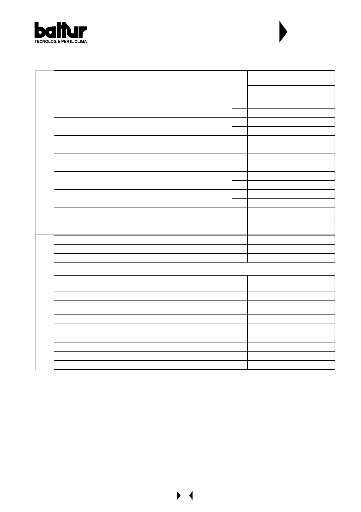
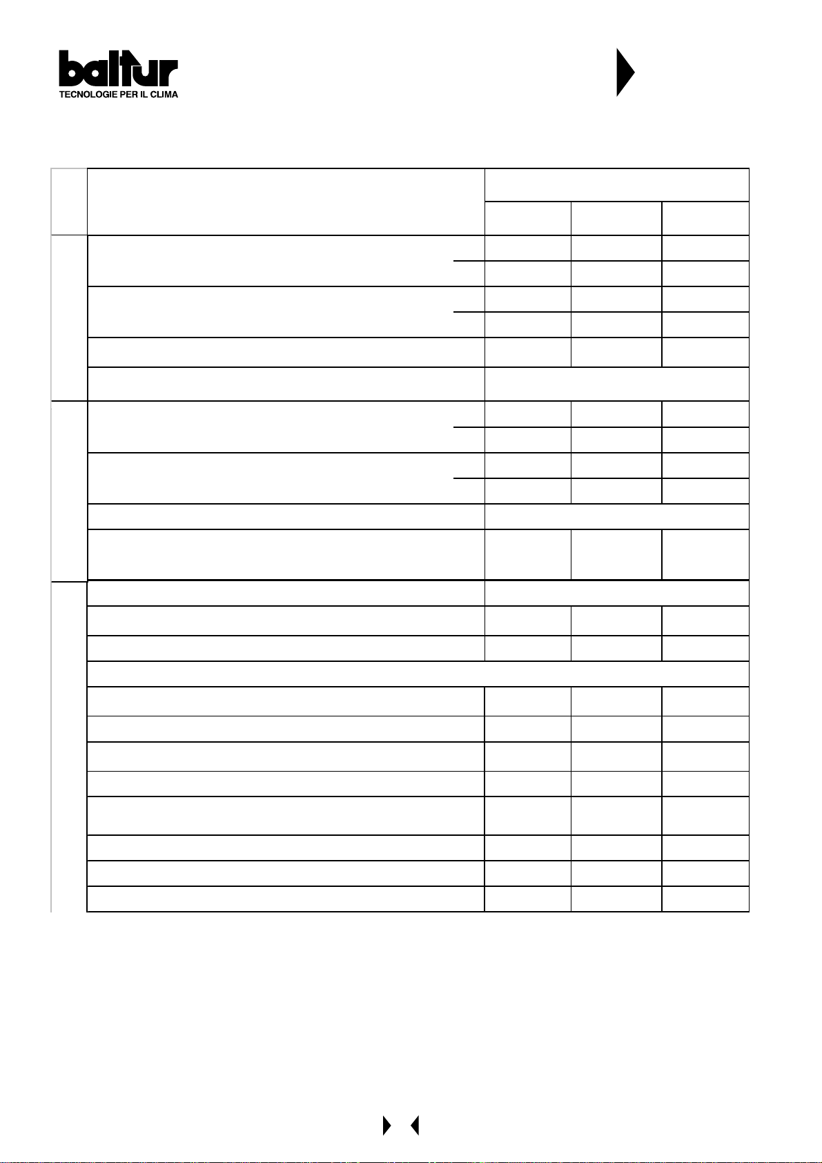
CARATTERIS T I CHE TECNICHE / T ECHNICAL DAT A
CARACTERÍST ICAS T ÉCNICAS / T ECHNIS CHE DAT EN
POTENZA TERMICA / THERMIC CA PACITY /
POTENCIA TÉRMICA / HEIZLEISTUNG
PORTATA / FLOW RA TE / CAUDAL / DURCHSA TZ
PRESSIONE MIN.(*) / MIN. PRESSURE (*) /
PRESIÓN META NO MÍN. (*) / DRUCK MIN. (*)
METANO /
NATURAL GAS
TRASFORMATORE METANO / NAT. GAS TRANSFORMER /
TRANSFORMA DORES DE ENCENDIDO ME TANO
POTENZA TERMICA / THERMIC CA PACITY /
POTENCIA TÉRMICA / HEIZLEISTUNG
PORTATA / FLOW RA TE / CAUDAL / DURCHSA TZ
VISCOSITA' COMBUSTIBILE / FUEL VISCOSITY / VISCOSIDAD COMBUSTIBLE
TRASFORMATORE GASOLIO / LI GHT OIL TRANSFORMER
GASÓLEO / HEIZÖL
GASOLIO /LIGHT OIL
TRANSFORMA DORES DE ENCENDIDO GA SÓLEO / ZÜNDTRA FO
TENSIONE / VOLTAGE / TENSIÓN / SPANNUNG
MOTORE VENTOLA / FAN MOTOR / MOTORES VENTILADOR / LÜFTERMOTOR
MOTORE POMPA / PUMP MOTOR / MOTORES BOMBA / PUMPMOTOR
MODELLO / MODEL /
MO DELO / M O DEL L
COM IST 72 COM IST 122
MM - DSPGM MM - DSPGM
MAX kW 916 1364
MIN kW 348 652
MAX m³/h
MIN m³/h
CE mbar
93 137
35 65,5
20 23
8 kV - 20 mA
MAX kW
MIN kW
MAX kg/h
MIN kg/h
916 1364
348 652
78 115
30 55
1,5°E a/ at 20°C
10 kV - 20 mA 12 k V - 30 mA
Volt
kW
kW / r.p.m.
230/ 400 - 50 Hz
1,1 - 50Hz 2,2 - 50Hz
0,55 - 1420 0,75 - 2800
MAT ERIALE A CORREDO / ST AND ARD AC CES SORI ES / M AT ERIAL EN DOTACI
FLANGIA ATTACCO BRUCIAT. / BURNER FIXING FLANGE /
BRIDA UNIÓN / BEFESTIGUNGSFLANSCH
COLLARE ELASTICO / ELASTIC COLLAR / COLLARÍN ELÁSTICO / FEDER
GUARNIZIONE ISOLANTE / INSULATING GASKET /
EMPAQUETADURA / ISOLIERDICHTUNG
FILTRO / FILTER 1" 1"1/4
TUBI FLESSIBILI / FLEXIBLE PIPE / TUBOS FLEXIBLES / SCHLÄUCHE
NIPPLO / NIPPLE / ENTRERROSCA S / NIPPEL
PRIGIONIERI / STUD BOLTS / ESPÁRRAGOS / STIFTSCHRAUBEN
DADI / EXAGONAL NUTS / TUERCAS / SEC HSKANTMUTTERN
RONDELLE PIANE / FLAT WASHERS / ARANDELAS / FLACHSCHEIBEN
N / STANDARD ZUBEHÖ
22
11
11
N°2 - 1"x1" N°2 - 1"¼ x1"¼
N°1 - 1"x1" - -
N°4 M16 N°4 M16
N°8 M16 N°8 M16
N° 8 ø16 N° 8 ø16
3
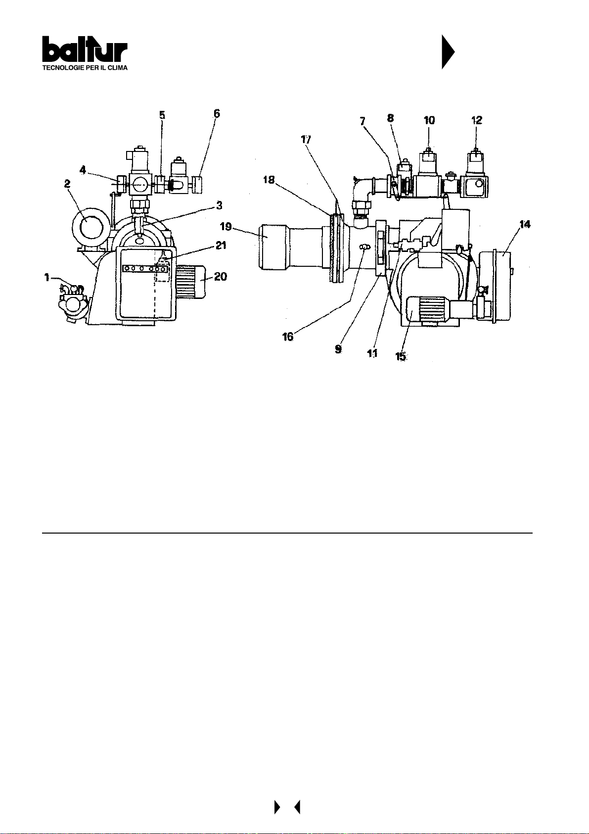
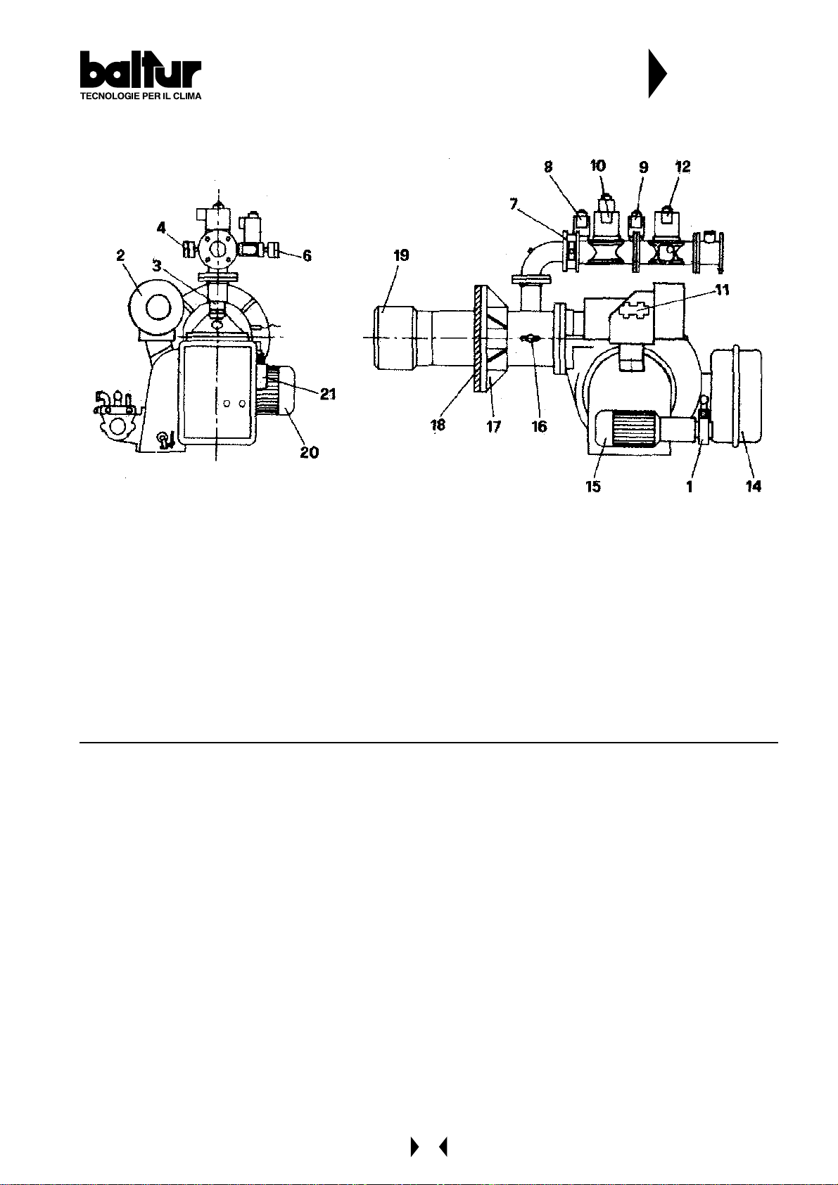
Elenco componenti
Component List
Lista de los componentes
N° 0002570030
Rev.
1 - Pompa
2 - Modulatore
3 - Pressostato aria
4 - Pressostato gas minima
5 - Pressostato gas massima
6 - Pressostato gas massima
7 - V alvola a farfalla
8 - Valvola funzionamento rampa pilot a
9 - Cerniera
10 - Valvola funzionamento
1 - Pump
2 - Modulator
3 - Aire pressure switch
4 - Gas pressure switch min.
5 - Gas pressure switch max.
6 - Gas pressure switch max.
7 - Butterfly
8 - Pilot main valve
9 - Hinge
10 - Main valve
1 1 - Regulation valve return pressure
12 - Safety valve
14 - Electric board
15 - Pump motore
16 - Combustion head air control knob
17 - Burner fixing flange
18 - Gasket
19 - Combustion head
20 - Fan motor
21 - Electromagnet
11 - Valvola regolatrice di pressione
12 - V alvola di sicurezza
14 - Quadro elettrico
15 - Motore pompa
16 - Vite regolazione aria alla testa di combustione
17 - Flangia attacco bruciatore
18 - Guarnizione isolante
19 - Testa di combustione
20 - Motore ventola
21 - Elettromagnete
1 - Bomba
2 - Modulator
3 - Presóstato aire
4 - Presóstato gas mínima
5 - Presóstato gas máxima
6 - Presóstato gas máxima
7 - Válvula de mariposa
6 - Válvula funcionamiento tren piloto
9 - Bisagra
10 - Válvula de funcionamiento
1 1 - Válvula de regulación presión
12 - Válvula de seguridad
14 - Cuadro eléctrico
15 - Motor bomba
16 - Tornillo regulaciónaire en el cabezal de combustión
17 - Brida unión quemador
18 - Empaquetadura aislante
19 - Cabezal de combustión
20 - Motor ventilador
21 - Electroimán
4
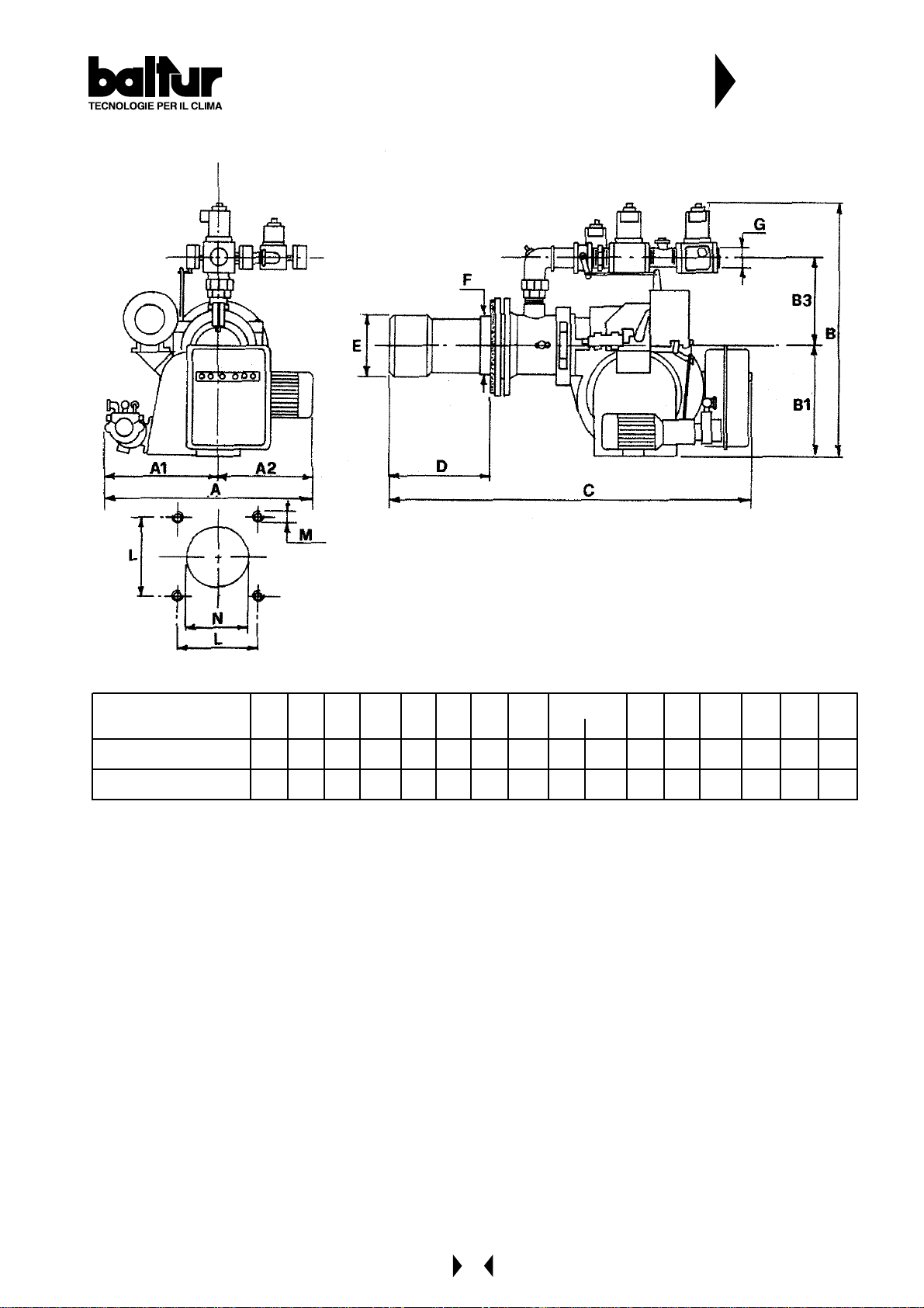
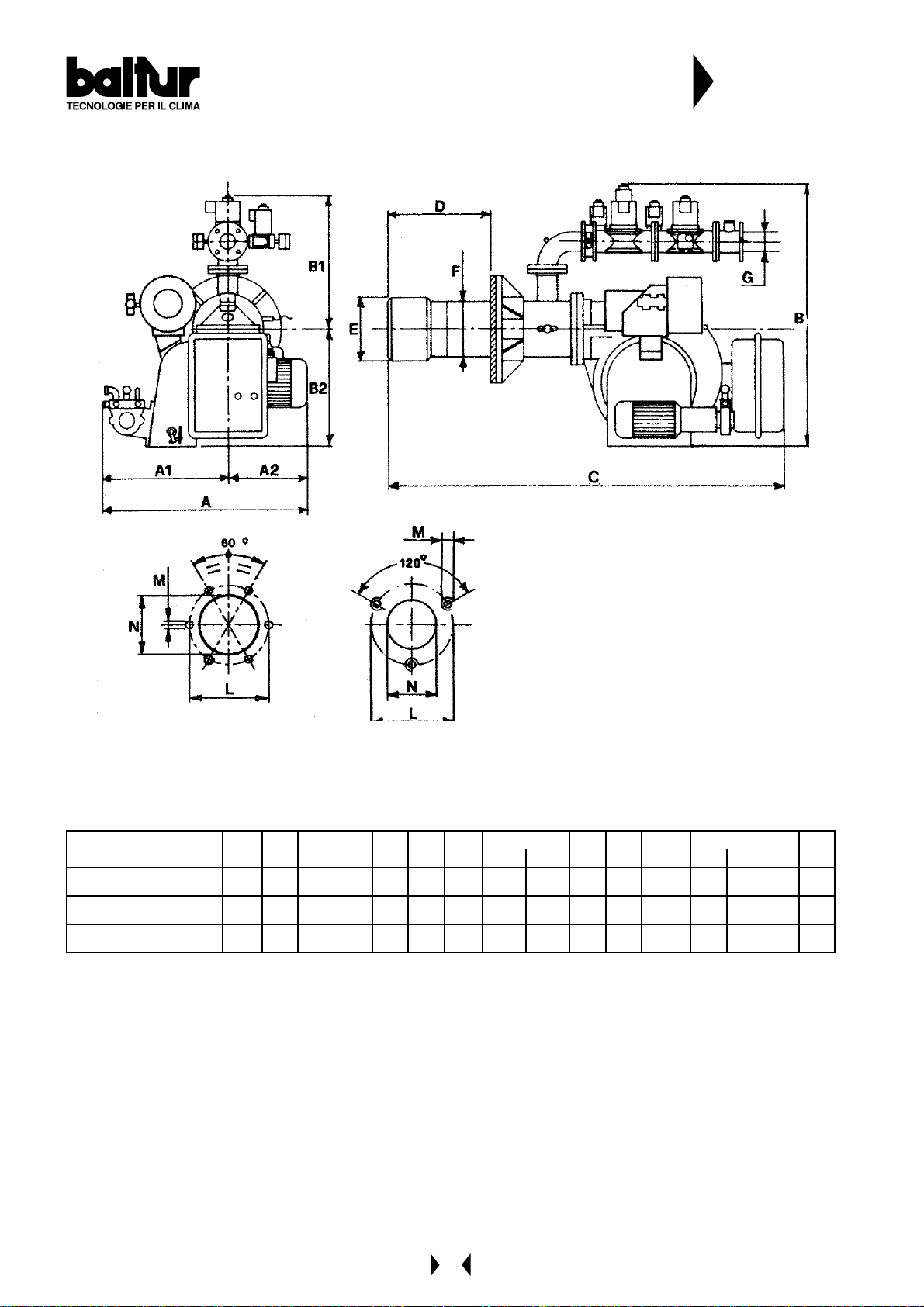
Dimensioni / Dimensions / Dimensiones
N° 0002570030
Rev.
MOD.
COM IST 7 2 DSPG M
COMI S T 122 DS P GM
A A1 A2 B B1 B2 B3 C D E F G L M N
MIN MAX Ø Ø Ø Ø
670 400 270 810 375 43 5 265 1410 185 445 227 220 2" 240 M16 240
830 460 370 1170 455 715 - 1500 195 455 227 220 2"1/2 240 M16 240
5
CARA TTERISTICHE TECNICHE
W
W
TECHNICAL DA T A
CARACTIRÍSTICAS TÉCNICAS
N° 0002570100
Rev.
CARATTERIS T ICHE TECNICHE / T ECHNICAL DAT A
CARACTERÍST ICAS T ÉCNICAS / T ECHNIS CHE DAT EN
POTENZA TERMICA / THERMIC CA PACITY /
POTENCIA TÉRMICA / HEIZLEISTUNG
PORTATA / FLOW RATE / CAUDAL / DURCHSATZ
PRESSIONE MIN.(*) / MIN. PRESSURE (*) /
METANO /
PRESIÓN METANO MÍN. (*) / DRUCK MIN. (*)
NATURAL GAS
TRASFORMATORE METANO / NAT. GAS TRANSFORMER /
TRANSFORMADORES DE ENCENDIDO METANO
POTENZA TERMICA / THERMIC CA PACITY /
POTENCIA TÉRMICA / HEIZLEISTUNG
PORTATA / FLOW RATE / CAUDAL / DURCHSATZ
VISC OSIT A ' COMBUSTIBILE / FU EL VISCO SITY / VISCOSIDAD COMBUSTIBLE
TRASFORMATORE GASOLIO / LI GHT OIL TRANSFORMER
GASÓLEO / HEIZÖL
GASOLIO /LIGHT OIL
TRANSFORMADORES DE ENCENDIDO GASÓLEO / ZÜNDTRAFO
MODELL O / M O DEL /
MODELO / MODELL
COMIST 180 COMIST 250 COMIST 300
DSPGM DSPGM DSPGM
MAk
MI k
MAX m³/h 199 340 390
MIN m³/h 69 113 131
CE
bar 37 150 150
1981 33 80 3878
688 1127 1304
8 kV - 20 mA
MAX kW 1981 3380 3878
MIN kW 688 1127 1304
MAX kg/h 167 285 327
MIN kg/h 58 95 110
1,5° E a/at 20° C
12 kV - 30 mA
14 kV - 30 mA 14 kV - 30 mA
TENSIONE / VOLTA GE / TENSIÓN / SPANNUNG
MOTORE VENTOLA / FAN MOTOR /
MOTORES VENTILA DOR / LÜFTERMOTOR
MOTORE POMPA / PUMP MOTOR / MOTORES BOMBA / PUMPM OTOR
Vol
kW/r.p.m.
kW/r.p.m.
230/ 400 - 50 Hz
3 - 2870 7, 5 - 2870 7,5 - 2870
0,75 - 28 00 1, 5 - 2800 1,5 - 2800
MAT ERI A L E A CO RREDO / S T ANDARD ACCESSO RIES / MATERI AL EN DOTACIÓN / STANDAR DZUBEHÖR
FLANGIA ATTACCO BRUCIAT. / BURNER FIXING FLANGE /
BRIDA UNIÓN / BEFESTIGUNGSFLANSCH
COLLARE ELASTICO / ELASTIC COLLAR / COLLARÍN ELÁSTICO / FEDER
GUARNIZIONE ISOLANTE / INSULATING GASKET /
EMPAQUETADURA / ISOLIERDICHTUNG
FILTRO / FILTE R
TUBI FLESSIBILI / FLEXIBLE PIPE / TUBOS FLEXIBLES / SCHLÄUCHE
PRIGIONIERI / STUD BOLTS / ESPÁRRAGOS / STIFTSCHRAUBEN
DADI / EXAGONAL NUTS / TUERCAS / SECHSKANTMUTTERN
RONDELLE PIA NE / FLA T WA SHERS / A RANDELA S / FLACHSCHEIBEN
111
- - 1 1
222
1"¼ 1"¼ 1"1/4
N°2
1"¼x1"¼
N°2
1"¼x1"¼
N°2
1"¼x1"¼
N°6 M20N°3 M20N°3 M20
N°6 M20N°3 M20N°3 M20
N°6 ø20N°3 ø20N°3 ø20
6
CARA TTERISTICHE TECNICHE
TECHNICAL DA T A
CARACTIRÍSTICAS TÉCNICAS
N° 0002570100
Rev.
1 - Pompa
2 - Modulatore
3 - Pressostato aria
4 - Pressostato gas minima
5 - Pressostato gas massima
6 - Pressostato gas massima
7 - Valvola a farfalla
8 - Valvola funzionamento rampa pilot a
9 - Valvola sicurezza rampa pilot a
10 - Valvola funzionamento
1 - Pump
2 - Modulator
3 - Aire pressure switch
4 - Gas pressure switch min.
5 - Gas pressure switch max.
6 - Gas pressure switch max.
7 - Butterfly
8 - Pilot main valve
9 - Pilot safety valve
10 - Main valve
1 1 - Regulation valve return pressure
12 - Safety valve
14 - Electric board
15 - Pump motore
16 - Combustion head air control knob
17 - Burner fixing flange
18 - Gasket
19 - Combustion head
20 - Fan motor
21 - Electromagnet
1 1 - V alvola regolatrice di pressione
12 - Valvola di sicurezza
14 - Quadro elettrico
15 - Motore pompa
16 - Vite regolazione aria alla testa di combustione
17 - Flangia attacco bruciatore
18 - Guarnizione isolante
19 - Testa di combustione
20 - Motore ventola
21 - Elettromagnete
1 - Bomba
2 - Modulator
3 - Presóstato aire
4 - Presóstato gas mínima
5 - Presóstato gas máxima
6 - Presóstato gas máxima
7 - Válvula de mariposa
6 - Válvula funcionamiento tren piloto
9 - Válvula de seguridad tren piloto
10 - Válvula de funcionamiento
1 1 - Válvula de regulación presión
12 - Válvula de seguridad
14 - Cuadro eléctrico
15 - Motor bomba
16 - T ornillo regulaciónaire en el cabezal de combustión
17 - Brida unión quemador
18 - Empaquetadura aislante
19 - Cabezal de combustión
20 - Motor ventilador
21 - Electroimán
7
Dimensioni / Dimensions / Dimensiones
M
M
M
N° 0002570100
Rev.
Mod.
COMIST 1 80 DSP G
COMIST 2 50 DSP G
COMIST 3 00 DSP G
AA1A2BB1B2CDEFGLMN
min max min max
875 460 415 1225 510 715 1725 330 520 260 245 2”1/ 2G 400 400 M 20 300
1075 540 535 1300 580 720 1750 320 500 320 273 3”G 490 490 M 20 340
1075 540 535 1300 580 720 1750 320 500 320 273 3”G 490 490 M 20 350
8
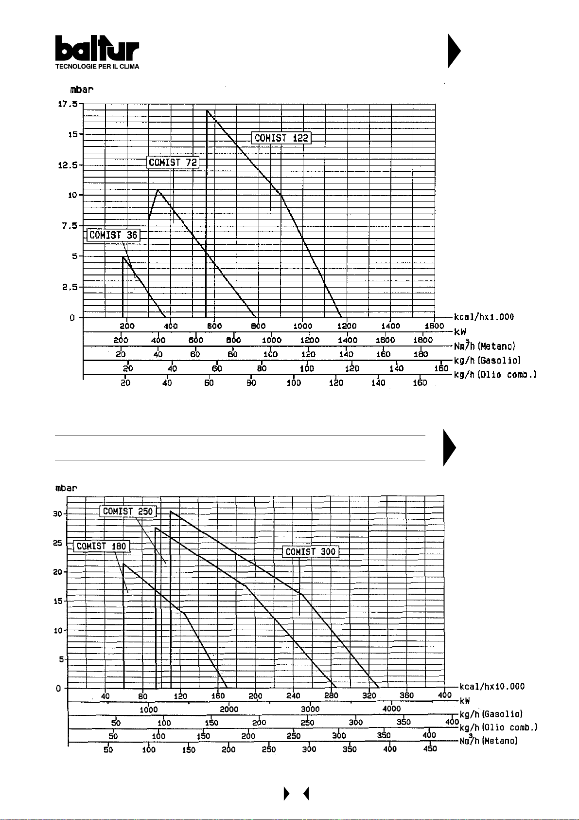
COMIST 36 - 72 - 122
N° 8187/1
Rev.
COMIST 180 - 250 - 300
N° 8111/2
Rev.
9
DRAWING SHOWING THE GAS TRAIN ASSEMBL Y
COMIST 72 MG - DSPGM
N° 8805
Rev.
DRAWING SHOWING THE GAS TRAIN ASSEMBL Y
COMIST 122 - 180 - 250 - 300 MG - DSPGM - DSPNM
N° 8797
Rev.
10
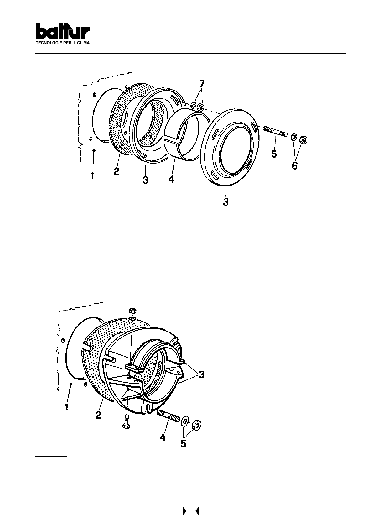
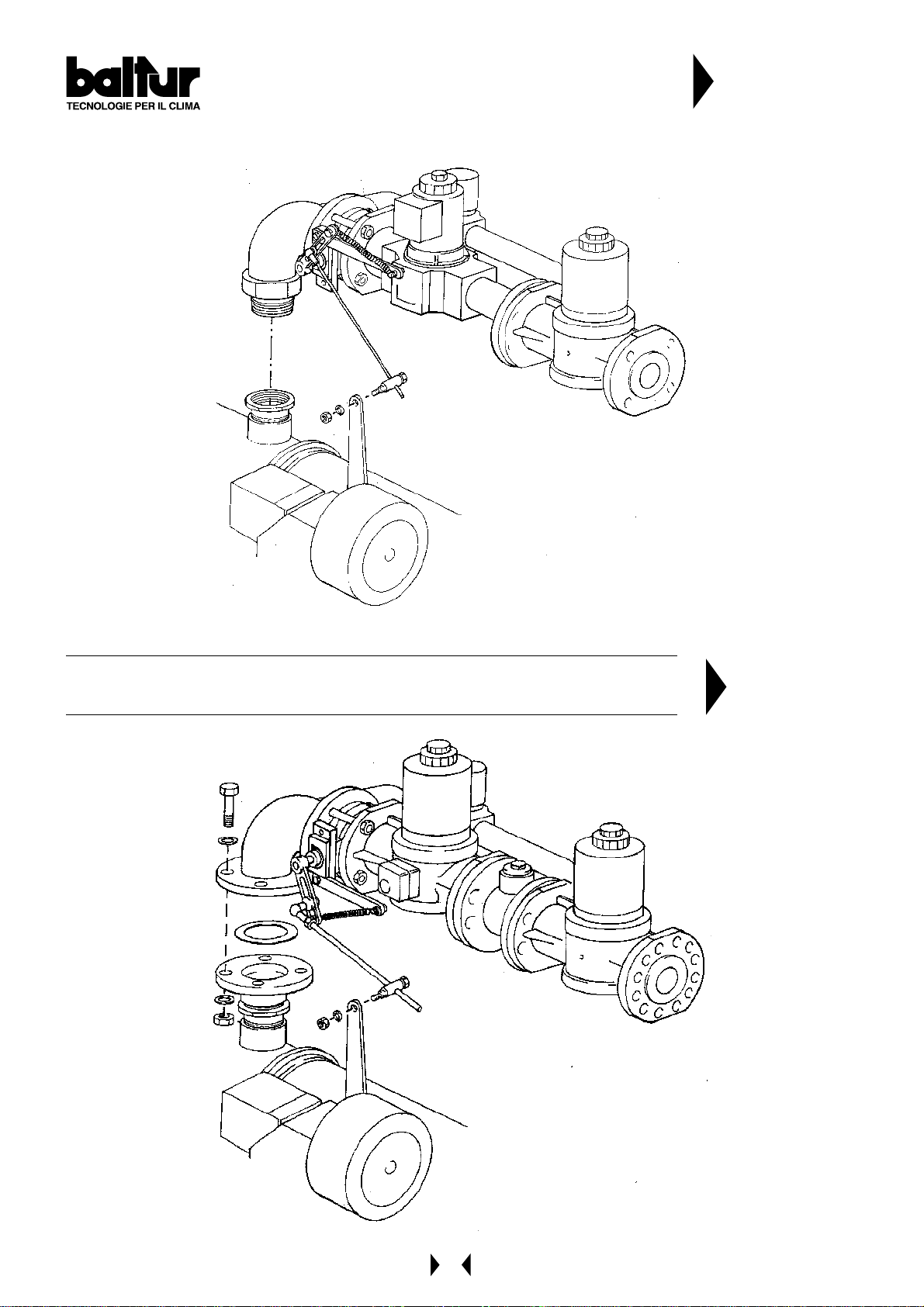
APPLICATION OF THE BURNER TO BOILER
for model COMIST 72 - 122 DSPGM (steel fixing flange)
1 - Boiler plate
2 - Insulating gasket
3 - Burner fixing flange
4 - Elastic collar
for model COMIST 250 - 300 DSPGM
5 - Stud bolt
6 - Locking nut with washer
7 - Nut and washer for fastening the first flange
1 - Boiler plate
2 - Insulating gasket
3 - Burner fixing flange
4 - Stud bolt
5 - Locking nut with washer
REMARKS
When tightening the flange, it is important to do it evenly so that the inner faces are parallel between them.
Since the locking system is highly efficient, do not tighten the nuts too much.
During this operation (tightening of the flange locking nuts) keep the body of the burner lifted so that the
combustion head is kept in a horizontal position.
11
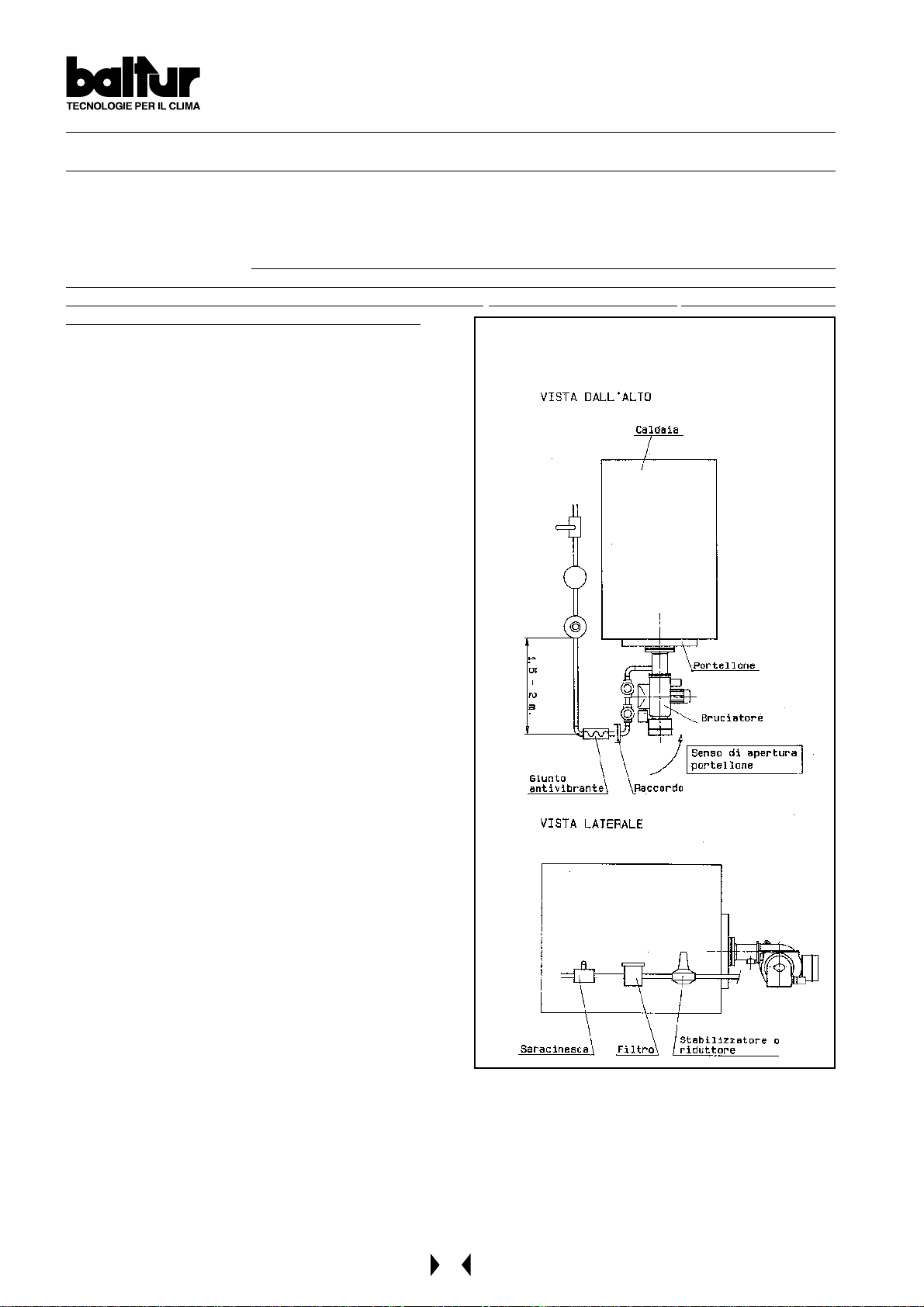
GAS FEED SYSTEM AT LOW PRESSURE ( max. 400 mm.C.A )
When the burner has been correctly fastened to the boiler, proceed with connecting it to the gas pipeline
(see BT 8780 and BT 1387). The dimension of the gas adduction pipeline should be in proportion to its length and
to gas delivery and the load loss should not exceed 5 mm W. C. (see diagram). It must also be perfectly hermetic
and adequately tested before the burner’s general inspection. It is indispensable to install a proper fitting on the
pipeline, in proximity to the burner, to allow for easy disassembling of the burner and/or opening of the boiler door .
In addition, the following should be installed: a cut -off cock, a gas filter , a st abilizer or a pressure regulator (when
the feed pressure is superior to 400 mm W. C. = 0,04 Kg/cm2), and an antivibration joint. These parts should be
installed as described in our drawing (see BT 8780).
We consider it useful to give the following practical tips for
installing the essential accessories on the gas pipeline near
to the burner:
1) To avoid big drops in pressure on ignition, the length of
the pipeline between the point where the stabilizer or
reducer is fitted and the burner should be from 1,5 to 2
m. This pipe must have a diameter equal or superior to
that of the burner attachment fitting.
2) The fitting must be applied on horizontal pipes.
This is to avoid any impurities falling into the pipes or
entering the stabilizer during cleaning.
3) T o get the best performance out of the pressure st abilizer,
it is advisable to fit it onto horizontal pipes, after the filter .
In this way, the vertical movement of the entire mobile
part (shutter) of the stabilizer is rapid. (If the movement
of the mobile part were horizontal - with the stabilizer
fitted into vertical pipes - friction to the guide bush/es of
the pin to which the entire mobile part is fitted would
delay movement).
GENERAL DIAGRAM FOR INSTALLATION OF
GATE-FILTER-STABILIZER-ANTIVIBRA TION JOINT
OPENABLE PITTING
N° BT 8780
4) We advise installing a bend directly onto the burner gas
ramp before applying the removable fitting. This layout
makes it possible to open the boiler door, if there is one,
after the pipe fitting itself has been opened. The above
information is clearly illustrated in drawing BT 8780.
12
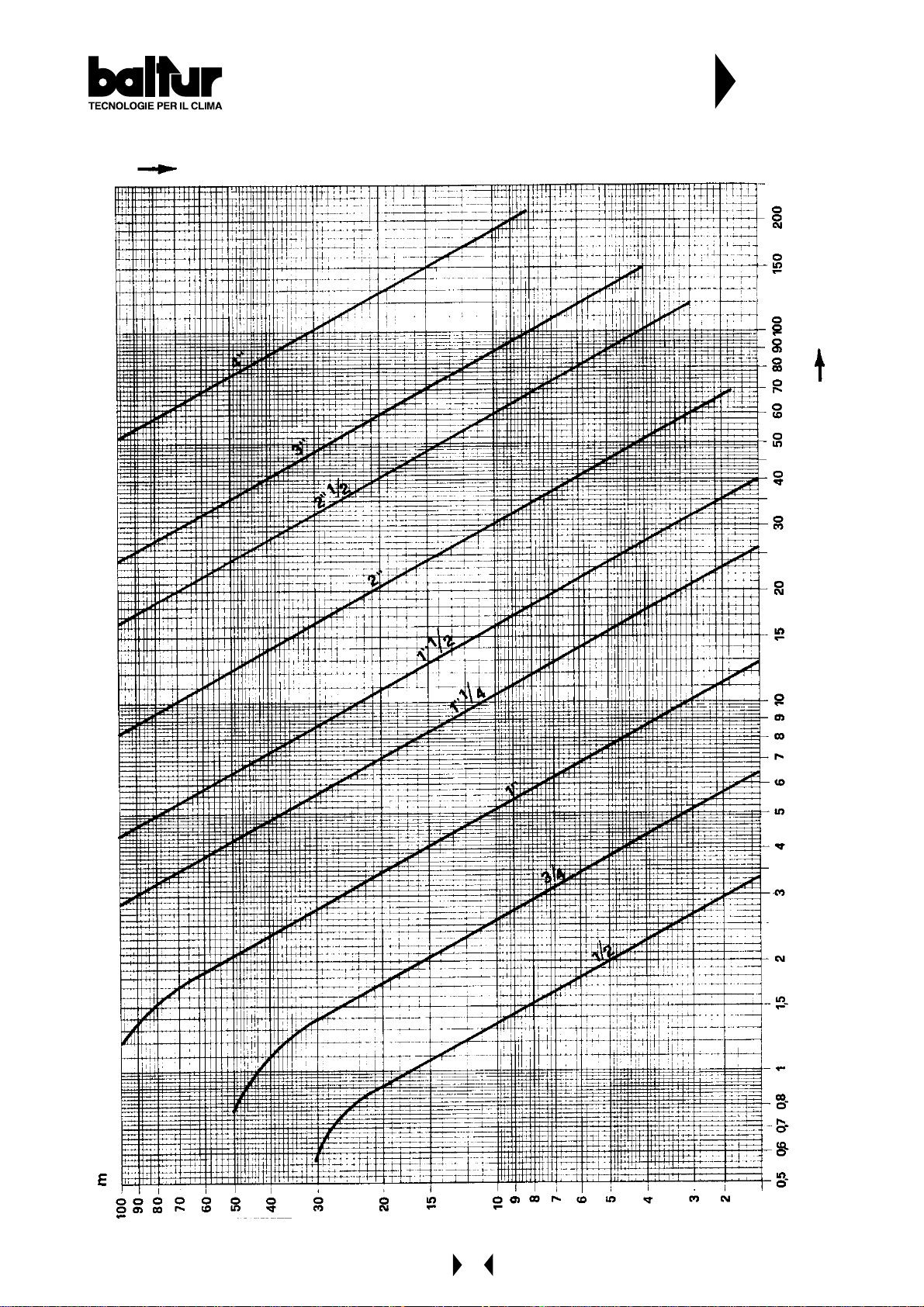
FLOW (m3/h) METHANE GAS (d=0,85) IN
COMMERCIAL GAS PIPES (UNI 3824-68)
LOAD LOSS MAX. 5 mm W . C.
VIRTUAL LENGTH IN METERS
N° BT 1387
/h
3
FLOW m
13
GAS FEED SYSTEM AT AVERAGE PRESSURE a few bars (see BT 8058-BT 8530/1-8531/1)
When high delivery is required, the Gas
Distributing Company requests the installation of
a unit comprising a pressure reducer and a meter,
and then connects it to the gas pipe network at
average pressure (a few bars).
This unit can be supplied by the Gas Distributing
Company or by the user , but should be according
to the Gas Company’s precise instructions.
The unit’s pressure reducer should be large
enough to supply the maximum gas delivery
required by the burner at the rate of pressure
normally estimated for it.
From experience, we would recommend utilising
a large-scale reducer in order to attenuate the
notable increase in pressure which occurs when
the burner comes to a standstill, with a high
delivery . (Regulations require that the gas valves
close in less than one second).
As an indication, we would advise using a reducer
capable of producing at delivery (m3/h) about
double that of the maximum amount estimated
for the burner.
If several burners are to be used, each one should
have its own pressure reducer; this will enable
the gas feed pressure to the burner to be
maintained at a constant level even if only one
burner is operating at the time.
Consequently , it is possible to accurately regulate
the delivery and therefore the combustion, and
thus improve yield.
The dimension of the gas pipeline should be in
function with the quantity of gas it has to deliver.
We advise maintaining the load loss at a low level
(not more than 10% of the gas pressure value at
the burner); it should be kept in mind that the
load loss is added to the pressure existing when
the burner stops and therefore a subsequent start
up will occur at a pressure that rises in
accordance with an increase in the pipe’s load
loss. Should the gas pressure reach
unacceptable values when the burner stops
(rapid closure of the gas valves), it is necessary
to install between the reducer and the first valve
of the burner an automatic overflow valve and
relative conveying pipe, of suitable section, in the
open air.
The end of conveying pipe in the open air should terminate in a suitable place, be protected from rain and have a
flame trap. The overflow valve should be regulated in such a way as to completely unload excessive pressure.
See diagram BT 8058 for gas pipeline dimensions.
Near to the burner should also be fitted a cut-off ball cock, a gas filter , an anti-vibration joint and a flanged fitting
(see BT 8530/1 and BT 8531/1).
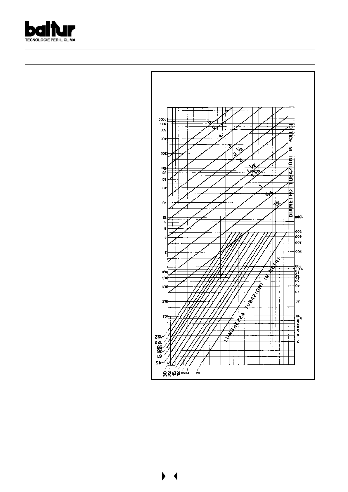
DIAGRAM FOR CALCULATING THE DIAMETER OF THE
PIPES IN RELATION TO THEIR LENGTH AND GAS FLOW
/h OF METHANE p.a. 0,60
c
FLOW IN m
LENGTH OF PIPES IN METERS
DIAMETER OF PIPES IN INCHES
O
2
PRESSURE DROP IN mm OF H
N° BT 8058
14
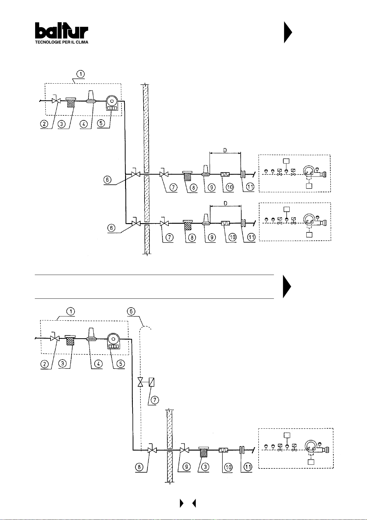
DIAGRAM OF CONNECTING MORE THAN ONE
BURNER TO THE GAS PIPE NETWORK
A T A VERAGE PRESSURE
1 - Measuring and reducing unit
2 - Interception
3 - Filter
4 - Reducer
5 - Meter
6 - Emergency interception (installed outside)
7 - Ball cock
8 - Filter
9 - Final reducer or stabilizer
10- Anti-vibration joint
11- A couple of flane
D = Distance between pressure stabilizer and valve about 1,5 ÷ 2 m
N° BT 8530/1
DIAGRAM OF CONNECTING A BURNER TO THE GAS PIPE NETWORK AT
A VERAGE PRESSURE
1 - Measuring and reducing unit
2 - Interception
3 - Filter
4 - Reducer
5 - Meter
6 - Wire gauze flame trap
7 - Eventual automatic overflow valve (it should obviously
unload outside in a suitable place)
8 - Emergency interception installed outside
9 - Ball cock
10- Anti-vibration joint
11- A couple of flange
N° BT 8531/1
15
ELECTRICAL CONNECTIONS
It is advisable to make all connections with flexible electric wire.
The electric lines should be at an adequate distance from hot parts.
Make sure that the electric line to which the unit will be connected has frequency and voltage ratings suitable for
the burner.
Check that the main line, the relevant switch with fuses (essential) and the current limiter (if required) are capable
of withstanding the maximum current absorber by the burner .
For details, refer to the specific electric diagram for each single burner .
FUEL FEED SYSTEM
The burner pump should receive fuel from a feed circuit which has an ancillary pump and, in some cases, a
pressure regulator capable of modifying the pressure value 0,2 to 1 bar (see drawing BT 0002901120).
In this case, the value of the fuel feed pressure at the burner pump (0,2 ÷ 1 bar) should not vary when the burner
is at a standstill or when it is operating at the maximum fuel delivery required by the boiler.
Normally it is possible to realize a circuit without a pressure regulator as shown in drawing n° BT 8666/3.
The feed circuit must be realized according to drawing 0002901 120 or to drawing BT 8666/3.
The dimension of the pipelines should be in function with their length and with the output of the pump utilized.
Our instructions cover the basic requirements needed to ensure efficient operations.
All rules and regulations existing in the country of installation should be strictly complied with and the local fire
brigade should be consulted.
FURTHER INSTRUCTIONS TO START A MIXED BURNER
It is advisable to first carry out the starting with the liquid fuel because in this case the delivery is conditioned by the
available nozzle whereas the delivery of methane be varied as you like by working on its delivery regulator .
16
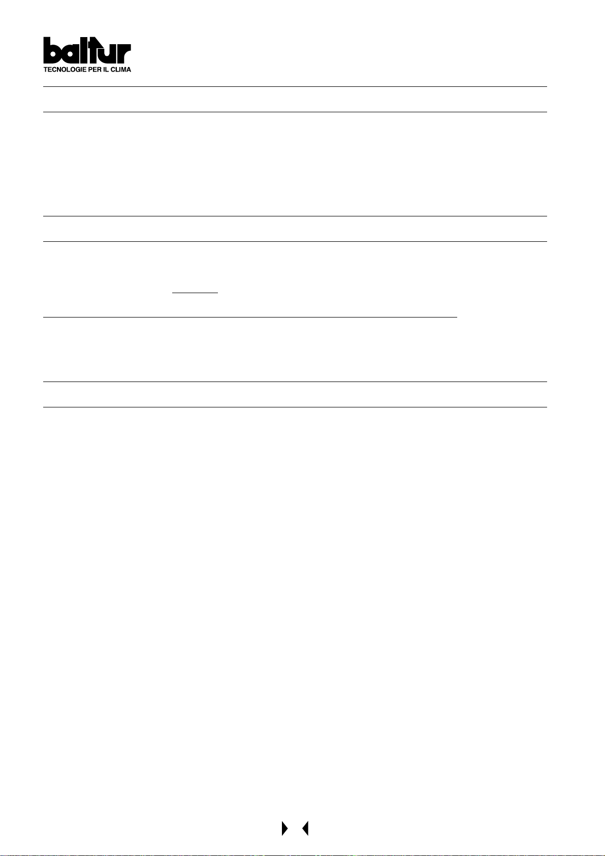
FUEL FEEDING HYDRAULIC DIAGRAM FOR ONE
OR MORE LIGHT OIL BURNERS
WITH MAXIMUM NOMINAL VISCOSITY (5 °E at 50 °C)
1 Main cictern
2 Filter
3 Circulation pump
4 Water and system drain
6 Fuel recovery and degasifier
7 One-way valve
8 By-pass (usually closed)
9 Feeding circuit presure regulator adjustment range between 0.2 and 1 bar
10 Pressure gauge (0 - 4 bar)
The combustible recovery and degasifier
tanks (diameter ~ 150, height ~ 400)
should be installed as near as possible
to the burner and should be about 0,5 m.
higher with respect to the burner's pump.
N° 0002901 120
rev.:19/02/2002
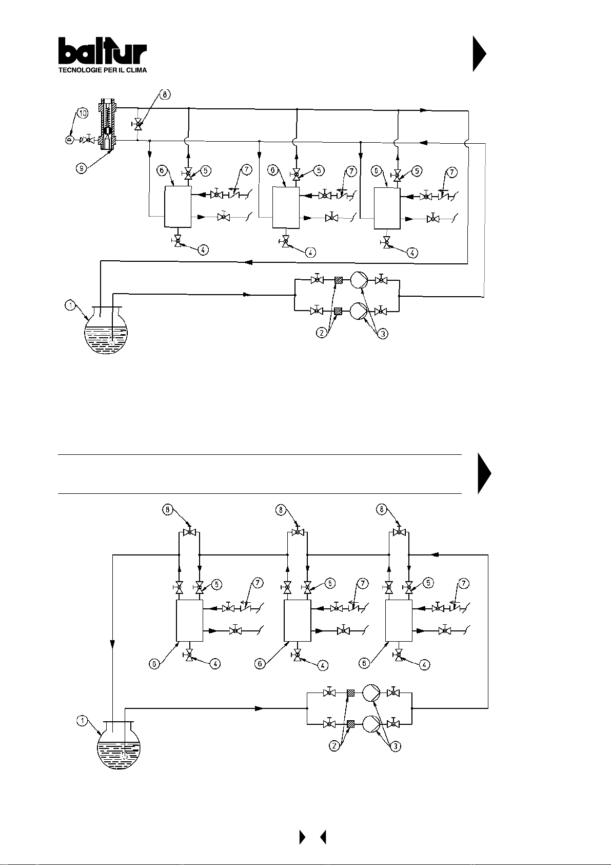
DIAGRAM OF PIPES OF FEED SYSTEM FOR LIGHT OIL BURNERS
WITH MAXIMUM NOMINAL VISCOSITY (5 °E at 50 °C)
1 Main cictern
2 Filter
3 Circulation pumps
4 Water and system drain
5 Air-gas drain usually closed
6 Fuel recovery and degasifier
7 One-way valve
8 By-pass (usually closed)
The combustible recovery and degasifier tanks (diameter
~ 150, height ~ 400) should be installed as near as
possible to the burner and should be about 0,5 m. higher
with respect to the burner's pump.
N° BT 8666/3
17
DESCRIPTION OF TWO ST AGE PROGRESSIVE OPERATIONS WITH LIGHT OIL
COMIST...DSPGM (See BT 8714/2)
This is referred to as a 2-stage progressive operation because the passage from the 1st flame to the 2nd flame
(from the minimum rate to the maximum pre-established rate) takes place gradually both as delivery of combustion
air and of fuel. The burner’s control box (cyclic relay) is connected by operating panel switch ( I ).
Control box specifications
Control box
& relative
Programmer
LFL 1.333
Cyclic relay
The cyclic relay control box carries out the ignition programme by starting up the fan motor and thus the pump in
order to effect the pre-ventilation and light oil pre-circulation phases.
It is necessary that the air pressure supplied by the fan is sufficient to cause the intervention of the relative
pressure switch, if not, the control box will go to “shut down”.
Oil from the pump reaches the atomizer unit and circulates within it because the passages leading to the outward
and return nozzles are closed. This closure is carried out by “closing pins” applied to the ends of the rods.
These “pins” are pressed against their seats by strong springs which are situated at the opposite ends of the rods.
The oil circulates, comes out of the atomizer unit return and arrives at the return pressure regulator.
It passes through this and reaches the pump return and from there it is discharged back into the return.
Oil circulation, as described above, should be carried out at a pressure value slightly higher (by some bar) than the
minimum pressure at which the return pressure regulator has been set (10 ÷ 12 bar).
Duration of the pre-ventilation and oil pre-circulation phase is not as foreseen by the control box, because it is
effected when the air shutter is in an open position.
The pre-ventilation and pre-circulation time is calculated by summing together the times of the following manoeuvres:
- the delivery regulation servomotor’s opening stroke (fuel/air) +
- preventilation time foreseen by the control box +
- the closing stroke of the delivery regulation servomotor (fuel/air) until ignition air position.
Subsequently , the control box continues carrying out the ignition programme by connecting the ignition transformer
which feeds the electrodes with high voltage. The voltage between the electrodes primes the electric spark for
ignition of the fuel/air mixture. After the insertion spark appears, the control box carries voltage to the magnet
which, by means of appropriate levers, moves backwards the two rods which intercept the flow (outward and
return) of light oil to the nozzle. This moving backwards of the rods also determines a closing of the passage (bypass) inside the atomizer unit. Consequently , the pump pressure is taken to the normal value of about 20 ÷ 22 bar .
Deviation of the two rods the closing seat, now permits the fuel to enter the nozzle at the pressure at which the
pump has been regulated at (20 ÷ 22 bar), and comes out of the nozzle adequately atomized.
The return pressure, which determines delivery to the furnace, is regulated by the return pressure regulator.
The value of the ignition flow rate (minimum delivery) should be about 10 ÷ 12 bar.
The atomized light oil which comes out of the nozzle is mixed with air supplied by the fan and is then ignited by the
spark of the electrodes. Flame presence is detected by the photocell UV.
The programme proceeds and surpasses the “shut down” position, disconnects the ignition transformer and by
this point on the burner is operating at minimum output.
If the boiler thermostat (or pressure switch) of the 2nd stage allows it (regulated at a temperature or pressure value
superior to that existing in the boiler), the servomotor which regulates the delivery starts turning and determines a
gradual increase in the fuel delivery and in the relative combustion air until it reaches the maximum delivery value
at which the burner has been regulated. The increase in fuel delivery is determined by a disk with a varied profile
which, by rotating, can determine a greater compression of the return pressure regulator spring and thus an
increase in the pressure itself. When the return pressure increases, there is also a corresponding increase in fuel
delivery . There should also be an adequate increase in combustion air to meet the increase in fuel delivery.
Adjustment can be carried out at first regulation by operating the screws which vary the profile of the commend
disk of the combustion air regulator.
Safety
time in
seconds
3
Pre-Ventilation &
Oil Pre-circulation
Time
in seconds
31,5
Pre-ignition
Time
in seconds
6
Post-ignition
Time
in seconds
3
Time between
1st flame & Start
of Modulation
in seconds
12
18
Fuel and combustion air delivery both increase at the same time until they reach maximum value (light oil pressure
at the return pressure regulator is equal to about 18 ÷ 20 bar if the pressure at the pump is at the value of 20 ÷ 22
bar). The burner remains in the maximum delivery position until the temperature or pressure reaches the limit set
for the intervention of the boiler thermostat (or pressure switch) of the 2nd stage and makes the servomotor
regulating fuel/air delivery rotate in the opposite sense of direction, a causing gradual reduction in fuel delivery and
a relative reduction in combustion air until they reach minimum value.
Should the maximum temperature (pressure, if steam boiler), be reached even with fuel and combustion air
delivery at a minimum, the thermostat (pressure switch, if steam boiler) will intervene when the value at which it
has been set is reached, and bring the burner to a standstill. When the temperature (pressure, if steam boiler)
drops below the intervention limit of the “shut down” device, the burner will start up again as previously described.
During normal operations, the boiler thermostat / pressure switch of the 2nd stage fitted to the boiler detects the
variations requested and automatically proceeds with adapting the fuel and combustion air delivery by inserting
the servomotor which regulates delivery (fuel/air). This will rotate in such a way as to obtain an increase or a
decrease. In this way , the delivery regulating system (fuel/air) reaches a position of equilibrium which corresponds
to a fuel delivery and a relative combustion air delivery equal to the quantity of heat required by the boiler.
As in indication, it should be kept in mind that the field of variation in output obtainable with good combustion is
from 1 to 1/3 of the maximum output given on the rating plate.
Note: The air pressure switch must be set when the burner is started up and must be in function with the pressure
value verified during operations with the ignition flame; otherwise the control box will go to “shut down”.
DESCRIPTION OF MODULATING OPERATIONS WITH LIGHT OIL (COMIST...MM) (See BT 8714/2)
The burner’s control box (cyclic relay) is connected by operating panel switch ( I ).
Control box specifications
Control box
& relative
Programmer
LFL 1.333
Safety Time
in seconds
3
Pre-Ventilation &
Oil Pre-circulation
Time
in seconds
31,5
Pre-ignition
Time
in seconds
6
Post-ignition
Time
in seconds
3
Time between
1st flame & Start
of Modulation
in seconds
12
Cyclic relay
The cyclic relay control box carries out the ignition programme by starting up the fan motor and thus the pump in
order to effect the pre-ventilation and light oil pre-circulation phases.
It is necessary that the air pressure supplied by the fan is sufficient to cause the intervention of the relative
pressure switch, if not, the control box will go to “shut down”.
Oil from the pump reaches the atomizer unit and circulates within it because the passages leading to the outward
and return nozzles are closed.
This closure is carried out by “closing pins” applied to the ends of the rods.
These “pins” are pressed against their seats by strong springs which are situated at the opposite ends of the rods.
The oil circulates, comes out of the atomizer unit return and arrives at the return pressure regulator.
It passes through this and reaches the pump return and from there it is discharged back into the return.
Oil circulation, as described above, should be carried out at a pressure value slightly higher (by some bar) than the
minimum pressure at which the return pressure regulator has been set (10 ÷ 12 bar).
Duration of the pre-ventilation and oil pre-circulation phase is not as foreseen by the control box, because it is
effected when the air shutter is in an open position.
The pre-ventilation and pre-circulation time is calculated by summing together the times of the following manoeuvres:
- the delivery regulation servomotor’s opening stroke (fuel/air) +
- pre-ventilation time foreseen by the control box +
- the closing stroke of the delivery regulation servomotor (fuel/air) until ignition air
position .
Subsequently , the control box continues carrying out the ignition programme by connecting the ignition transformer
which feeds the electrodes with high voltage.
The voltage between the electrodes primes the electric spark for ignition of the fuel/air mixture.
19

After the insertion spark appears, the control box carries voltage to the magnet which, by means of appropriate
levers, moves backwards the two rods which intercept the flow (outward and return) of light oil to the nozzle.
This moving backwards of the rods also determines a closing of the passage (by-pass) inside the atomizer unit.
Consequently , the pump pressure is t aken to the normal value of about 20 ÷ 22 bar.
Deviation of the two rods from the closing seat, now permits the fuel to enter the nozzle at the pressure at which
the pump has been regulated at (20 ÷ 22 bar), and comes out of the nozzle adequately atomized.
The return pressure, which determines delivery to the furnace, is regulated by the return pressure regulator.
The value of the ignition flow rate (minimum delivery) should be about 10 ÷ 12 bar.
The atomized light oil which comes out of the nozzle is mixed with air supplied by the fan and is then ignited by the
spark of the electrodes. Flame presence is detected by the photocell UV.
The programme proceeds and surpasses the “shut down” position, disconnects the ignition transformer , and then
connects the modulation circuit. The modulation motor commands an increase in the delivery of fuel and combustion
air at the same time. The increase in fuel delivery is determined by a disk with a varied profile which, by rotating,
can determine a greater compression of the return pressure regulator spring and thus an increase in the pressure
itself. When the return pressure increases, there is also a corresponding increase in fuel delivery.
There should also be an adequate increase in combustion air to meet the increase in fuel delivery .
Adjustment can be carried out at first regulation by operating the screws which vary the profile of the commend
disk of the combustion air regulator. Fuel and combustion air delivery both increase at the same time until they
reach maximum value (light oil pressure at the return pressure regulator is equal to about 18 ÷ 20 bar if the
pressure at the pump is at the value of 20 ÷ 22 bar). Fuel and combustion air delivery remain at maximum value
until the boiler temperature (pressure, if steam boiler), approaches the value at which it has been set and causes
the servomotor regulating fuel/air delivery to reverse its previous sense of movement. The return movement of the
modulation causes a reduction in light oil delivery and a relative reduction in combustion air.
The modulation system reaches a position of equilibrium which corresponds to a fuel delivery and a relative
combustion air delivery equal to the quantity of heat required by the boiler. With the boiler operating, the probe in
the boiler is aware of load variation in the boiler and automatically commands the modulation motor to make an
adjustment in the light oil delivery and in the relative combustion air.
Should the maximum temperature (pressure, if steam boiler), be reached even with fuel and combustion air
delivery at a minimum, the thermostat (pressure switch, if steam boiler) will intervene when the value at which it
has been set is reached, and bring the burner to a standstill. When the temperature (pressure, if steam boiler)
drops below the intervention limit of the “shut down” device, the burner will start up again as previously described.
The air pressure switch must be regulated at the burner ignition, in relation to the pressure value obtained whit
ignition flame; on the contrary the control box stops in lock position.
Note: As an indication, it should be kept in mind that the field of variation in output obtainable with a good quality
fuel is from 1 to 1/3 of the maximum output given on the rating plate.
20
CONNECTION AT THE
FUEL FEEDING
DIAGRAM FOR ONE
OR MORE BURNERS
(SEE 0002901120)
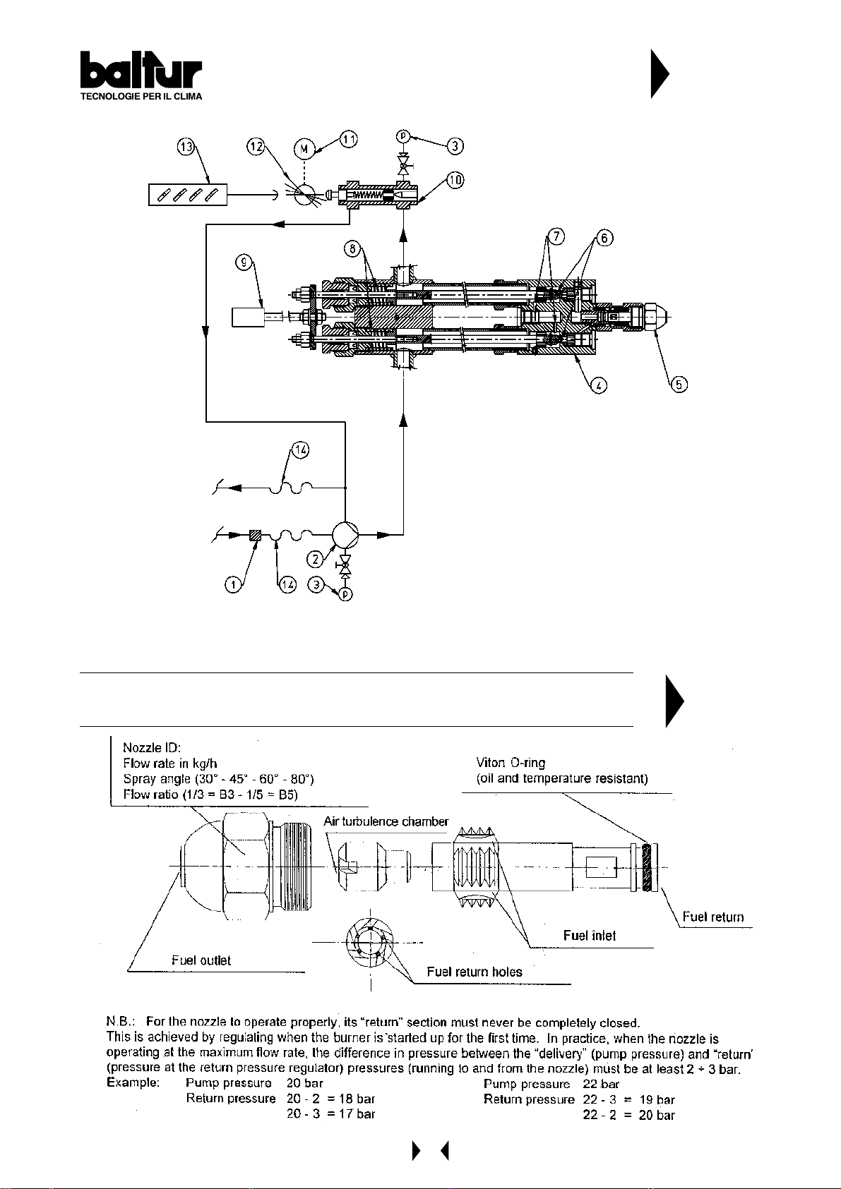
DIAGRAM OF LIGHT OIL MODULATING
BURNERS ( MAGNET - NOZZLE WITHOUT PIN)
1 FILTER
2 BURNER PUMP
3 PRESSURE GAUGE 0 - 40 BAR
4 ATOMIZER UNIT
5 RETURN NOZZLE WITHOUT PIN
6 ROD WITH CLOSING PINS
7 BY-PASS HOLES
8 CLOUSING SPRING
9 OPENING ELECTROMAGNET
10 RETURN PRESSURE REGULATOR
11 MODULATION SERVOMOTOR
12 CONTROL DISK FOR VARIATION OF FUEL / AIR DELIERY
13 AIR REGULATION SHUTTERS
14 FLEXIBLE PIPE
N° BT 8714/2
REV .: 19/02/2002
MIN = 10-12 BAR
MAX = 18-20 BAR
DIAGRAM OF A DISMANTLED ( C.B. ) CHARLES BERGONZO NOZZLE
(WITHOUT PIN)
N° BT 9353/1
21
 Loading...