

baltur BT 75 DSPG, BT 100 DSPG, BT 120 DSPG, BT 300 DSPG, BT 180 DSPG Maintenance, Use And Installation Manual
...
EN
Maintenance,
use and
installation
manual
SP
Manual de
mantenimiento,
uso e
instalación
РУС
Инструкция по
монтажу,
эксплуатации,
техническому
обслуживанию
BT 75 DSPG
BT 100 DSPG
BT 120 DSPG
BT 180 DSPG
BT 250 DSPG
BT 300 DSPG
98319_200910


- Before using the burner for the rst time please carefully read the chapter “WARNINGS NOTES FOR THE USER : HOW
TO USE THE BURNER SAFELY” in this instruction manual, which is an integral and essential part of the product.
- The works on the burner and on the esystem have to be carried out only by competent people.
- Read carefully the instructions before starting the burner and service it.
- The system electric feeding must be disconnected before starting working on it.
- If the works are not carried out correctly it is possible to cause dangerous accidents.
- Antes de empezar a usar el quemador lea detenidamente el folleto “ADVERTENCIAS DIRIGIDAS AL USUARIO PARA USAR CON SEGURIDAD EL QUEMADOR” que va con el manual de instrucciones y que constituye una parte integrante y esencial del producto.
- Lea atentamente las instrucciones antes de poner en funcionamento los quemadores y efectuar las tareas de mantenimiento.
- Los trabajos que se efectúen al quemador y a la instalación deben ser efectuados sólamente por personal cualicado.
- La alimentación eléctrica de la instalación se debe desconectar antes de iniciar los trabajos.
- Si los trabajos no son efectuados correctamente se corre el riesgo de que se produzcan accidentes peligrosos.
E
N
G
L
I
S
H
E
S
P
A
Ñ
- Передначаломэксплуатациигорелки внимательноознакомьтесьс содержанием данной брошюры
“ПРЕДУПРЕЖДЕНИЯ ПОЛЬЗОВАТЕЛЮПО БЕЗОПАСНОЙ ЭКСПЛУАТАЦИИ ГОРЕЛКИ”, которая
входитв комплект инструкции,и, котораяявляетсянеотъемлемойи основной частьюизделия.
- Передпускомгорелкииливыполнениемтехобслуживаниянеобходимовнимательнопрочитатьинструкции.
- Работына горелкеи в системе должнывыполняться квалифицированнымиработниками.
- Перед осуществлением л юбых работ электрическое питание нео бход и мо выключ ить.
- Ра б оты , в ы пол н енные неправиль н ы м образом, могут привести к опа с н ым авариям.
O
L
Р
У
С
С
К
И
Й
3 / 92
98319_200910

Statement of Conformity
We hereby declare under our own responsibility, that our “CE” marked products Series:
Sparkgas…; BTG…; BGN…; TBG...;
Minicomist…; Comist…; RiNOx…, BT…;
BTL…; TBL...; GI…; GI…Mist; PYR…; TS…
Description:
domestic and industrial blown air burners red by gas, oil and dual fuel respect the minimal regulation
of the European Directives:
• 90/396/EEC (G.A.D)
• 92/42/EEC (B.E.D)
• 89/336/EEC (E.M.C. Directive)
• 73/23/EEC (Low Voltage Directive)
• 98/37 EEC (Machinery Directive)
and have been designed and tested in accordance with the European Standards:
• EN 676 (gas and dual fuel, gas side)
• EN 267 (light oil and dual fuel, oil side)
- EN 60335-1:2001:A1:2004+A11:2004 +A2:2006
- EN 60335-2-102:2006
- EN 50165:1997:A1:2001
- EN 55014-1:2000 + A1:2001+A2:2002
- EN 55014-2:1997 + A1:2001
- EN 50366:2004 + A1:2006
- EN 61000-3-2:2000 + A2:2005
E
N
G
L
I
S
H
Surveillance accordingly Gas Appliances Directive 90/396/EEC made by:
CE0085 - DVGW
The Vice President and Managing Director:
Dr. Riccardo Fava
!
Important / note
i
Information
I
Warning / Attention
INDEX
AIR REGULATION SERVOMOTOR ...................................................................................................................................................................19
APPLICATION OF THE BURNER TO BOILER ..................................................................................................................................................11
CONTROL BOX ..................................................................................................................................................................................................20
DESCRIPTION OF OPERATION WITH LIGHT OIL ...........................................................................................................................................13
ELECTRICAL CONNECTIONS ..........................................................................................................................................................................11
ESQUEMA ELECTRICO ....................................................................................................................................................................................99
FUEL FEEDING HYDRAULIC DIAGRAM ..........................................................................................................................................................12
FUEL FEED SYSTEM ........................................................................................................................................................................................11
NOZZLE FLOW-RATE TABLE FOR LIGHT OIL .................................................................................................................................................31
REGULATION OF THE COMBUSTION HEAD ..................................................................................................................................................17
STARTING UP AND REGULATION WITH LIGHT OIL .......................................................................................................................................16
TECHNICAL DATA .............................................................................................................................................................................................8
WARNING NOTES FOR THE USER HOW TO USE THE BURNER SAFELY ..................................................................................................6
5 / 32
98319_200910

E
WARNING NOTES FOR THE USER HOW TO
I
USE THE BURNER SAFELY
N
FOREWORD
These warning notes are aimed at ensuring the safe use of the compo-
G
nents of heating systems for civil use and the production of hot water.
They indicate how to act to avoid the essential safety of the components
L
being compromised by incorrect or erroneous installation and by improper
or unreasonable use. The warning notes provided in this guide also seek
I
to make the consumer more aware of safety problems in general, using
necessarily technical but easily understood language. The manufacturer
S
is not liable contractually or extra contractually for any damage caused
by errors in installation and in use, or where there has been any failure to
H
follow the manufacturer’s instructions.
GENERAL WARNING NOTES
• The instruction booklet is an integral and essential part of the product
and must be given to the user. Carefully read the warnings in the booklet as they contain important information regarding safe installation,
use and maintenance. Keep the booklet to hand for consultation when
needed.
• Equipment must be installed in accordance with current regulations,
with the manufacturer’s instructions and by qualied technicians. By
the term ‘qualied technicians’ is meant persons that are competent in
the eld of heating components for civil use and for the production of
hot water and, in particular, assistance centres authorised by the manu-
facturer. Incorrect installation may cause damage or injury to persons,
animals or things. The manufacturer will not in such cases be liable.
• After removing all the packaging make sure the contents are complete
and intact. If in doubt do not use the equipment and return it to the
supplier. The packaging materials (wooden crates, nails, staples, plastic
bags, expanded polystyrene, etc.) must not be left within reach of chil-
dren as they may be dangerous to them. They should also be collected
and disposed on in suitably prepared places so that they do no pollute
the environment.
• Before carrying out any cleaning or maintenance, switch off the equipment at the mains supply, using the system’s switch or shut-off sy-
stems.
• If there is any fault or if the equipment is not working properly, de-activate the equipment and do not attempt to repair it or tamper with it
directly. In such case get in touch with only qualied technicians. Any
product repairs must only be carried out by BALTUR authorised assi-
stance centres using only original spare parts. Failure to act as above
may jeopardise the safety of the equipment. To ensure the efciency
and correct working of the equipment, it is essential to have periodic
maintenance carried out by qualied technicians following the manufacturer’s instructions.
• If the equipment is sold or transferred to another owner or if the owner
moves and leaves the equipment, make sure that the booklet always
goes with the equipment so it can be consulted by the new owner and/
or installer.
• For all equipment with optionals or kits (including electrical), only original accessories must be used.
BURNERS
• This equipment must be used only for its expressly stated use: applied
to boilers, hot air boilers, ovens or other similar equipment and not
exposed to atmospheric agents. Any other use must be regarded as
improper use and hence dangerous.
• The burner must be installed in a suitable room that has ventilation in
accordance with current regulations and in any case sufcient to ensure
correct combustion
• Do not obstruct or reduce the size of the burner’ air intake grills or the
ventilation openings for the room where a burner or a boiler is installed
or dangerous mixtures of toxic and explosive gases may form.
• Before connecting the burner check that the details on the plate correspond to those of the utility supplies (electricity, gas, light oil or other
fuel).
• Do not touch hot parts of the burner. These, normally in the areas near
to the ame and any fuel pre-heating system, become hot when the
equipment is working and stay hot for some time after the burner has
stopped.
• If it is decided not to use the burner any more, the following actions must
be performed by qualied technicians:
a) Switch off the electrical supply by disconnecting the power cable from
the master switch.
b) Cut off the fuel supply using the shut-off valve and remove the control
wheels from their position.
c) Render harmless any potentially dangerous parts.
Special warning notes
• Check that the person who carried out the installation of the burner xed
it securely to the heat generator so that the ame is generated inside
the combustion chamber of the generator itself.
• Before starting up the burner, and at least once a year, have qualied
technicians perform the following operations:
a) Set the burner fuel capacity to the power required by the heat ge-
nerator.
b) Adjust the combustion air ow to obtain combustion yield of at least
the minimum set by current regulations.
c) Carry out a check on combustion to ensure the production of no-
xious or polluting unburnt gases does not exceed limits permitted
by current regulations.
d) Check the adjustment and safety devices are working properly.
e) Check the efciency of the combustion products exhaust duct.
f) Check at the end of the adjustments that all the adjustment devices
mechanical securing systems are properly tightened.
g) Make sure that the use and maintenance manual for the burner is
in the boiler room.
• If the burner repeatedly stops in lock-out, do not keep trying to manually
reset but call a qualied technicians to sort out the problem.
• The running and maintenance of the equipment must only be carried
out by qualied technicians, in compliance with current regulations.
6 / 32
98319_200910

WARNING NOTES FOR THE USER HOW TO
I
USE THE BURNER SAFELY
ELECTRICAL SUPPLY
• The equipment is electrically safe only when it is correctly connected to an
efcient ground connection carried out in accordance with current safety
regulations. It is necessary to check this essential safety requirement.
If in doubt, call for a careful electrical check by a qualied technicians,
since the manufacturer will not be liable for any damage caused by a
poor ground connection.
• Have qualied technicians check that the wiring is suitable for the
maximum power absorption of the equipment, as indicated in the technical
plate, making sure in particular that the diameter of cables is sufcient
for the equipment’s power absorption.
• Adapters, multiple plugs and extension cables may not be used for the
equipment’s power supply.
• An ominpolar switch in accordance with current safety regulations is
required for the mains supply connection.
• The electrical supply to the burner must have neutral to ground
connection. If the ionisation current has control with neutral not to ground
it is essential to make a connection between terminal 2 (neutral) and the
ground for the RC circuit.
• The use of any components that use electricity means that certain
fundamental rules have to followed, including the following:
- do not touch the equipment with parts of the body that are wet or damp
or with damp feet
- do not pull on electrical cables
- do not leave the equipment exposed to atmospheric agents (such as
rain or sun etc.) unless there is express provision for this.
- do not allow the equipment to be used by children or inexpert
persons.
• The power supply cable for the equipment not must be replaced by the
user. If the cable gets damaged, switch off the equipment, and call only
on qualied technicians for its replacement.
• If you decide not to use the equipment for a while it is advisable to switch
off the electrical power supply to all components in the system that use
electricity (pumps, burner, etc.).
Special warning notes when using gas
• Have qualied technicians check the following:
a) that the feed line and the train comply with current law and
regulations.
b) that all the gas connections are properly sealed.
• Do not use the gas pipes to ground electrical equipment.
• Do not leave the equipment on when it is not in use and always close
the gas tap.
• If the user of is away for some time, close the main gas feed tap to the
burner.
• If you smell gas:
a) do not use any electrical switches, the telephone or any other object
that could produce a spark;
b) immediately open doors and windows to create a current of air that
will purify the room;
c) close the gas taps;
d) ask for the help of qualied technicians.
• Do not block ventilation openings in the room where there is gas
equipment or dangerous situations may arise with the build up of toxic
and explosive mixtures.
FLUES FOR HIGH EFFICIENCY BOILERS AND SIMILAR
It should be pointed out that high efciency boilers and similar discharge
combustion products (fumes) at relatively low temperatures into the ue.
In the above situation, traditional ues (in terms of their diameter and heat
insulation) may be suitable because the signicant cooling of the combustion
products in these permits temperatures to fall even below the condensation
point. In a ue that works with condensation there is soot at the point the
exhaust reaches the atmosphere when burning light oil or heavy oil or the
presence of condensate water along the ue itself when gas is being burnt
(methane, LPG, etc.). Flues connected to high efciency boilers and similar
must therefore be of a size (section and heat insulation) for the specic use
to avoid such problems as those described above.
E
N
G
L
I
S
H
GAS, LIGHT OIL, OR OTHER FUEL SUPPLIES
General warning notes
• Installation of the burner must be carried out by qualied technicians
and in compliance with current law and regulations, since incorrect
installation may cause damage to person, animals or things, for which
damage the manufacturer shall not can be held responsible.
• Before installation it is advisable to carry out careful internal cleaning
of all tubing for the fuel feed system to remove any residues that could
jeopardise the proper working of the burner.
• For rst start up of the equipment have qualied technicians carry out
the following checks:
• If you decide not to use the burner for a while, close the tap or taps that
supply the fuel.
98319_200910
7 / 32
TECHNICAL DATA
E
N
G
L
S
H
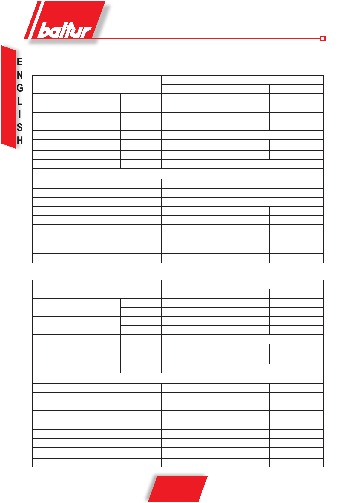
TECHNICAL DATA MODELS
BT 75 DSPG BT 100 DSPG BT 120 DSPG
FLOW RATE
I
THERMAL CAPACITY
FUEL VISCOSITY LIGHT OIL 1,5°E a/at 20°C
FAN MOTOR
TRANSFORMER VOLT 10kV-30mA 10kV-30mA 12kV 30mA
VOLTAGE 3~ 230/400V- 50 Hz
STANDARD ACCESSORIES
BURNER FIXING FLANGE N° 1 N° 2
INSULATING GASKET
ELASTIC COLLAR
STUD BOLTS N°4 M12 N°4 M16 N°4 M16
HEXAGONAL NUTS N°4 M12 N°4 M16 N°4 M16
FLAT WASHERS N°4 Ø12 N°4 Ø16 N°4 Ø16
FLEXIBLE PIPES N°2 - 1” x1" N°2 - 1” x1" N°2 - 1” x1"
NIPPLES
FILTER 1” 1” 1”
MIN. kg/h 35 45 40
MAX. kg/h 75 100 140
MIN. kW 474 533 439
MAX. kW 889 1186 1838
230/400V- 50 Hz 1,1 kW 1,5 kW 2,2 kW
N° 1
- - N° 1
N°2 - 1” x1" N°2 - 1” x1" N°2 - 1” x1"
TECHNICAL DATA MODELS
BT 180 DSPG BT 250 DSPG BT 300 DSPG
FLOW RATE
THERMAL CAPACITY
FUEL VISCOSITY GASOLIO 1,5°E a/at 20°C
FAN MOTOR
TRANSFORMER VOLT 14kV-30mA 14kV-30mA 14kV 30mA
VOLTAGE 3~ 230/400V- 50 Hz
STANDARD ACCESSORIES
BURNER FIXING FLANGE N°1 N°1 N°1
INSULATING GASKET N°1 N°1 N°1
ELASTIC COLLAR - - - - - STUD BOLTS N°4 M12 N°4 M12 N°4 - M20
HEXAGONAL NUTS N°4 M12 N°4 M12 N°4 - M20
FLAT WASHERS N°4 Ø12 N°4 Ø12 N°4 - M20
FLEXIBLE PIPES N°2 - 1”1/4 x 1"1/4 N°2 1" x 1" N°2 - 1”1/4 x 1"1/4
NIPPLES
FILTER 1”1/4 1”1/4 1”1/4
MIN. kg/h 60 74 110
MAX. kg/h 180 270 325
MIN. kW 712 873 1304
MAX. kW 2135 3186 3854
230/400V- 50 Hz 3 kW 7,5 kW 7,5 kW
- - - - - -
8 / 32
98319_200910
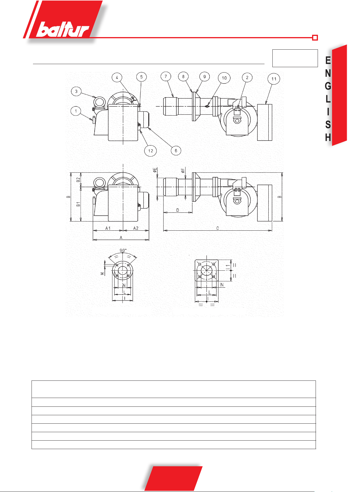
DIMENSIONS
N° 0002270035
E
N
G
L
I
S
H
BT 100 - 120 DSPG
1 - Pump
2 - Pressure regulator valve
3 - Modulator
4 - Photoresistance
5 - Ignition transformer
6 - Fan motor
MOD. A A1 A2 B B1 B2 C D E F I I1 L M N
MIN MAX Ø Ø
BT 75 DSPG 595 310 385 510 365 145 1215 130 ÷ 450 205 160 260 260 225 ÷ 300 M12 170
BT 100 DSPG 670 330 340 525 365 160 1415 210 ÷ 400 230 195 320 - 276 M16 240
BT 120 DSPG 770 390 380 610 450 160 1415 155 ÷ 500 230 195 320 - 276 M16 240
BT 180 DSPG 815 390 425 650 450 200 1700 200 ÷ 535 260 220 320 320 280÷370 M12 230
BT 250 DSPG 1000 520 480 740 580 160 1700 235 ÷ 560 260 220 320 320 280÷370 M12 230
BT 300 DSPG 1000 520 480 800 580 220 1900 245 ÷ 605 360 275 440 440 400÷540 M20 365
98319_200910
BT 75 - 180 - 250 - 300 DSPG
7 - Combustion head
8 - Insulating gasket
9 - Burner xing anges
10 - Combustion head control knob
11 - Electric board
12 - Electromagnet
9 / 32
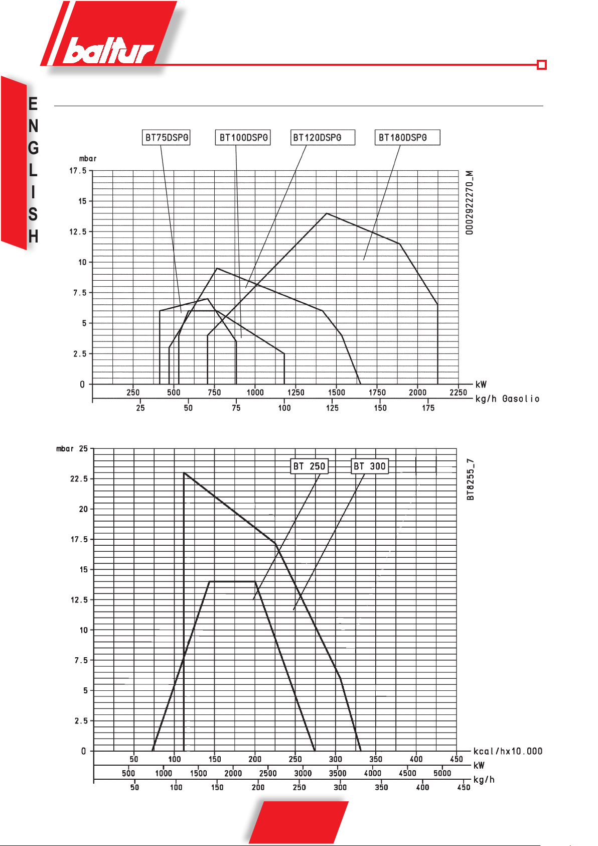
WORKING FIELD
E
N
G
L
I
S
H
10 / 32
98319_200910
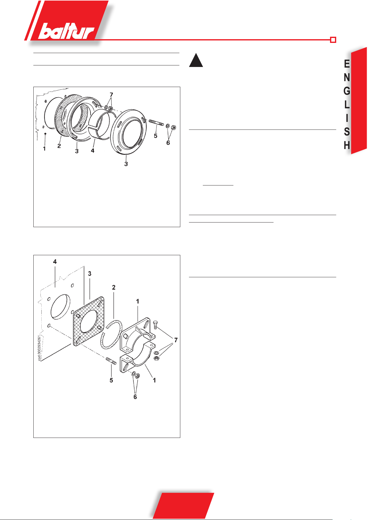
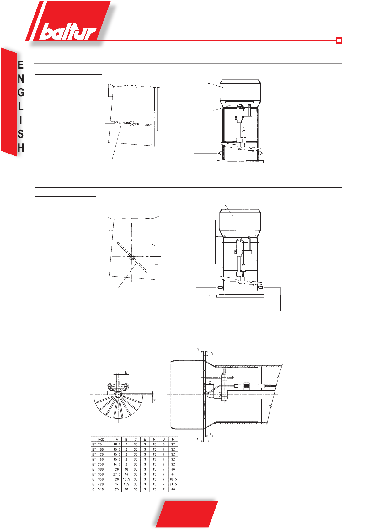
APPLICATION OF THE BURNER TO BOILER
for model BT 75 - 100 - 120 DSPG (steel xing ange)
1 - Boiler plate2 - Insulating gasket
3 - Burner xing ange
4 - Elastic collar
5 - Stud bolt
6 - Locking nut with washer
7 - Nut and washer for fastening the rst ange
for model BT 180 - 250 - 300 DSPG
When tightening the ange, it is important to do it evenly
!
so that the inner faces are parallel between them. Since
the locking system is highly efcient, do not tighten the
nuts too much. During this operation (tightening of the
ange locking nuts) keep the body of the burner lifted
so that the combustion head is kept in a horizontal
position.
N° 0002933330
FUEL FEED SYSTEM
The burner pump should receive fuel from a feed circuit which has
an ancillary pump and, in some cases, a pressure regulator capable
of modifying the pressure value from 0,2 to 1 bar (see drawing N°
0002901120).
In this case, the value of the fuel feed pressure at the burner pump
(0,2 ÷ 1 bar) should not vary when the burner is at a standstill or
when it is operating at the maximum fuel delivery required by the
boiler.
Normally it is possible to realise a circuit without a pressure regulator
as shown in drawing BT 8666/3).
The feed circuit must be realized according to drawing N°
0002901120 or to drawing BT 8666/3.
The dimension of the pipelines should be in function with their length
and with the output of the pump utilized. Our instructions cover the
basic requirements needed to ensure efcient operations. All rules
and regulations existing in the country of installation should be strictly
complied with and the local re brigade should be consulted.
E
N
G
L
I
S
H
1 Burner securing ange
2 Seam with insulating materials
3 Flange with insulating materials
4 Boiler plate
5 Stud bolts,
6 washers and nuts for astening to the boiler
7 Nuts screws and washers to fasten ange the sleeve
ELECTRICAL CONNECTIONS
The burner’s electrical connections are reduced to a minimum.
N° 0002933340
It is advisable to make all connections with exible electric wire.
The electric lines should be at an adequate distance from hot
parts.
Make sure that the electric line to which the unit will be connected
has frequency and voltage ratings suitable for the burner.
Check that the main line, the relevant switch with fuses (essential)
and the current limiter (if required) are capable of with standing the
maximum current absorbed by the burner.
For details, refer to the specic electric diagram for every burner.
11 / 32
98319_200910
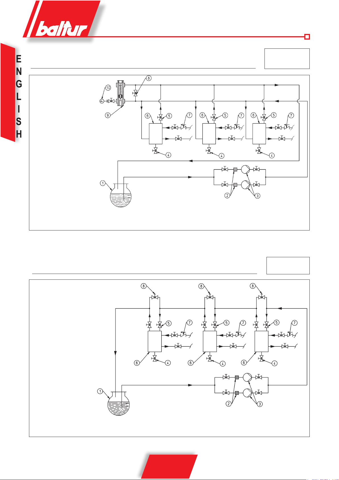
FUEL FEEDING HYDRAULIC DIAGRAM FOR ONE OR MORE LIGHT OIL BURNERS
E
WITH MAXIMUM NOMINAL VISCOSITY (5 °E at 50 °C) FROM 75 TO 300 DSPG
N
1 Main cictern
G
2 Filter
L
3 Circulation pump
4 Water and system drain
I
6 Fuel recovery and degasier
S
7 One-way valve
8 By-pass (usually closed)
H
9 Feeding circuit presure regulator
adjustment range between 0.2 and 1 bar
10 Pressure gauge (0 - 4 bar)
The combustible recovery and degasier tanks (diameter ~ 150, height ~ 400) should be installed as near as possible to the burner
and should be about 0,5 m. higher with respect to the burner's pump.
N° 0002901120
rev.: 19/02/2002
DIAGRAM OF PIPES OF FEED SYSTEM FOR LIGHT OIL BURNERS WITH MAXIMUM
NOMINAL VISCOSITY (5 °E at 50 °C)
1 Main cictern
2 Filter
3 Circulation pumps
4 Water and system drain
5 Air-gas drain usually closed
6 Fuel recovery and degasier
7 One-way valve
8 By-pass (usually closed)
The combustible recovery and degasier tanks (diameter ~ 150, height ~ 400) should be installed as near as possible to the
burner and should be about 0,5 m. higher with respect to the burner's pump.
AL BRUCIATORE
AL BRUCIATORE
N° BT 8666/3
AL BRUCIATORE
12 / 32
98319_200910
DESCRIPTION OF OPERATION WITH LIGHT OIL
(See BT 8714/2)
This is referred as a 2-stage progressive operation because the
passage from the 1st ame to the 2nd ame (from the minimum
rate to the maximum pre-established rate) takes place gradually.
The burner’s control box (cyclic relay) is connected by operating
panel switch ( I ).
The cyclic relay control box carries out the ignition programme by
starting up the fan motor and thus the pump in order to effect the
pre-ventilation and light oil pre-circulation phases.
The pressure of the air supplied by the fan must be sufcient to let
the relative pressure switch come into operation; on the contrary the
control box stops in block position. Oil from the pump reaches the
atomizer unit and is obliged to circulate within it because the passage
leading to the outward and return nozzles are closed.
This closure is carried out by “closing pins” applied to the ends of the
rods. These “pins” are pressed against by strong which are situated
at the apposite ends of the rods. The oil circulates, comes out of the
atomizer unit return and arrives at the return pressure regulator. It
passes through this and reaches the pump return and from there it
is discharged back into the return.
Oil circulation, as described above, should be carried out at a pres-
sure value slightly higher (by some bar) than the minimum pressure
at which the return pressure regulator has been set (10 ÷ 12 bar).
Duration of the pre-ventilation and oil pre-circulation phase is not
22,5 seconds, as foreseen by the control box, because it is effected
when the air shutter is in an open position. The pre-ventilation and
pre-circulation time is calculated by summing together the times of
the following manoeuvres:
the modulation motor’s opening stroke (45 seconds) +
pre-ventilation time foreseen by the control box (22,5 seconds) +
modulation motor’s closing stroke until ignition air position (about
40 seconds)
Therefore, altogether, the duration of the pre-ventilation and oil precirculation phase is about 107 seconds.
Subsequently, the control box continues carrying out the ignition
programme by connecting the ignition transformer which, in turn,
feeds the electrodes with high voltage. High voltage between the
electrodes primes the electric spark for ignition of the fuel/air mixture. 2,5 seconds after the ignition spark appears, the control box
carries voltage to the magnet which, by means of appropriate levers,
moves backwards the two rods which intercept the ow (outward
and return) of light oil to the nozzle. This moving backwards of the
rods also determines a closing of the passage (by-pass) inside the
atomizer unit.
Consequently, the pump pressure is taken to the normal value of
about 20 ÷ 22 bar.
Deviation of the two rods from the closing seat, now permits the
fuel to enter the nozzle at the pressure at which the pump has been
regulated at (20 ÷ 22 bar), and comes out of the nozzle adequately
atomized. The return pressure, which determines delivery to the
furnace, is regulated by the return pressure regulator. The value of
the ignition ow rate (minimum delivery) should be about 10 ÷ 12
bar. The atomized light oil which comes out of the nozzle is mixed
with air supplied by the fan and is then ignited by the spark of the
electrodes. Flame presence is detected by the photoresistance.
The programme proceeds and, after 5 seconds, surpasses the
“shut down” position, disconnects the ignition transformer, and then
connects the modulation circuit. The modulation motor commands
an increase in the delivery of fuel and combustion air at the same
time. The increase in fuel delivery is determined by a disk with a
varied prole which, by rotating, can determine a greater compres-
sion of the return pressure regulator spring and thus an increase
in the pressure itself.
When the return pressure increases, there is also a corresponding
increase in fuel delivery.
There should also be an adequate increase in combustion air to
meet the increase in fuel delivery. Adjustment can be carried out
at rst regulation by operating the screws which vary the prole of
the command disc of the combustion air regulator.
Fuel and combustion air delivery both increase at the same time until
they reach maximum value (light oil pressure at the return pressure
regulator is equal to about 18 ÷ 20 bar if the pressure at the pump
is at the value of 20 ÷ 22 bar).
Fuel and combustion air delivery keeps its maximum value until
the temperature of the boiler (pressure if we have a steam boiler)
approaches the set value on the thermostat (or pressure switch) of
the second stage which determines the return of the delivery regulation servomotor (fuel/air) in the apposite direction to the previous
movement thus gradually reducing the delivery of the gas oil and
of its combustion air to a minimum value.
If even with a minimum fuel and combustion air delivery a maximum
temperature is reached (pressure if we have a steam boiler), at the
set value the thermostat (pressure switch if we have a steam boiler)
determines the complete stop of the burner.
When the temperature lowers (pressure if we have a steam boiler)
below the value causing the activation of the stopping device, the
burner starts up again as described above. Under regular working
conditions, the 2nd stage thermostat (or pressure switch) detects
any variation, in the boiler load and automatically requires the
adjustment of the gas oil delivery and of its combustion air to the
delivery regulation servomotors (fuel/air).
Thus the delivery regulation system (fuel/air) reaches a balance
position corresponding to a fuel delivery and to its combustion air
delivery equal to the heat amount required by the boiler.
As an indication, it should be kept in mind that the eld of
!
variation in output obtainable with a good quality fuel is from
1 to 1/3 of the maximum output given on the rating plate.
E
N
G
L
I
S
H
Control box &
relative Programmer
LAL 1,25
Cyclic relay
Safety Time
in seconds
5
Control box specications
Pre-Ventilation & Oil
Pre-circulation Time
in seconds
22,5
98319_200910
13 / 32
Pre-ignition Time
in seconds
2,5
Post-ignition
Time
in seconds
5
Time between
1st ame & Start of
Modulation
in seconds
15
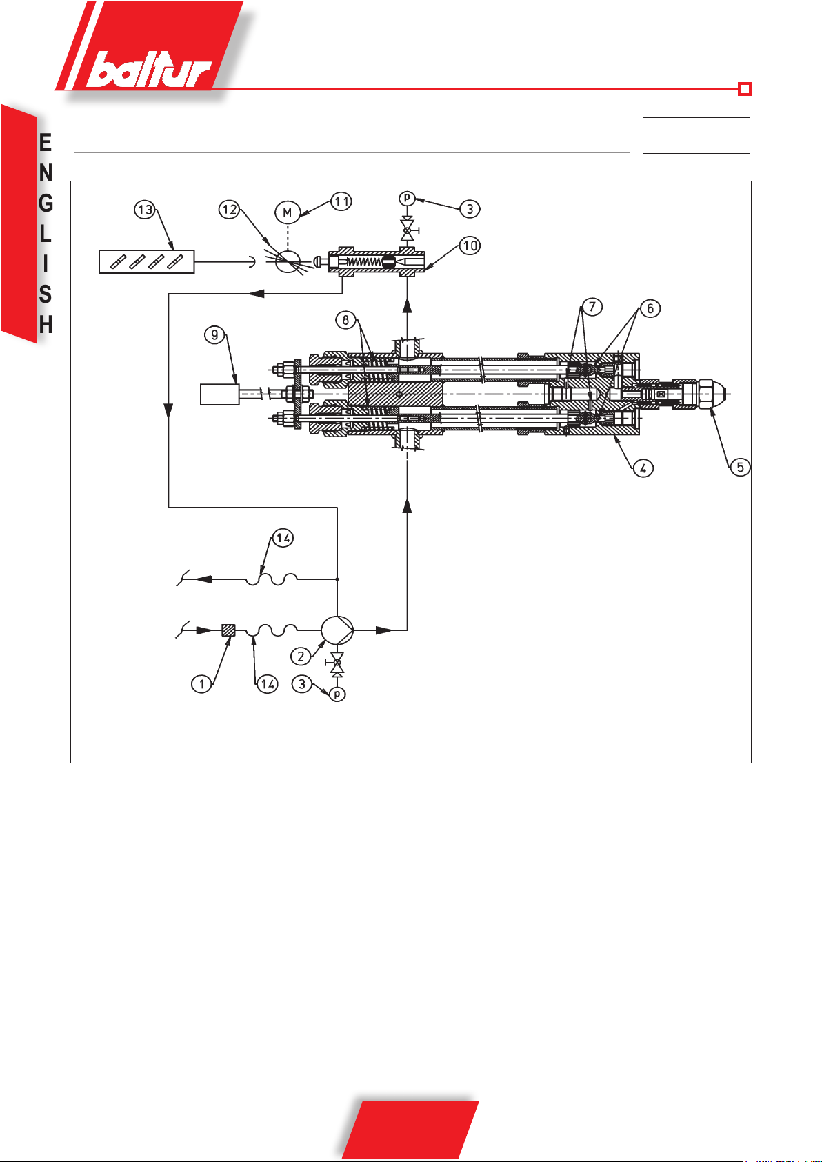
FUEL FEEDING DIAGRAM FOR BURNERS (MAGNET-NOZZLE WITHOUT PIN)
E
N
G
L
I
S
H
1 FILTER
2 BURNER PUMP
3 PRESSURE GAUGE 0 - 40 BAR
4 ATOMIZER UNIT
5 RETURN NOZZLE WITHOUT PIN
CONNECTION AT THE
FUEL FEEDING DIAGRAM FOR ONE OR
MORE BURNERS
(SEE 0002901120)
6 ROD WITH CLOSING PINS
7 BY-PASS HOLES
8 CLOUSING SPRING
9 OPENING ELECTROMAGNET
10 RETURN PRESSURE REGULATOR
11 MODULATION SERVOMOTOR
12 CONTROL DISK FOR VARIATION OF FUEL / AIR DELIERY
13 AIR REGULATION SHUTTERS
14 FLEXIBLE PIPE
N° BT 8714/2
rev.: 19/02/2002
MIN = 10-12 BAR
MAX = 18-20 BAR
14 / 32
98319_200910
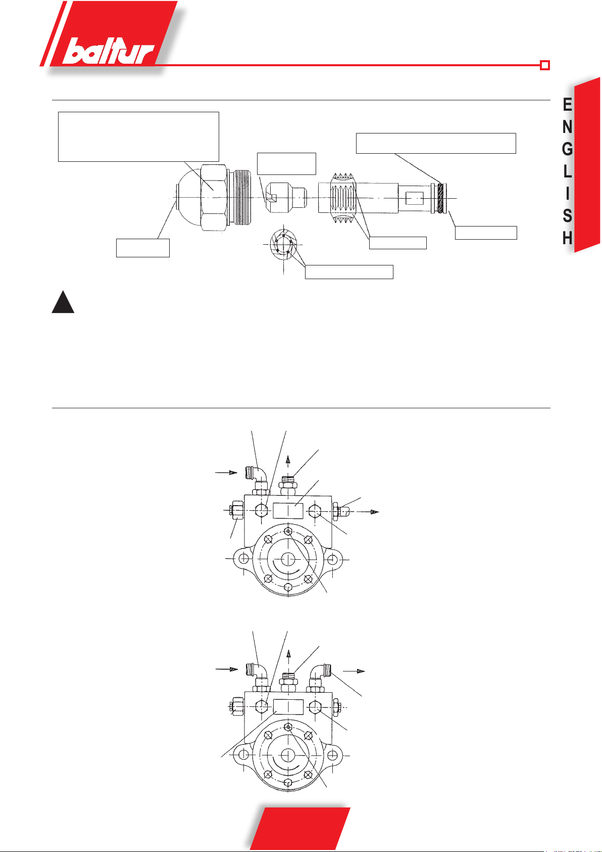
DIAGRAM OF A DISMANTLED ( C.B. ) CHARLES BERGONZO NOZZLE (WITHOUT PIN)
Nozzle ID.:
Flow rate kg/h
Spray angle (30° - 45° - 60° - 80°)
Flow ratio (1/3 = B3 - 1/5 = B5)
Air turbolence
chambre
Viton O-ring (oil and teperature resistant)
E
N
G
L
N BT 9353/1
Fuel outlet
Fuel return hole
For the nozzle to operate properly, its "return" section must never be completely closed. This is achived by regulating where the
!
burner is started up for the rst time. In practice, when the nozzle is operating at the maximum ow rate, the difference in pressure
between the "delivery" (pump pressure) and "return" (pressure at the return pressure regulator) pressure (running to and from the
nozzle) must be at least 2 ÷ 3 bar.
Example: Pump pressure 20 bar Pump pressure 22 bar
Return pressure 20 - 2 = 18 bar Return pressure 22 - 3 = 19 bar
Return pressure 20 - 3 = 17 bar Return pressure 22 - 2 = 20 bar
Fuel inlet
Fuel return
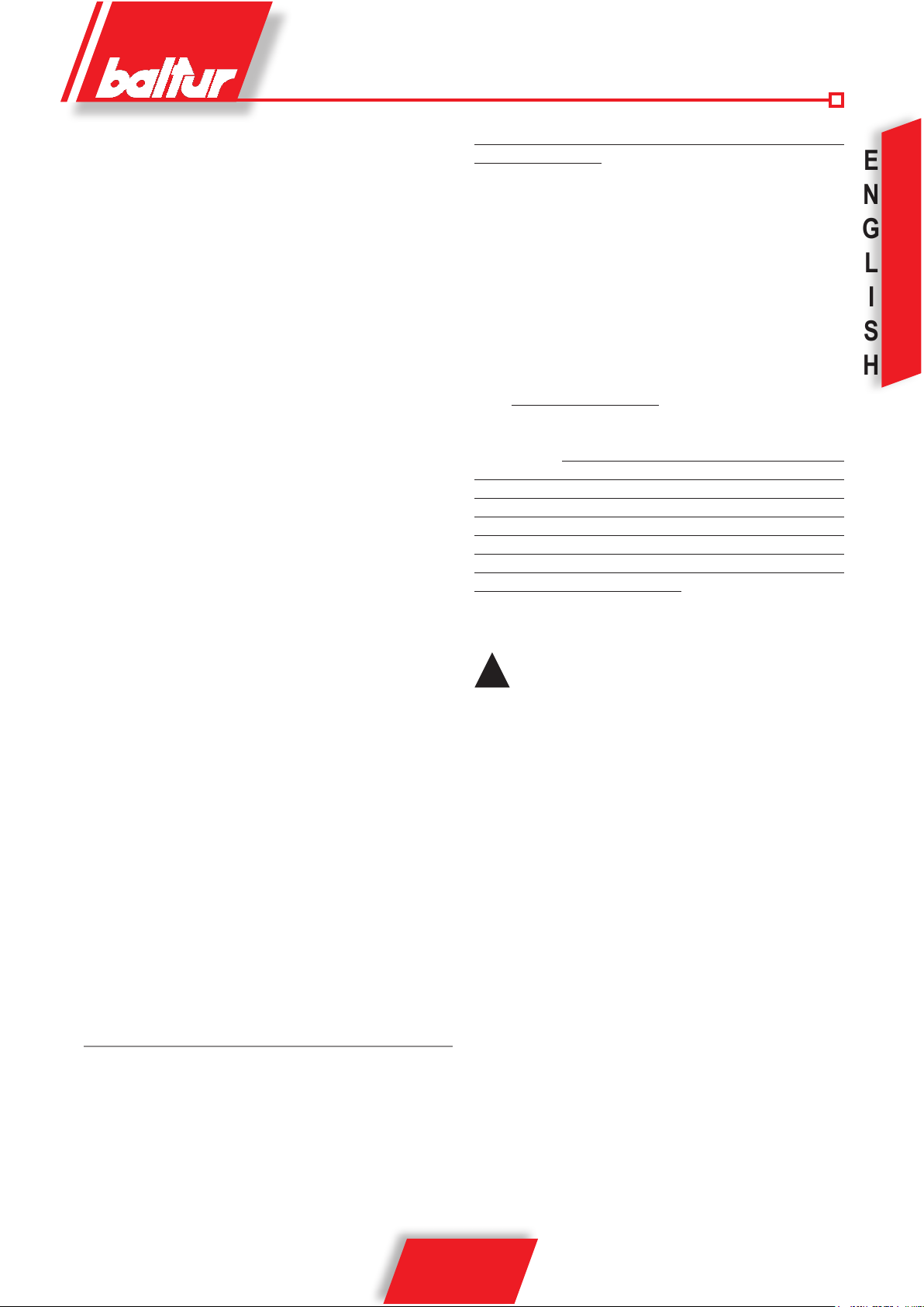
BALTUR PUMP MODEL BT.....
Suction
1/4” Vacuum-meter connection
Return
Pump plate
I
S
H
Pump pressure regulation
(20 ÷ 22 bar)
Pump pressure regulation
(20 ÷ 22 bar)
Pump plate
N° 0002900580
Suction
Delivery (nozzle)
1/4” Pressure gauge connection
Heating element seal
1/4” Vacuum-meter connection
Return
Delivery (nozzle)
1/4” Pressure gauge connection
15 / 32
98319_200910
Heating element seal

STARTING UP AND REGULATION WITH LIGHT OIL
E
1) Check that the characteristics of the nozzle (delivery and
N
G
L
I
S
H
spray angle) are suitable for the furnace (see BT 9353/1).
If not, replace it.
2) Check that there is fuel in the cistern and that it is, at least
visually; suitable for the burner.
3) Check that there is water in the boiler and that the system’s gate
valves are open.
4) Check, with absolute certainty, that the discharge of combustion
products can take place freely (boiler and chimney lock-gates
should be open).
5) Make sure that the voltage of the electric line to which the burner is to be connected, corresponds to that requested by the
manufacturer, and that the motor’s electrical connections have
been correctly prepared to match the voltage rating available.
Also are in accordance with our electric wiring diagram.
6) Make sure that the combustion head enters the furnace to the
extent specied by the boiler manufacturer. Check that the
combustion head is in the position considered necessary for
the fuel delivery required (the air passage between the disk and
the head should be considerably closed when the fuel delivery
is relatively reduced; on the other hand, when the nozzle has
a fairly high delivery, the air passage between the disk and
the head should be relatively (see chapter “Regulation of the
combustion head”).
7) Remove the protective cover from the rotating disk inserted on the modulating motor. On this disk have
been tted adjustable screws which are used to control the fuel
and the relative combustion air.
8) Put the two modulating switches in the “MIN” (minimum) and
“MAN” (manual) positions.
9) Start up the fuel supply auxiliary circuit, check its efciency and
regulate the pressure at about 1 bar (if the circuit is supplied
with a pressure regulator).
10)Remove from the pump the vacuumeter connection point plug
and then open slightly the gate valve tted on the fuel arrival
pipe. Wait until fuel comes out of the hole, without air bubbles,
and then re-close the gate valve.
11) Insert a manometer (end of the scale about 3 bar) into the vacuumeter connection point on the pump and control the value of the
pressure at which the fuel arrives at the burner pump. Insert a
manometer (and of the scale about 30 bar) into the manometer
connection point provided on the pump and control its working
pressure. Insert a manometer (end of the scale about 30 bar) into
the special connection point of the rst ame return pressure.
12) Now open all the gate valves and any other fuel interception
devices tted on the fuel pipelines.
13) Put the switch on the control panel in the “0” (open) position and
give current to the electric lines which the burner is connected
to. Check, by pressing manually on the relative relay, that the
motor rotates in the right direction. If it does not, exchange the
places of two cables of the principle line in order to invert the
sense of rotation.
14) Start operating the burner pump by pressing manually on the
relative relay until the manometer, which measures the working
pressure of the pump, indicates a slight pressure. The presence
of low pressure in the circuit conrms that lling up has taken
place.
15) Insert the switch on the control panel to give current to the control
box. If the thermostats (safety and boiler) are closed, the control
box’s programmer will be connected and will insert the burner’s
component devices according to its-established programme.The
unit starts up in this way, as described in chapter “Description
of Operations”.
16) When the burner is operating at “minimum”, proceed with regulating the air to the quantity considered
necessary to ensure efcient combustion. Tighten or loosen the
adjusting screws situated on the point of contact on the lever,
which transmits the movement to the combustion air regulation
shutter. It is preferable that the quantity of air for the “minimum”
is slightly reduced, in order to ensure a soft ignition even in the
most critical conditions.
17) After having regulated the air for the “minimum”, put the modu-
lation switches in the “MAN” (manual) and “MAX” (maximum)
positions.
18) The modulation motor starts moving; wait until the disk on which
the regulating screws have been tted, has reached an angle
of about 12° (this corresponds to the space taken up by three
screws), stop the modulation motor and return the switch to the
“0” position. Carry out a visual control of the ame and proceed,
if necessary, with regulating the combustion air by operating
as described in point 16. Subsequently, control combustion
with the appropriate instruments and modify, if necessary, the
previous regulation carried out after a visual control only. The
operation described above should be repeated progressively
(by moving forwards the disk by about 12° at a time) and modifying every time, if necessary; the fuel/air ratio during the entire
modulating run. Make sure that the increase in fuel delivery
occurs gradually and that maximum delivery is reached at the
end of the modulation run. This is necessary in order to ensure
that modulation functions with good graduality. The position of
the screws that commend the fuel may need to be modied
in order to obtain the graduality required. Maximum delivery
is obtained when the return pressure is about 2 ÷ 3 bar less
than the delivery pressure (normally 20 ÷ 22 bar). For a correct
Fuel/air ratio, the percentage of Carbon Dioxide (CO
increase with the increase delivery (from a minimum of 10% at
minimum delivery to a maximum of 13% at maximum delivery).
We advise against exceeding 13% of CO2 to avoid operating with
a rather limited excess of air which would cause a considerable
increase in smoke opacity due to unavoidable circumstances
(a variation in the atmospheric pressure; presence of dust
particles in the fan’s air ducts, etc.). Smoke opacity depends
on the type of fuel utilized (the most recent provisions indi-
cate that it should not exceed n. 2 of the Bacharach Scale).
We advise, if possible, maintaining smoke opacity below n. 2 of
the Bacharach Scale even if, as a consequence, the CO2 value
is slightly lower. The lower smoke opacity dirties the boiler less
) should
2
16 / 32
98319_200910
and therefore its average yield is normally higher even when
the CO2 value is slightly inferior. It should be remembered
that, in order to regulate properly, the water in the system
should be at the right temperature and the burner should have
been operating for at least 15 minutes. If the appropriate
instruments are not available, judgement can be based on the
colour of the ame. We advise regulating in such a way as to
obtain a ame bright orange in colour. Avoid a red ame with
smoke in it, or a white ame with an exaggerated excess of air.
After having checked the fuel/air regulation, tighten the locking
screws of the adjustable screws.
19) Now check if the modulation is functioning correctly in the
automatic mode by moving the AUT - 0 - MAN switch to the
“AUT” position and the MIN - 0 - MAX switch “0”. In this way
the modulation is connected only by means of the automatic
control of the boiler probe if we have a modulating burner or
by means of a commend coming from 2° stage thermostat or
pressure switch if we have a two progressive stage burner (BT...
DSPG).
20) Check the efciency of the ame detection device (photoresistance).The photoresistance is a ame control device and,
if the ame should be extinguished during operations, it must
be capable of intervening (this control should be made at least
one minute after start up). The burner should be capable of
blocking itself (shut down), and remaining so; if the ame does
not appear regularly during the start up phase within the time
limit preset on the control box.The shut down causes an imme-
diate interception of the fuel, the burner comes to a standstill
and the red warning light comes on. To check the efciency of
the photoresistance and of the shut down system, proceed as
follows:
a) start up the burner
b) after about one minute, extract the photoresistant cell by
pulling it out of its seat and simulate ame failure (using a
hand or a rag to close the window in the photoresistance
support). The ame should be extinguished.
c) Keep the photoresistant cell in the dark and the burner will
start up again but, as the photoresistance does not see the
light, the burner will go to shut down within the time preset
on the control box’s programme. The control box can only
be unblocked by pressing manually on the appropriate pushbutton. To check the efciency of the shut down device; carry
out this control at least twice.
High air pressure, upstream the disk, might be necessary in order to
avoid ame pulsation’s, and it is considered practically indispensable
when the burner is operating with a pressurized furnace and/or
high thermal load. It is evident from the above, that the position of
the device which regulates the air on the combustion head should
be put in such a position as to always obtain a decidedly high air
pressure value behind the disk.
It is advisable to regulate in such a way as to achieve a throttling
of the air between of the air shutter which regulates the ow to the
burner’s fan suction. Obviously these adjustments should be carried
out when the burner is operating at maximum delivery desired. In
practice, commence regulating with the combustion head in an intermediate position, start up the burner and make a rst adjustment
as previously described.
When maximum delivery desired has been reached, proceed with
correcting the position of the combustion head; move it backwards
and forwards in such a way as to obtain an air ow suitable for the
light oil delivery with the air regulation in suction considerably open.
In the combustion head is pushed forwards (which causes a reduction in the air passage between the head and the disk), avoid closing
it completely. When regulating the combustion head, proceed with
centring it perfectly with respect to the disk. It must be pointed out
that, if perfect centring with respect to the disk is not obtained, bad
combustion and excessive heating of the head could occur which
would result in its rapid deterioration.
A control can be carried out by looking through the spy hole situated
on the back of the burner; then tighten home the screws that lock
the combustion head in position.
Make sure that the ignition is correct because if the
!
regulator has been moved forward, it may happen that
the speed of the exiting air is so high that it impairs the
ignition. If this occurs, gradually move the regulator
backward until it reaches a position which allows to
have a regular ignition and set this position as nal.
Remember furthermore that for the 1° ame it is recommended to limit the amount of air to the minimum
required amount in order to have a safe ignition even
in the most complicated conditions.
E
N
G
L
I
S
H
21) Check the efciency of the boiler’s thermostats or pressure
switches (this operation should stop the burner.
REGULATION OF THE COMBUSTION HEAD
The burner is equipped with a combustion head which can be regulated (by moving it backwards or forwards) in such a way as to close
more or open more the air passage between the disk and the head.
By throttling the passage, it is possible to achieve high pressure
upstream the disk, and therefore high velocity and air turbulence for
low inputs as well. High velocity and air turbulence ensure a better
penetration in the fuel and are therefore an optimum mixture and
allow the burner to operate with good ame stability.
98319_200910
17 / 32
GENERAL DIAGRAM AIR REGULATION
E
INCORRECT REGULATION
N
G
Combustion head
L
I
S
H
CORRECT REGULATION
Combustion air inlet with
very locked shutter
Air ow large
opening
Control and xing knobs of
Combustion head
Air ow quite locked.
Attention:
Avoid complete
locking
N° BT 8608/1
combustion head
Combustion air inlet with
very opened shutter
Control and xing knobs of
combustion head
DRAWING (AS REFERENCE POINT) SHOWING THE PLACING OF NOZZLE - ELECTRODES - FLAME DISK
N° 0002931451
18 / 32
98319_200910
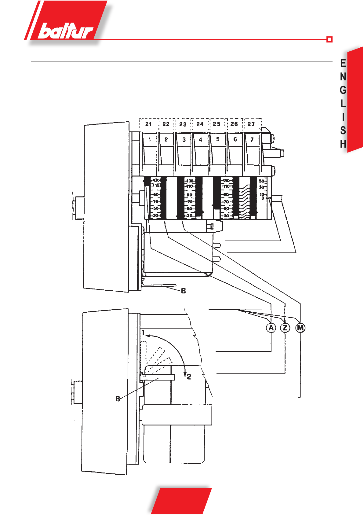
DETAILS OF THE MODULATION CONTROL MOTOR SQM 10 AND SQM 20 FOR REGULATION OF CAMS
To modify the regulation of the 3 cams utilized, operate the respective red rings ( A - Z - M ).
By pushing with enough force, in the direction desired, each red ring will rotate with respect to the reference scale.
The index of the red ring indicates on the respective reference scale the rotation angle taken up for each cam.
N° BT 8562/2
E
N
G
L
I
S
H
Reference Index
Camsshaft
Adjustable Cams
Maximum air opening
end of the run
Complete air closure
(burner not operating)
Air ignition opening
19 / 32
98319_200910
B = Insertion and disinsertion lever
motor connection Camshaft
Position 1 = Disinsertion
Position 2 = Insertion

E
N
G
L
S
H
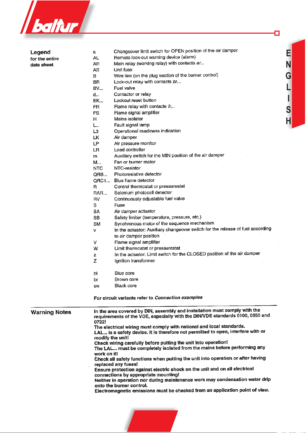
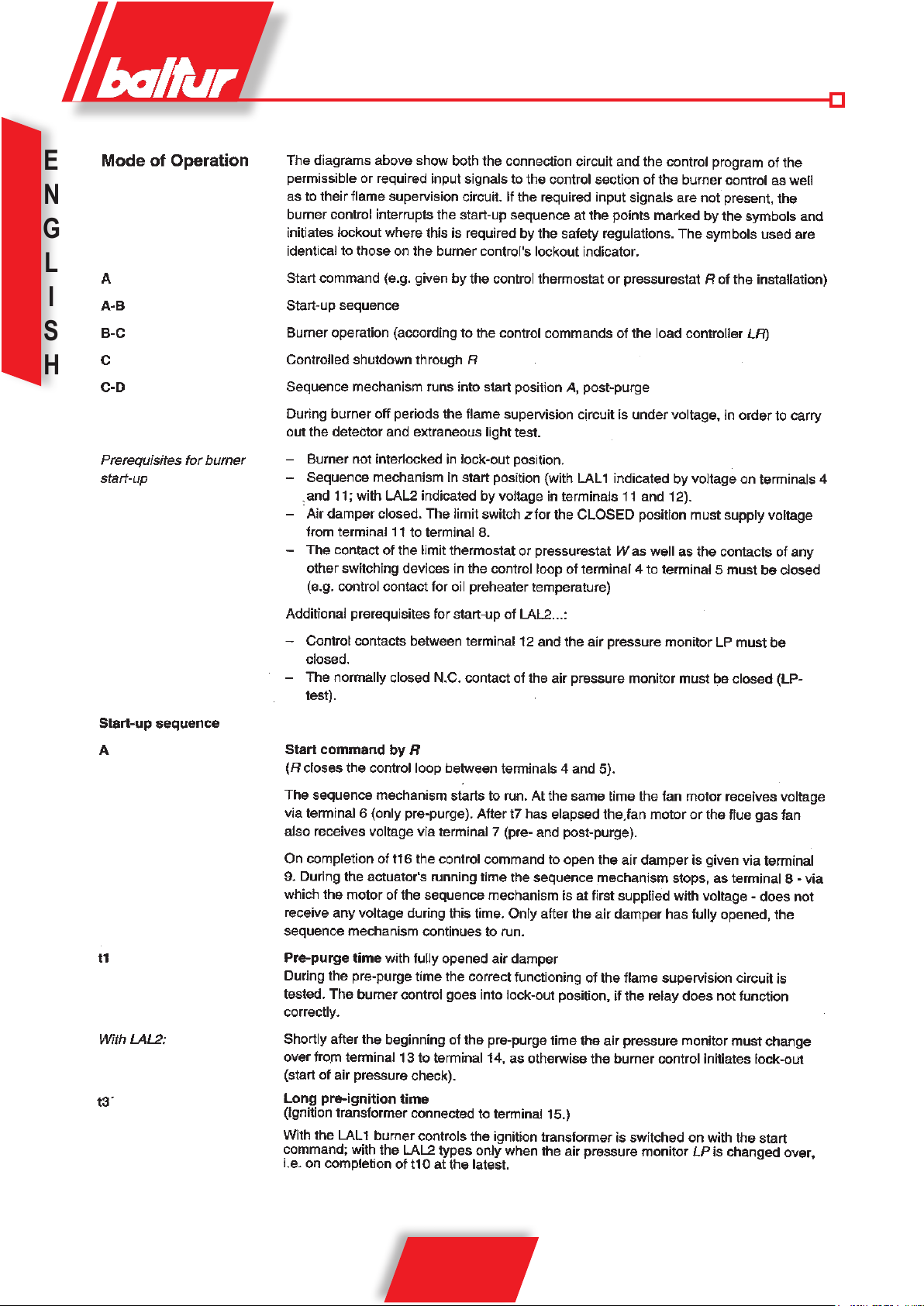
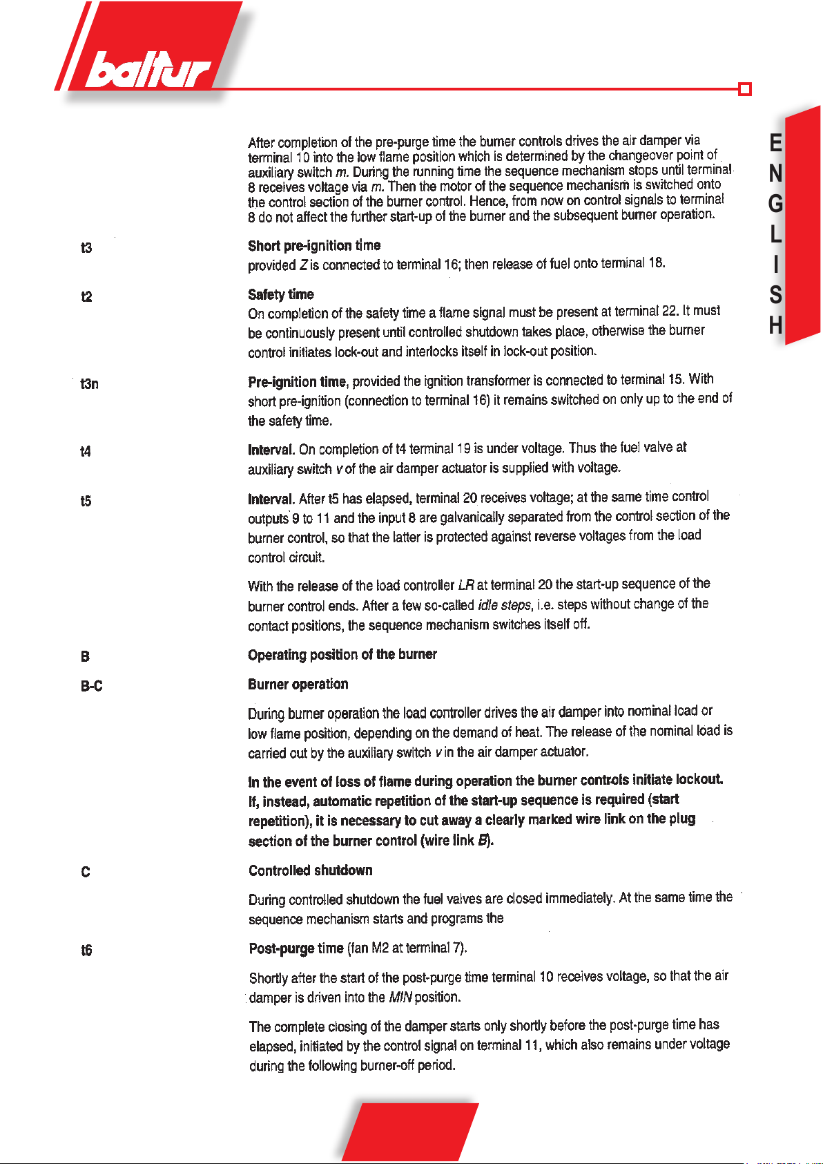
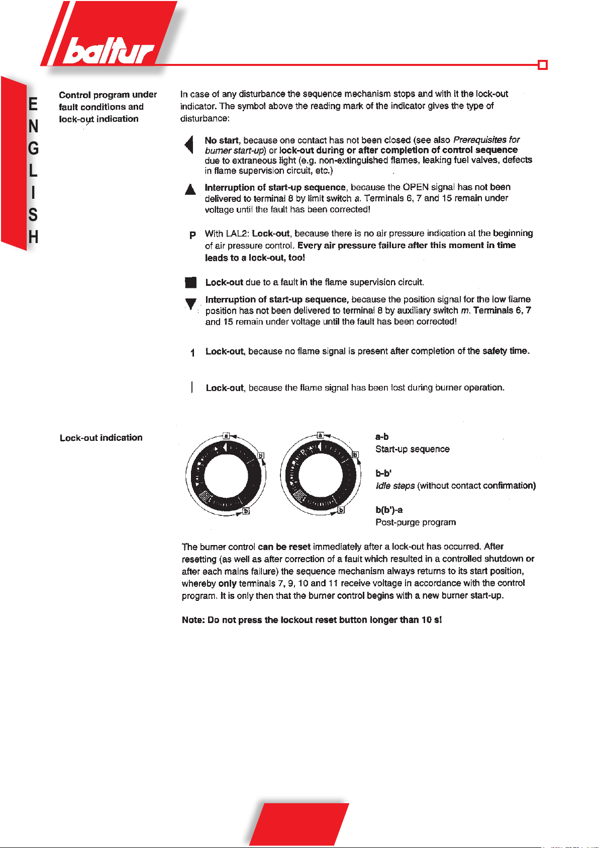
CONTROL BOX
I
20 / 32
98319_200910
E
N
G
L
S
H
I
21 / 32
98319_200910
E
N
G
L
S
H
I
22 / 32
98319_200910
E
N
G
L
S
H
I
23 / 32
98319_200910
E
N
G
L
S
H
I
24 / 32
98319_200910
E
N
G
L
S
H
I
25 / 32
98319_200910
E
N
G
L
S
H
I
26 / 32
98319_200910
E
N
G
L
S
H
I
27 / 32
98319_200910
E
N
G
L
S
H
I
28 / 32
98319_200910
 Loading...