

baltur BT 350 DSG Manual User Instructions

Manual
user instructions.
BT 350 DSG
TWO-STAGE DIESEL BURNER
ISTRUZIONI ORIGINALI (IT)
98318_201204


- Before starting to use the burner for the first time, read carefully the chapter “WARNING NOTES FOR THE USER: HOW TO USE
BALTUR S.p.A.
Via Ferrarese 10 - 44042 CENTO (Ferrara) ITALIA
Tel. 051.684.37.11 Fax 051.685.75.27/28
(International Tel. ++39.051.684.37.11 - Fax ++39.051.683.06.86)
http://www.baltur.it - http://www.baltur.com - E-MAIL info@baltur.it
THE BURNER SAFELY” in this instruction manual, which is an integral and essential part of the product.
- Read carefully the instructions before starting the burner and servicing it.
- The works on the burner and on the system should be carried out only by qualified personnel.
- The system power supply must be disconnected before starting working. If the works are not carried out correctly it is possible to
cause dangerous accidents.
Declaration of Conformity
We declare that our products
BPM...; BGN…; BT…; BTG…; BTL…; TBML...; Comist…;
GI…; GI…Mist; Minicomist…; PYR…; RiNOx…; Spark...;
Sparkgas...; TBG...;TBL...; TBML ...; TS…; IBR...; IB...
(Variant: … LX, for low NOx emissions)
Description:
forced air burners of liquid, gaseous and mixed fuels for residential and
industrial use meet the minimum requirements of the European Directives:
2009/142/CE ..............................................(D.A.G.)
2004/108/CE ...............................................(C.E.M.)
2006/95/CE .................................................(D.B.T.)
2006/42/CE ................................................(D.M.)
and conform to European Standards:
UNI EN 676:2008 (gas and combination, gas side)
UNI EN 267:2002 (diesel and combination, diesel side)
These products are therefore marked:
0085
Dr. Riccardo Fava
18/11/2010
TECHNICAL SPECIFICATIONS ......................................................................................................................................................................................4
PRELIMINARY REMARKS FOR A PROPER INSTALLATION .......................................................................................................................................6
FIXING THE BURNER TO THE BOILER ........................................................................................................................................................................ 6
ELECTRICAL CONNECTIONS .......................................................................................................................................................................................7
FUEL PIPELINES (DIESEL) ............................................................................................................................................................................................7
AUXILIARY PUMP ........................................................................................................................................................................................................... 7
OPERATION DESCRIPTION ..........................................................................................................................................................................................9
IGNITION AND ADJUSTMENT ....................................................................................................................................................................................... 11
ADJUSTING THE DISTANCE BETWEEN DISK AND NOZZLE - ADJUSTING THE AIR ON THE COMBUSTION HEAD .........................................12
CHECKS - USING THE BURNER ...................................................................................................................................................................................12
MAINTENANCE ............................................................................................................................................................................................................... 13
DESCRIPTION OF THE TWO-STAGE BURNER OPERATION ....................................................................................................................................13
TROUBLESHOOTING ..................................................................................................................................................................................................... 14
BALTUR PUMP MODEL BT.... .........................................................................................................................................................................................17
NOZZLE FLOW-RATE TABLE FOR DIESEL FUEL .......................................................................................................................................................18
WIRING DIAGRAM ......................................................................................................................................................................................................... 20
Managing Director / CEO
1 / 22
98318_201204

accordance with current regulations and in any case suf cient to ensure
ventilation openings for the room where a burner or a boiler is installed
• If it is decided not to use the burner any more, the following actions must
• Check that the person who carried out the installation of the burner xed
b) Adjust the combustion air ow to obtain combustion yield of at least
• If the burner repeatedly stops in lock-out, do not keep trying to manually
WARNING NOTES FOR THE USER HOW TO USE THE BURNER SAFELY
FOREWORD
These warning notes are aimed at ensuring the safe use of the components of heating systems for civil use and the production of hot water.
They indicate how to act to avoid the essential safety of the components
being compromised by incorrect or erroneous installation and by improper
or unreasonable use. The warning notes provided in this guide also seek
to make the consumer more aware of safety problems in general, using
necessarily technical but easily understood language. The manufacturer
is not liable contractually or extra contractually for any damage caused
by errors in installation and in use, or where there has been any failure to
follow the manufacturer’s instructions.
GENERAL WARNING NOTES
• The instruction booklet is an integral and essential part of the product
and must be given to the user. Carefully read the warnings in the booklet as they contain important information regarding safe installation,
use and maintenance. Keep the booklet to hand for consultation when
needed.
• Equipment must be installed in accordance with current regulations,
with the manufacturer’s instructions and by quali ed technicians. By
the term ‘quali ed technicians’ is meant persons that are competent in
the eld of heating components for civil use and for the production of
hot water and, in particular, assistance centres authorised by the manufacturer. Incorrect installation may cause damage or injury to persons,
animals or things. The manufacturer will not in such cases be liable.
• After removing all the packaging make sure the contents are complete
and intact. If in doubt do not use the equipment and return it to the
supplier. The packaging materials (wooden crates, nails, staples, plastic
bags, expanded polystyrene, etc.) must not be left within reach of children as they may be dangerous to them. They should also be collected
and disposed on in suitably prepared places so that they do no pollute
the environment.
• Before carrying out any cleaning or maintenance, switch off the equi-
pment at the mains supply, using the system’s switch or shut-off systems.
• If there is any fault or if the equipment is not working properly, de-ac-
tivate the equipment and do not attempt to repair it or tamper with it
directly. In such case get in touch with only quali ed technicians. Any
product repairs must only be carried out by BALTUR authorised assistance centres using only original spare parts. Failure to act as above
may jeopardise the safety of the equipment. To ensure the ef ciency
and correct working of the equipment, it is essential to have periodic
maintenance carried out by quali ed technicians following the manufacturer’s instructions.
• If the equipment is sold or transferred to another owner or if the owner
moves and leaves the equipment, make sure that the booklet always
goes with the equipment so it can be consulted by the new owner and/
or installer.
• For all equipment with optionals or kits (including electrical), only origi-
nal accessories must be used.
BURNERS
• This equipment must be used only for its expressly stated use: applied
to boilers, hot air boilers, ovens or other similar equipment and not
exposed to atmospheric agents. Any other use must be regarded as
improper use and hence dangerous.
• The burner must be installed in a suitable room that has ventilation in
correct combustion
• Do not obstruct or reduce the size of the burner’ air intake grills or the
or dangerous mixtures of toxic and explosive gases may form.
• Before connecting the burner check that the details on the plate correspond to those of the utility supplies (electricity, gas, light oil or other
fuel).
• Do not touch hot parts of the burner. These, normally in the areas near
to the ame and any fuel pre-heating system, become hot when the
equipment is working and stay hot for some time after the burner has
stopped.
be performed by quali ed technicians:
a) Switch off the electrical supply by disconnecting the power cable from
the master switch.
b) Cut off the fuel supply using the shut-off valve and remove the control
wheels from their position.
c) Render harmless any potentially dangerous parts.
Special warning notes
it securely to the heat generator so that the ame is generated inside
the combustion chamber of the generator itself.
• Before starting up the burner, and at least once a year, have quali ed
technicians perform the following operations:
a) Set the burner fuel capacity to the power required by the heat ge-
nerator.
the minimum set by current regulations.
c) Carry out a check on combustion to ensure the production of no-
xious or polluting unburnt gases does not exceed limits permitted
by current regulations.
d) Check the adjustment and safety devices are working properly.
e) Check the ef ciency of the combustion products exhaust duct.
f) Check at the end of the adjustments that all the adjustment devices
mechanical securing systems are properly tightened.
g) Make sure that the use and maintenance manual for the burner is
in the boiler room.
reset but call a quali ed technicians to sort out the problem.
• The running and maintenance of the equipment must only be carried
out by quali ed technicians, in compliance with current regulations.
2 / 22
98318_201204

equipment or dangerous situations may arise with the build up of toxic
It should be pointed out that high ef ciency boilers and similar discharge
In the above situation, traditional ues (in terms of their diameter and heat
insulation) may be suitable because the signi cant cooling of the combustion
products in these permits temperatures to fall even below the condensation
point. In a ue that works with condensation there is soot at the point the
exhaust reaches the atmosphere when burning light oil or heavy oil or the
presence of condensate water along the ue itself when gas is being burnt
(methane, LPG, etc.). Flues connected to high ef ciency boilers and similar
must therefore be of a size (section and heat insulation) for the speci c use
WARNING NOTES FOR THE USER HOW TO USE THE BURNER SAFELY
ELECTRICAL SUPPLY
• The equipment is electrically safe only when it is correctly connected to an
ef cient ground connection carried out in accordance with current safety
regulations. It is necessary to check this essential safety requirement.
If in doubt, call for a careful electrical check by a quali ed technicians,
since the manufacturer will not be liable for any damage caused by a
poor ground connection.
• Have quali ed technicians check that the wiring is suitable for the
maximum power absorption of the equipment, as indicated in the technical
plate, making sure in particular that the diameter of cables is suf cient
for the equipment’s power absorption.
• Adapters, multiple plugs and extension cables may not be used for the
equipment’s power supply.
• An ominpolar switch in accordance with current safety regulations is
required for the mains supply connection.
• The electrical supply to the burner must have neutral to ground
connection. If the ionisation current has control with neutral not to ground
it is essential to make a connection between terminal 2 (neutral) and the
ground for the RC circuit.
• The use of any components that use electricity means that certain
fundamental rules have to followed, including the following:
- do not touch the equipment with parts of the body that are wet or damp
or with damp feet
- do not pull on electrical cables
- do not leave the equipment exposed to atmospheric agents (such as
rain or sun etc.) unless there is express provision for this.
- do not allow the equipment to be used by children or inexpert
persons.
• The power supply cable for the equipment not must be replaced by the
user. If the cable gets damaged, switch off the equipment, and call only
on quali ed technicians for its replacement.
• If you decide not to use the equipment for a while it is advisable to switch
off the electrical power supply to all components in the system that use
electricity (pumps, burner, etc.).
GAS, LIGHT OIL, OR OTHER FUEL SUPPLIES
General warning notes
• Installation of the burner must be carried out by quali ed technicians
and in compliance with current law and regulations, since incorrect
installation may cause damage to person, animals or things, for which
damage the manufacturer shall not can be held responsible.
• Before installation it is advisable to carry out careful internal cleaning
of all tubing for the fuel feed system to remove any residues that could
jeopardise the proper working of the burner.
• For rst start up of the equipment have quali ed technicians carry out
the following checks:
• If you decide not to use the burner for a while, close the tap or taps that
supply the fuel.
Special warning notes when using gas
• Have quali ed technicians check the following:
a) that the feed line and the train comply with current law and
regulations.
b) that all the gas connections are properly sealed.
• Do not use the gas pipes to ground electrical equipment.
• Do not leave the equipment on when it is not in use and always close
the gas tap.
• If the user of is away for some time, close the main gas feed tap to the
burner.
• If you smell gas:
a) do not use any electrical switches, the telephone or any other object
that could produce a spark;
b) immediately open doors and windows to create a current of air that
will purify the room;
c) close the gas taps;
d) ask for the help of quali ed technicians.
• Do not block ventilation openings in the room where there is gas
and explosive mixtures.
FLUES FOR HIGH EFFICIENCY BOILERS AND SIMILAR
combustion products (fumes) at relatively low temperatures into the ue.
to avoid such problems as those described above.
3 / 22
98318_201204
TECHNICAL SPECIFICATIONS
FLOW RATE
HEATING CAPACITY
FUEL VISCOSITY
FAN MOTOR
IGNITION TRANSFORMER
VOLTAGE 3N ~ 400 V - 50 Hz
MIN Kg/h
MAX Kg/h
MIN kW
MAX kW
DIESEL
FUEL
50Hz
VOLT
BT 350 DSG
115
350
1364
4151
1.5°E - 20°C
9.2 kW - 2910 r.p.m.
14 kV - 30mA - 230V - 50Hz
STANDARD ACCESSORIES
BT 350 DSG
BURNER COUPLING FLANGE No. 1
INSULATING GASKET No. 2
STUD BOLTS No. 4 - M20
HEXAGONAL NUTS No. 4 - M20
FLAT WASHERS N° 4 - M 20
FLEXIBLE PIPES No.2 - 1” ¼ L 1500
FILTER 1”¼
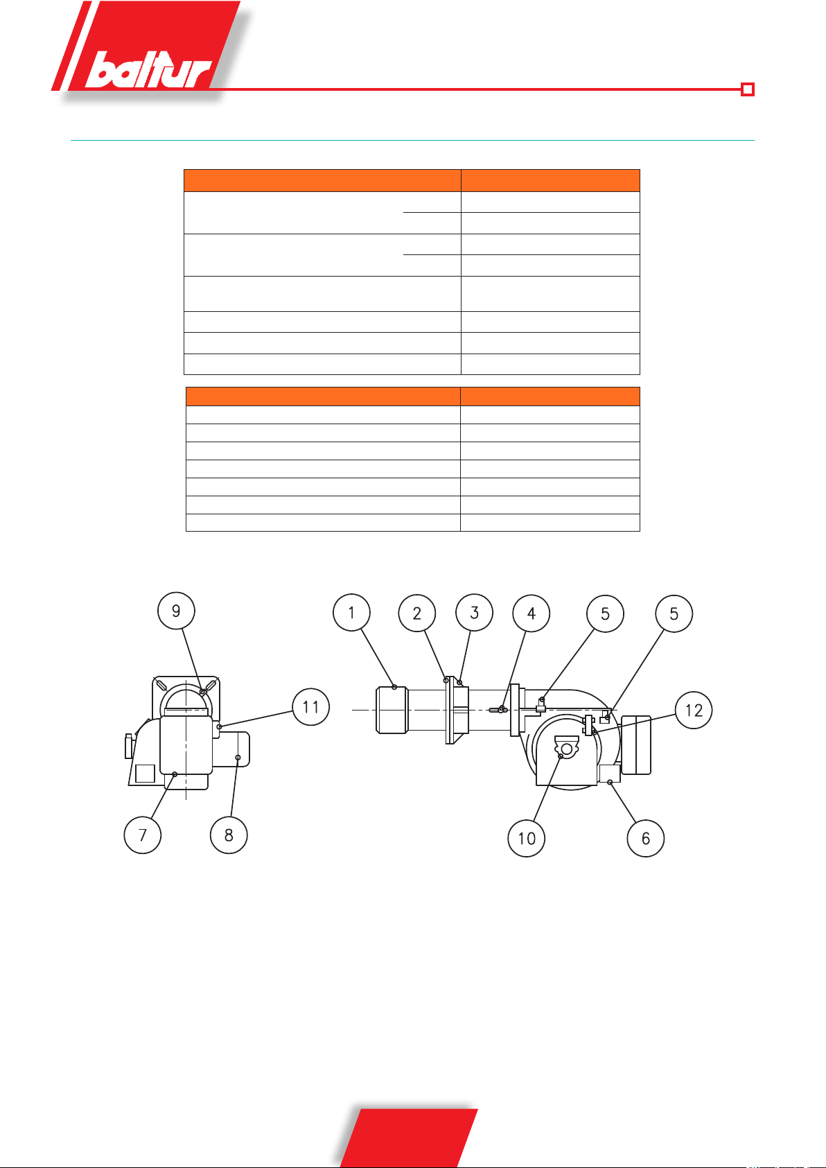
1) Combustion head
2) Insulating gasket
3) Burner coupling flange
4) Combustion head adjustment knob
5) Solenoid valves
6) Air adjustment servomotor
7) Electrical panel
8) Fan motor
9) photocell
10) Pump
11) Ignition transformer
12) Pressure control valve
4 / 22
98318_201204
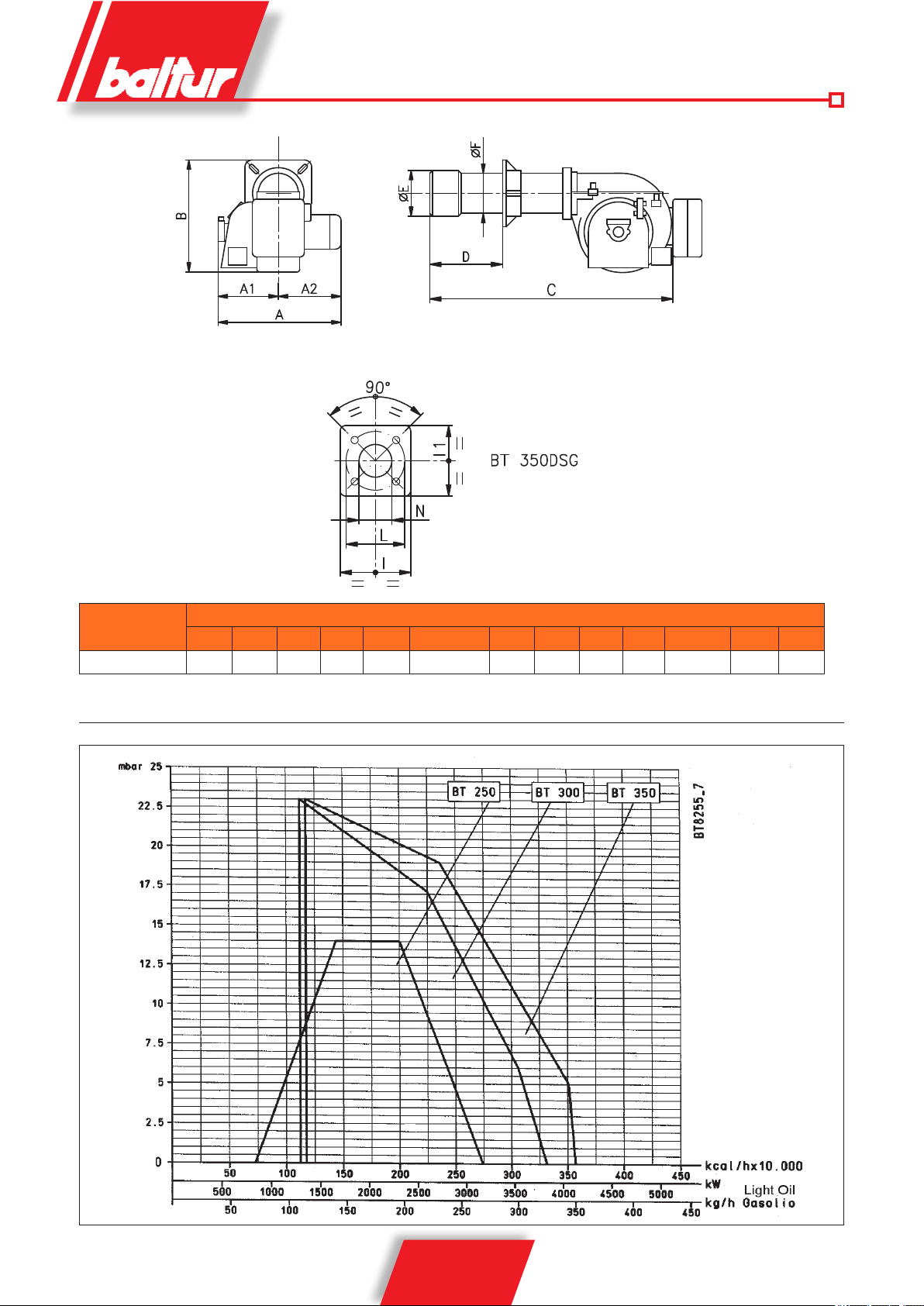
MOD.
BT 350 DSG 1050 525 525 920 1960 350 ÷ 560 360 275 440 440 400÷540 M 20 365
G A1 A2 B C D E Ø FØ E I1 L M H
OVERALL DIMENSIONS
OPERATING RANGE
5 / 22
98318_201204
PRELIMINARY REMARKS FOR A PROPER
INSTALLATION
Before proceeding with the installation make sure that:
1) The chimney (cross section and height) complies with the boiler
manufacturer’s instructions and legal provisions.
2) Where a refractory lining needs to be made for the combustion
chamber (if the type of boiler requires it) then, it is necessary
to make it according to the specific instructions of the boiler
manufacturer.
3) The burner power supply should be arranged as indicated in
our diagram and the electrical connections on the burner should
be pre-set for the mains voltage.
4) The fuel pipelines must comply with our diagrams.
5) The nozzle or the nozzles fitted on the burner should be suitable
for the boiler capacity; replace them with others, if necessary.
Under no circumstances should the the delivered quantity of
fuel exceed the maximum amount required by the boiler and
the max. amount permitted for the burner. Bear in mind that
the combustion head has been designed for nozzles with a 45°
spray angle. There are only special cases where nozzles can
be fitted with a different spray angle; in these cases, however,
make sure that the nozzle with a different spray angle will not
cause any problems (flame separation, disk or combustion head
fouling, violent ignition, etc.).
6) When removing the protective plastic cap from the nozzle seat
be careful because if the sealing surface is indented (a light
scoring would be enough) it will cause fuel dripping.
7) Make sure that the burner head enters the combustion chamber
according to the boiler manufacturer’s instructions.
8) Before connecting the flexible pipes, remove the protective
plastic caps inserted in the pump fittings.
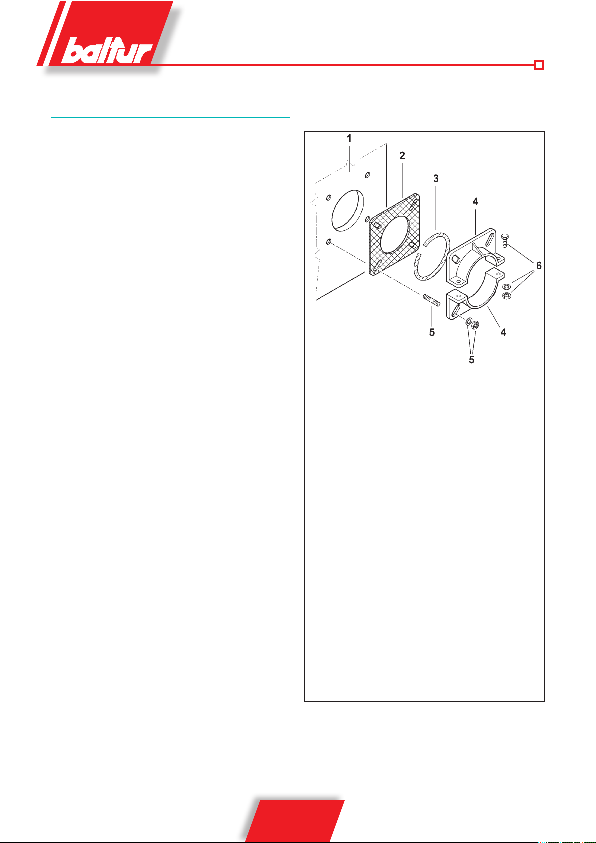
FIXING THE BURNER TO THE BOILER
0002934880
1 - Boiler plate
2 - Flange in insulating material
3 - Seam in insulating material
4 - Burner coupling flange
5 - Stud bolts, washers and nuts for fastening to the boiler
6 - Nuts screws and washers to fasten the flange to the sleeve
ASSEMBLING THE HEAD UNIT
Disassemble the end part of the combustion head to insert the
insulating flange 2 between the burner and the boiler plate 1.
a) Adjust the position of the coupling flange 4 by loosening
the screws 6 so that the combustion head penetrates into
the furnace to the extent recommended by the generator
manufacturer.
b) Place the insulating gasket 3 on the sleeve.
c) Fasten the head unit to the boiler 1 by means of the stud
d) Completely seal the gap between the burner sleeve and
6 / 22
98318_201204
bolts, washers and the nuts provided 5.
the hole in the refractory material inside the boiler door with
suitable material.
 Loading...