

Page 1
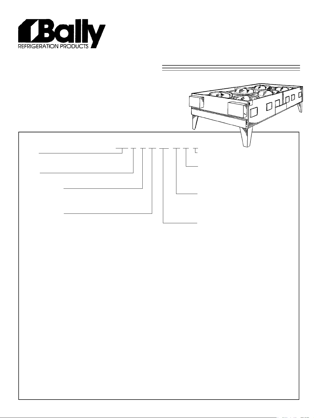
BVC Direct Drive
Air-Cooled
Condenser
PRODUCT DATA &
INSTALLATION
Bulletin B50-BVC-PDI-10
1068833
Model
BVC = Bally Vertical air flow Condenser
BCH = Bally Horizontal air flow Condenser
Tubing
1 = 3/8 OD smooth 2 = 1/2 OD smooth
Motor & Fan Type
A = 30” fan with 850 RPM motor (Standard)
B = 30” fan with 550 RPM motor
C = 30” fan with 1140 RPM motor
Fan Configuration
First number = number of fans wide
Second number = number of fans in length
26 = 2 fans wide x 6 fans length (total 12 fans)
11 = 1 fan wide x 1 fan length (total 1 fan)
One to Twelve Fan Motors
NOMENCLATURE
BVC 2 A 26 206 A - T3 C
Generation
C = Latest series (A, B older series)
Electrical Code
S2 = 208-230/1/60 S6 = 200-220/1/50
T3 = 208-230/3/60 T7 = 200-220/3/50
T4 = 460/3/60 T9 = 380-400/3/50
T5 = 575/3/60
Fin Material & Spacing
A = Aluminum 12 FPI (Standard), B = 10, C = 8
D = Gold Coat Alum 12 FPI, E = 10, F = 8
G = Copper 12 FPI, H = 10, J = 8
K = Heresite Coat Alum 12 FPI, L = 10, M = 8
Nominal Capacity (Tons - THR)
Rated at 25
12” FPI, smooth tubing, 0° Subcooling, Sea Level, 60 Hz
o
F (14 oC) TD, 30” Fan / 850 RPM Motor,
CONTENTS
PAGE
SPECIFICATIONS
Nomenclature........................................... Front
850 RPM Data:
Capacity, General Specs, Elec. Specs... 2-5
Dimensional Data...................................... 6, 7
Wiring Data.............................................. 8-11
550 RPM Data:
Capacity, General Specs, Elec. Specs... 12-15
1140 RPM Data:
Capacity, General Specs, Elec. Specs.... 16-19
DESIGN & SELECTION
Condenser Theory..................................... 20
Glossary of Terms..................................... 21, 22
Condenser Selection & Worksheets............ 23-29
Low Ambient Operation.............................. 30-34
INSTALLATION
Inspection, Location & Placement............... 35
Piping & Wiring......................................... 36
System Check & Maintenance................... 37
Service Parts............................................ 38
Project Information.................................... Back
• THERMOSPAN
TM
coil design feature eliminates
tube failure on tube sheets.
• Standard 850 RPM quiet low speed dual
voltage (230/460) fan motors with male electrical
plug, moisture slinger, and rainshield for complete
weather protection.
• Optional 550 ultra low and 1140 RPM high
speed motors available.
• Rugged heavy-gauge galvanized steel rail
motor mounts/support.
• All fan sections individually baffled with full
height partitions, and clean-out panels.
• Complete selection of electrical fan cycling and
speed control options.
• Heavy-gauge galvanized steel cabinet
construction assembled with zinc plated huck
bolts supported on heavy-duty legs.
Page 2
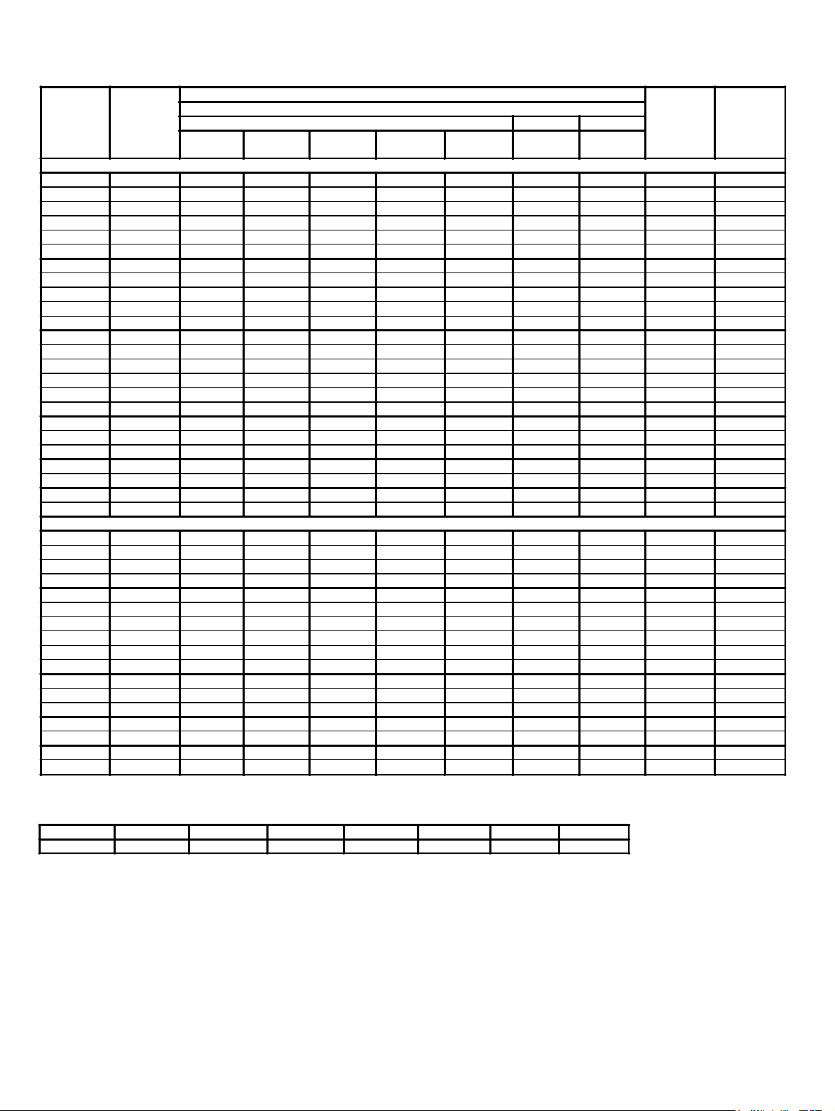
CAPACITY DATA - 850 RPM MODELS - R22
BVC
MODEL
NUMBER
007
009
010
011
012
013
017
019
022
024
027
029
034
037
041
043
048
056
063
068
079
085
095
103
039
045
049
054
058
067
073
081
086
096
112
126
137
158
172
190
206
TOTAL HEAT OF REJECTION CAPACITY (MBH)
Fan Rows
1°F
(0.56°C)
1 x 1 3.165 31.7 47.5 63.3 95.0 2.912 2.595 7 0.45
1 x 1 4.135 41.4 62.0 82.7 124 3.846 3.515 8 0.52
1 x 1 4.655 46.6 69.8 93.1 140 4.329 3.957 9 0.52
1 x 1 5.365 53.7 80.5 107 161 5.097 4.721 12 0.45
1 x 1 5.875 58.8 88.1 118 176 5.581 5.170 12 0.49
1 x 1 6.465 64.7 97.0 129 194 6.336 5.948 15 0.43
1 x 2 8.265 82.7 124 165 248 7.686 7.025 14 0.59
1 x 2 9.265 92.7 139 185 278 8.616 7.875 18 0.51
1 x 2 10.74 107 161 215 322 10.20 9.447 24 0.45
1 x 2 11.77 118 176 235 353 11.18 10.35 24 0.49
1 x 2 12.94 129 194 259 388 12.68 11.90 30 0.43
1 x 3 13.97 140 209 279 419 12.90 11.87 27 0.52
1 x 3 16.07 161 241 321 482 15.26 14.14 36 0.45
1 x 3 17.64 176 265 353 529 16.75 15.52 36 0.49
1 x 3 19.40 194 291 388 582 19.01 17.85 45 0.43
1 x 3 20.64 206 310 413 619 19.61 18.17 36 0.57
1 x 3 23.01 230 345 460 690 22.55 21.17 45 0.51
1 x 4 26.34 263 395 527 790 24.50 22.39 22 1.20
1 x 4 30.29 303 454 606 909 28.77 26.65 30 1.01
1 x 4 32.55 326 488 651 977 31.90 29.95 37 0.88
1 x 5 37.95 379 569 759 1138 36.05 33.39 30 1.26
1 x 5 40.70 407 610 814 1221 39.88 37.44 37 1.10
1 x 6 45.54 455 683 911 1366 43.26 40.07 30 1.52
1 x 6 48.84 488 733 977 1465 47.85 44.93 37 1.32
2 x 2 18.60 186 279 372 558 17.30 15.81 36 0.52
2 x 2 21.47 215 322 429 644 20.39 18.89 48 0.45
2 x 2 23.50 235 353 470 705 22.33 20.68 48 0.49
2 x 2 25.84 258 388 517 775 25.32 23.77 60 0.43
2 x 3 27.90 279 419 558 837 25.95 23.72 54 0.52
2 x 3 32.17 322 482 643 965 30.56 28.31 72 0.45
2 x 3 35.24 352 529 705 1057 33.47 31.01 72 0.49
2 x 3 38.77 388 581 775 1163 37.99 35.66 90 0.43
2 x 3 41.29 413 619 826 1239 39.22 36.33 72 0.57
2 x 3 46.02 460 690 920 1381 45.10 42.34 90 0.51
2 x 4 53.89 539 808 1078 1617 50.11 45.80 45 1.20
2 x 4 60.57 606 909 1211 1817 57.54 53.30 60 1.01
2 x 4 65.99 660 990 1320 1980 64.67 60.71 75 0.88
2 x 5 75.90 759 1138 1518 2277 72.10 66.79 60 1.26
2 x 5 82.50 825 1237 1650 2475 80.85 75.90 75 1.10
2 x 6 91.08 911 1366 1822 2732 86.52 80.15 60 1.52
2 x 6 98.99 990 1485 1980 2970 97.01 91.07 75 1.32
10°F
(5.56°C)
TEMPERATURE DIFFERENCE (TD)
12 FPI 10 FPI 8 FPI
15°F
(8.3°C)
20°F
(11.1°C)
Single Row Models
Double Row Models
30°F
(16.7°C)
1°F
(0.56°C)
1°F
(0.56°C)
Maximum
No. of
Feeds
MBH
@ 1° F TD
Per Feed
(12 FPI)
Correction Factors for Other refrigerants - Use R22 Values Multiplied By
R134a R12 R507 R404A R407A R407B R502 R407C
0.94 0.95 0.97 0.97 0.97 0.97 0.98 1.00
NOTES: (1) Above capacity data based on 0°F subcooling and at sea level.
(2) TD = Condensing temperature - ambient temperature
(3) Standard fin spacing is 12 FPI except models 056 and 112 (13 FPI).
(4) For High Altitude applications apply the following correction factors:
0.94 for 2000 feet, 0.88 for 4000 feet and 0.81 for 6000 feet.
(5) For 50Hz capacity multiply by 0.92.
- 2 -
Page 3
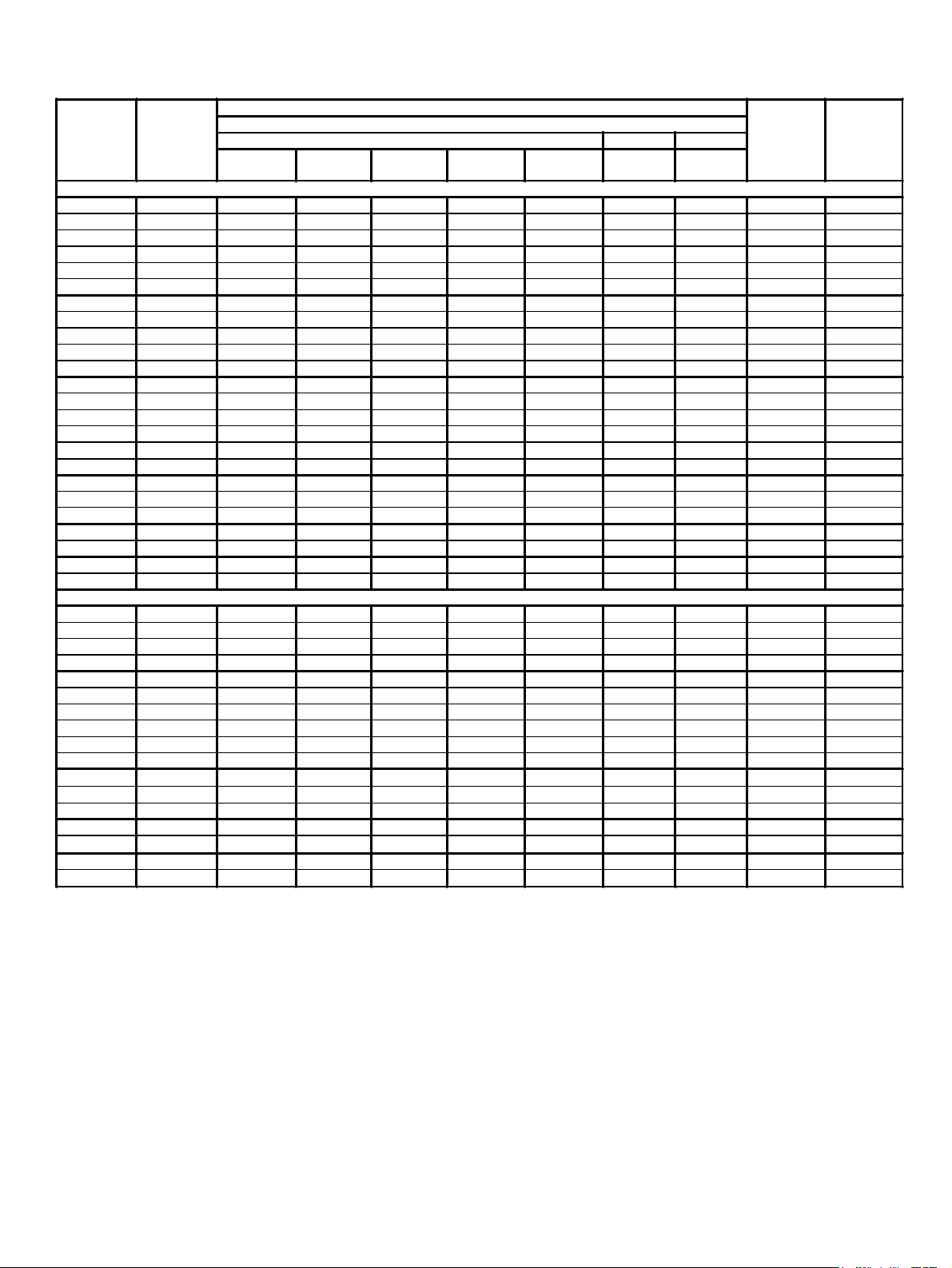
CAPACITY DATA - 850 RPM MODELS - R404A
TOTAL HEAT OF REJECTION CAPACITY (MBH)
BVC
MODEL
NUMBER
007
009
010
011
012
013
017
019
022
024
027
029
034
037
041
043
048
056
063
068
079
085
095
103
039
045
049
054
058
067
073
081
086
096 2 x 3 44.64 446 670 893 1339 43.75 41.07 90 0.50
112
126
137
158
172
190
206
Fan Rows
1°F
(0.56°C)
1 x 1 3.070 30.7 46.1 61.4 92.1 2.825 2.517 7 0.44
1 x 1 4.011 40.1 60.2 80.2 120 3.731 3.410 8 0.50
1 x 1 4.515 45.2 67.7 90.3 135 4.199 3.838 9 0.50
1 x 1 5.204 52.0 78.1 104 156 4.944 4.579 12 0.43
1 x 1 5.699 57.0 85.5 114 171 5.414 5.015 12 0.47
1 x 1 6.271 62.7 94.1 125 188 6.146 5.770 15 0.42
1 x 2 8.017 80.2 120 160 241 7.455 6.814 14 0.57
1 x 2 8.987 89.9 135 180 270 8.358 7.639 18 0.50
1 x 2 10.41 104 156 208 312 9.892 9.164 24 0.43
1 x 2 11.41 114 171 228 342 10.84 10.04 24 0.48
1 x 2 12.55 125 188 251 376 12.30 11.54 30 0.42
1 x 3 13.55 135 203 271 406 12.51 11.51 27 0.50
1 x 3 15.58 156 234 312 467 14.80 13.71 36 0.43
1 x 3 17.11 171 257 342 513 16.25 15.05 36 0.48
1 x 3 18.82 188 282 376 565 18.44 17.31 45 0.42
1 x 3 20.02 200 300 400 601 19.02 17.62 36 0.56
1 x 3 22.32 223 335 446 670 21.87 20.53 45 0.50
1 x 4 25.55 256 383 511 767 23.77 21.72 22 1.16
1 x 4 29.38 294 441 588 881 27.91 25.85 30 0.98
1 x 4 31.58 316 474 632 947 30.94 29.05 37 0.85
1 x 5 36.81 368 552 736 1104 34.97 32.39 30 1.23
1 x 5 39.48 395 592 790 1184 38.69 36.32 37 1.07
1 x 6 44.17 442 663 883 1325 41.96 38.87 30 1.47
1 x 6 47.37 474 711 947 1421 46.41 43.58 37 1.28
2 x 2 18.04 180 271 361 541 16.78 15.34 36 0.50
2 x 2 20.82 208 312 416 625 19.78 18.32 48 0.43
2 x 2 22.80 228 342 456 684 21.66 20.06 48 0.47
2 x 2 25.06 251 376 501 752 24.56 23.05 60 0.42
2 x 3 27.06 271 406 541 812 25.17 23.00 54 0.50
2 x 3 31.20 312 468 624 936 29.64 27.46 72 0.43
2 x 3 34.18 342 513 684 1025 32.47 30.08 72 0.47
2 x 3 37.60 376 564 752 1128 36.85 34.59 90 0.42
2 x 3 40.05 400 601 801 1201 38.04 35.24 72 0.56
2 x 4 52.27 523 784 1045 1568 48.61 44.43 45 1.16
2 x 4 58.75 588 881 1175 1763 55.82 51.70 60 0.98
2 x 4 64.01 640 960 1280 1920 62.73 58.88 75 0.85
2 x 5 73.62 736 1104 1472 2209 69.94 64.78 60 1.23
2 x 5 80.02 800 1200 1600 2401 78.42 73.62 75 1.07
2 x 6 88.34 883 1325 1767 2650 83.93 77.74 60 1.47
2 x 6 96.02 960 1440 1920 2881 94.10 88.34 75 1.28
10°F
(5.56°C)
TEMPERATURE DIFFERENCE (TD)
12 FPI 10 FPI 8 FPI
15°F
(8.3°C)
Single Row Models
Double Row Models
20°F
(11.1°C)
30°F
(16.7°C)
1°F
(0.56°C)
1°F
(0.56°C)
Maximum
No. of
Feeds
MBH
@ 1° F TD
Per Feed
(12 FPI)
To calculate capacities with other refrigerants, multiply the R22 capacity by the appropriate correction factor.
Refer to the table accompanying each of the R22 tables.
NOTES: (1) Above capacity data based on 0°F subcooling and at sea level.
(2) TD = Condensing temperature - ambient temperature
(3) Standard fin spacing is 12 FPI except models 056 and 112 (13 FPI).
(4) For High Altitude applications apply the following correction factors:
0.94 for 2000 feet, 0.88 for 4000 feet and 0.81 for 6000 feet.
(5) For 50Hz capacity multiply by 0.92.
- 3 -
Page 4
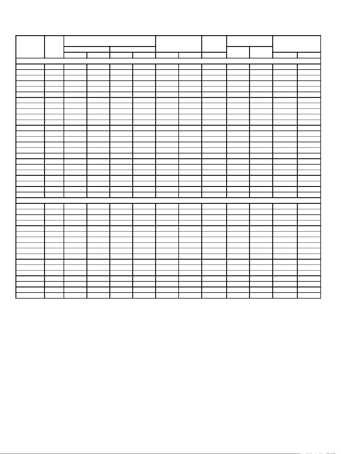
GENERAL SPECIFICATIONS - 850 RPM MODELS
BVC
MODEL
NUMBER
Total
No. of
Feeds
R22 Refrigerant Charge
(2)
Normal
lbs kg lbs kg CFM m3/h dBA lbs kg
(1)
90% FULL
Sound
(3)
Air Flow Rate
(4)
Level
Piping Connections
(5)
Inlet
Qty - OD
Outlet
Qty - OD
Condenser
Weight
(6)
Single Row Models
1A11007 7 1.7 0.8 11.0 5.2 7150 12200 63.5 1 - 1 1/8 1 - 7/8 360 163
1A11009 8 2.2 1.0 17.0 7.5 6280 10700 63.5 1 - 1 3/8 1 - 7/8 375 170
1A11010 9 2.8 1.3 21.0 9.5 7150 12200 63.5 1 - 1 3/8 1 - 7/8 420 191
1A11011 12 3.9 1.8 27.0 12.0 6880 11700 63.5 1 - 1 3/8 1 - 1 1/8 440 200
1A11012 12 4.3 2.0 31.0 14.0 7200 12200 63.5 1 - 1 3/8 1 - 1 1/8 480 218
1A11013 15 5.2 2.4 39.0 18.0 6930 11800 63.5 1 - 1 5/8 1 - 1 1/8 505 229
1A12017 14 4.1 1.9 31.0 14.0 12500 21300 66.5 1 - 1 5/8 1 - 1 1/8 565 256
1A12019 18 6.1 2.8 44.0 20.0 14300 24300 66.5 1 - 2 1/8 1 - 1 3/8 630 286
1A12022 24 7.4 3.4 55.0 25.0 13700 23300 66.5 1 - 2 1/8 1 - 1 3/8 675 306
1A12024 24 8.3 3.8 62.0 28.0 14400 24500 66.5 1 - 2 1/8 1 - 1 3/8 740 336
1A12027 30 10.0 4.5 75.0 34.0 13900 23600 66.5 1 - 2 1/8 1 - 1 3/8 790 358
1A13029 27 9.0 4.1 61.0 28.0 21400 36400 67.7 1 - 2 1/8 1 - 1 5/8 840 381
1A13034 36 10.0 4.5 78.0 35.0 20600 35000 67.7 1 - 2 1/8 1 - 1 5/8 905 410
1A13037 36 12.0 5.4 94.0 42.0 21600 36700 67.7 1 - 2 5/8 1 - 1 5/8 1000 454
1A13041 45 14.0 6.4 113 51.0 20800 35400 67.7 1 - 2 5/8 1 - 1 5/8 1070 485
1A13043 36 17.5 7.9 128 57.8 26500 45100 67.7 1 - 2 5/8 1 - 1 5/8 1055 479
1A13048 45 20.5 9.3 152 68.9 25800 43800 67.7 1 - 2 5/8 1 - 1 5/8 1150 522
2A14056 22 25.9 11.8 183 83.2 35900 61000 69 1 - 2 5/8 1 - 2 1/8 1600 726
2A14063 30 32.5 14.7 239 108 35300 59900 69 1 - 2 5/8 1 - 2 1/8 1650 748
2A14068 37 38.0 17.2 286 130 34300 58300 69 1 - 2 5/8 1 - 2 1/8 1750 794
2A15079 30 38.5 17.5 290 131 44100 74900 70.3 1 - 2 5/8 1 - 2 1/8 2063 936
2A15085 37 48.8 22.2 356 161 42900 72900 70.3 1 - 2 5/8 1 - 2 5/8 2188 992
2A16095 30 53.5 24.3 365 165 52900 89900 71 1 - 3 1/8 1 - 3 1/8 2475 1123
2A16103 37 61.2 27.7 436 198 51500 87500 71 1 - 3 1/8 1 - 3 1/8 2625 1191
Double Row Models
1A22039 36 16.0 7.3 104 47.0 28600 48600 69.5 2 - 2 1/8 2 - 1 3/8 1060 481
1A22045 48 19.0 8.6 126 57.0 27500 46800 69.5 2 - 2 1/8 2 - 1 3/8 1145 519
1A22049 48 21.0 9.5 141 64.0 28800 49000 69.5 2 - 2 1/8 2 - 1 3/8 1255 569
1A22054 60 23.0 10.0 167 76.0 27700 47100 69.5 2 - 2 1/8 2 - 1 3/8 1350 612
1A23058 54 22.0 10.0 141 64.0 42800 72800 71 2 - 2 1/8 2 - 1 5/8 1420 644
1A23067 72 26.0 12.0 174 79.0 41200 70000 71 2 - 2 1/8 2 - 1 5/8 1550 703
1A23073 72 30.0 14.0 212 96.0 43200 73400 71 2 - 2 5/8 2 - 1 5/8 1710 776
1A23081 90 35.0 16.0 251 114 41600 70700 71 2 - 2 5/8 2 - 1 5/8 1865 846
1A23086 72 35.0 16.0 255 116 53000 90100 71 2 - 2 5/8 2 - 1 5/8 2110 957
1A23096 90 41.0 19.0 304 138 51500 87600 71 2 - 2 5/8 2 - 1 5/8 2300 1043
2A24112 45 53.0 24.0 375 170 71800 122100 72.5 2 - 2 5/8 2 - 2 1/8 3200 1451
2A24126 60 65.0 30.0 477 217 70500 119900 72.5 2 - 2 5/8 2 - 2 1/8 3300 1497
2A24137 75 77.0 35.0 579 263 68600 116600 72.5 2 - 2 5/8 2 - 2 1/8 3500 1588
2A25158 60 77.0 35.0 579 263 88100 149800 73.3 2 - 2 5/8 2 - 2 1/8 4125 1871
2A25172 75 99.0 45.0 721 327 85800 145800 73.3 2 - 2 5/8 2 - 2 5/8 4375 1984
2A26190 60 107.0 49.0 729 331 106000 179800 74 2 - 3 1/8 2 - 3 1/8 4950 2245
2A26206 75 124.0 56.0 883 401 102900 174900 74 2 - 3 1/8 2 - 3 1/8 5250 2381
(1) For R407A, R507 use R22 Charge x 0.87. For R407-C use R22 Charge x 0.97.
For R134a and R502 use R22 Charge. For R12 use R22 Charge X 1.1.
(2) Normal Charge is the refrigerant charge for warm ambient or summer operation. For low ambient or winter charge with
flooded head pressure control and fan cycling see Page 33 and Page 34.
(3) 90% FULL is the liquid refrigerant weight at 90% of internal volume and is for reference ONLY.
(4) For 50Hz Fan Data use 60Hz CFM (m3/h) X 0.83.
(5) Sound Pressure Level at ten meter distance.
(6) Less weight of refrigerant charge.
- 4 -
Page 5
ELECTRICAL DATA - 850 RPM MODELS 60Hz
Not available on 4 and 5 fan single row models
Not available on 4 and 5 fan single row models
NO.
OF
FANS
1 3.4 4.3 15 5.9 7.4 15 2.9 3.6 15 2.3 2.9 15
2 6.8 7.7 15 11.8 13.3 20 5.8 6.5 15 4.6 5.2 15
3 10.2 11.1 15 17.7 19.2 25 8.7 9.4 15 6.9 7.5 15
4 13.6 14.5 20 23.6 25.1 30 11.6 12.3 15 9.2 9.8 15
5 N/A N/A N/A 29.5 35.1 40 14.5 15.2 20 11.5 12.1 15
6 20.4 21.3 30 35.4 36.9 45 17.4 18.1 25 13.8 14.4 20
8 NA NA NA 47.2 48.7 60 23.2 23.9 30 18.4 19.0 25
10 NA NA NA 59 60.5 70 29 29.7 40 23 23.6 30
12 NA NA NA 70.8 72.3 80 34.8 35.5 45 27.6 28.2 40
M.C.A. = Minimum Circuit Ampacity (AMPS)
M.O.P. = Maximum Overcurrent Protection (AMPS)
208-230/1/60* 208-230/3/60 460/3/60 575/3/60
TOTAL
FLA
MCA MOP
TOTAL
FLA
MCA MOP
TOTAL
FLA
MCA MOP
TOTAL
*
and 6 fan models 183” and longer.
FLA
MCA MOP
ELECTRICAL DATA - 850 (700) RPM MODELS 50Hz
NO.
OF
FANS
1 3.6 4.5 15 6.5 8.1 15 2.7 3.4 15
2 7.2 8.1 15 13 14.6 20 5.4 6.1 15
3 10.8 11.7 15 19.5 21.1 25 8.1 8.8 15
4 14.4 15.3 20 26 27.6 40 10.8 11.5 15
5 N/A N/A N/A 32.5 34.1 40 13.5 15.1 20
6 21.6 22.5 30 39 40.6 45 16.2 16.9 20
8 NA NA NA 52 53.6 60 21.6 22.3 30
10 NA NA NA 65 66.6 80 27 27.7 40
12 NA NA NA 78 79.6 90 32.4 33.1 45
TOTAL
FLA
M.C.A. = Minimum Circuit Ampacity (AMPS)
M.O.P. = Maximum Overcurrent Protection (AMPS)
200-220/1/50 200-220/3/50* 380-400/3/50
MCA MOP
TOTAL
FLA
MCA MOP TOTAL FLA MCA MOP
*
and 6 fan models 183” and longer.
- 5 -
Page 6
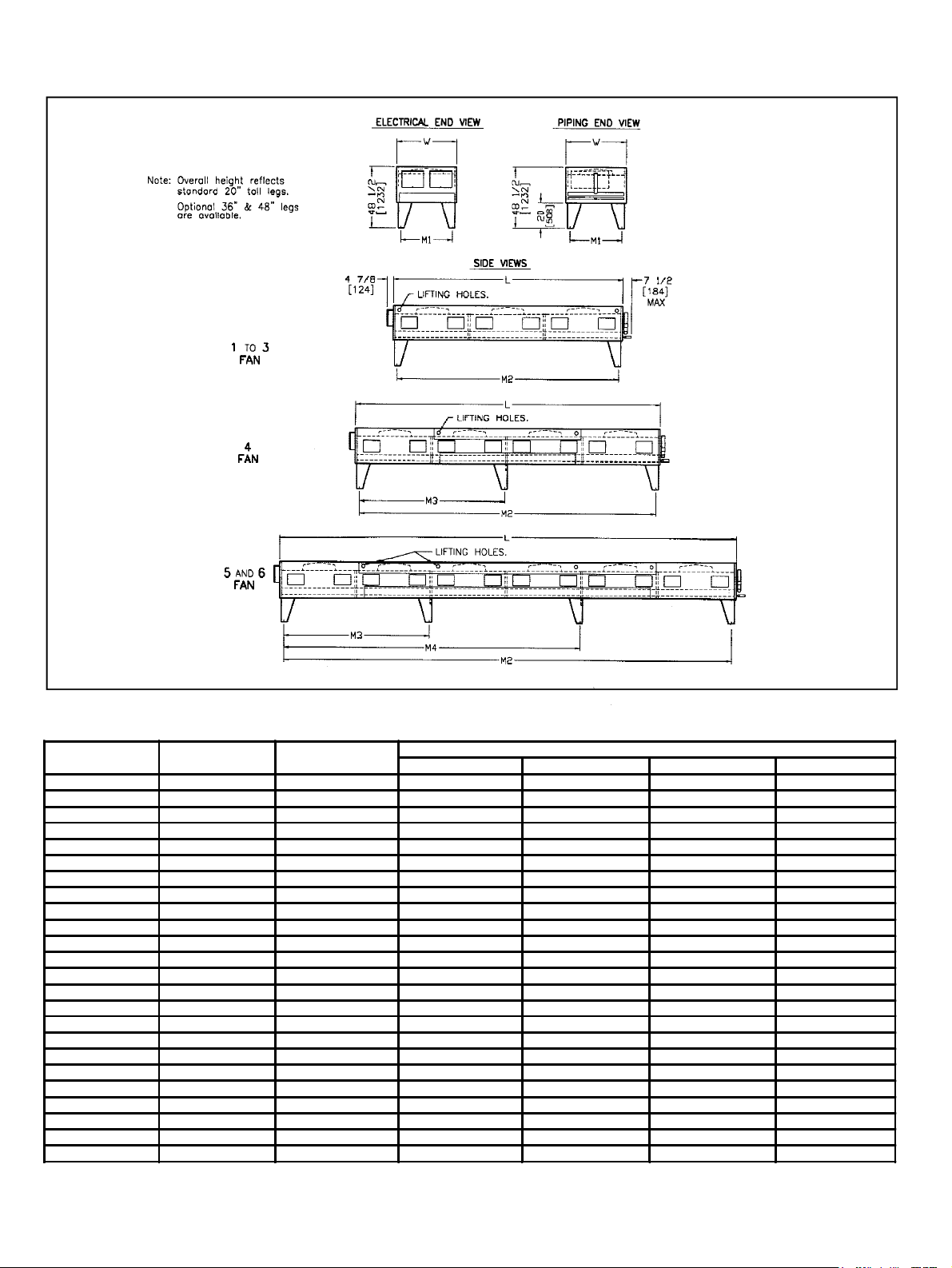
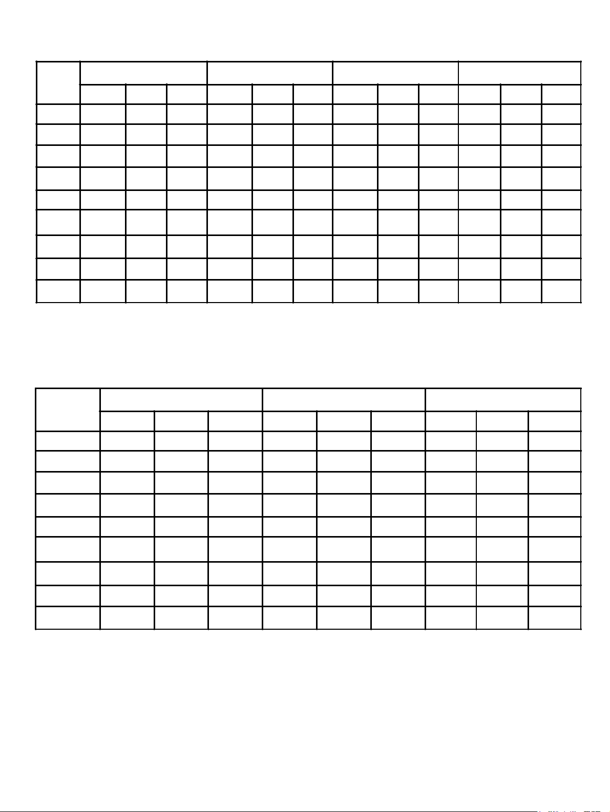
DIMENSIONAL DATA - SINGLE ROW BVC MODELS
DIMENSIONS - Inches (mm)
SINGLE ROW
MODEL
11 007
11 009
11 010 48 1/8 (1222) 43 (1092) 41 1/8 (1045) 36 (914) - -
11 011
11 012
11 013 48 1/8 (1222) 50 (127) 41 1/8 (1045) 43 (1092) - 12 017
12 019
12 022
12 024
12 027 48 1/8 (1222) 97 1/8 (2467) 41 1/8 (1045) 90 1/8 (2289) - 13 029
13 034
13 037
13 041 48 1/8 (1222) 144 1/4 (3664) 41 1/8 (1045) 137 1/4 (3486) - 13 043
13 048
14 056 48 1/8 (1222) 243 (6172) 41 1/8 (1045) 236 5/16 ( 6002) 116 3/16 (2951) 14 063
14 068
15 079
15 085 48 1/8 (1222) 303 (7696) 41 1/8 (1045) 296 5/16 (7526) 116 3/16 (2951) 176 3/16 (4475)
16 095
16 103
WIDTH
W
38 1/8 (968) 43 (1092) 31 1/8 (791) 36 (914) - 38 1/8 (968) 43 (1092) 31 1/8 (791) 36 (914) - -
48 1/8 (1222) 43 (1092) 41 1/8 (1045) 36 (914) - 48 1/8 (1222) 50 (127) 41 1/8 (1045) 43 (1092) - -
38 1/8 (968) 83 1/8 (2111) 31 1/8 (791) 76 1/8 (1934) - 48 1/8 (1222) 83 1/8 (2111) 41 1/8 (1045) 76 1/8 (1934) - 48 1/8 (1222) 83 1/8 (2111) 41 1/8 (1045) 76 1/8 (1934) - 48 1/8 (1222) 97 1/8 (2467) 41 1/8 (1045) 90 1/8 (2289) - -
48 1/8 (1222) 123 1/4 (3131) 41 1/8 (1045) 116 1/4 (2953) - 48 1/8 (1222) 123 1/4 (3131) 41 1/8 (1045) 116 1/4 (2953) - 48 1/8 (1222) 144 1/4 (3664) 41 1/8 (1045) 137 1/4 (3486) - -
48 1/8 (1222) 183 (4648) 41 1/8 (1045) 176 1/4 (4477) - 48 1/8 (1222) 183 (4648) 41 1/8 (1045) 176 1/4 (4477) - -
48 1/8 (1222) 243 (6172) 41 1/8 (1045) 236 5/16 ( 6002) 116 3/16 (2951) 48 1/8 (1222) 243 (6172) 41 1/8 (1045) 236 5/16 ( 6002) 116 3/16 (2951) 48 1/8 (1222) 303 (7696) 41 1/8 (1045) 296 5/16 (7526) 116 3/16 (2951) 176 3/16 (4475)
48 1/8 (1222) 363 (9220) 41 1/8 (1045) 356 5/16 (9050) 116 3/16 (2951) 236 3/16 ( 5999)
48 1/8 (1222) 363 (9220) 41 1/8 (1045) 356 5/16 (9050) 116 3/16 (2951) 236 3/16 ( 5999)
LENGTH
L
M1 M2 M3 M4
MOUNTING LEG CENTRES
- 6 -
Page 7
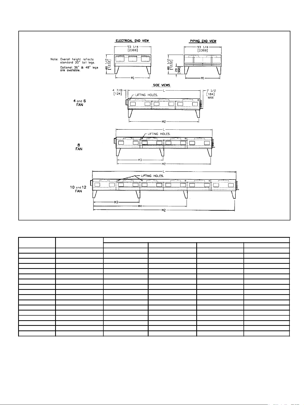
DIMENSIONAL DATA - DOUBLE ROW BVC MODELS
DIMENSIONS - Inches (mm)
DOUBLE ROW
MODEL
22 039
22 045
22 049 97 1/8 (2467) 86 1/8 (2188) 90 1/8 (2289) - 22 054
23 058
23 067
23 073
23 081
23 086
23 096
24 112 243 (6172) 86 7/16 (2196) 236 5/16 ( 6002) 116 3/16 (2951) 24 126
24 137
25 158
25 172 303 (7696) 86 7/16 (2196) 296 5/16 (7526) 116 3/16 (2951) 176 3/16 (4475)
26 190
26 206
LENGTH
L
83 1/8 (2111) 86 1/8 (2188) 76 1/8 (1934) - 83 1/8 (2111) 86 1/8 (2188) 76 1/8 (1934) - -
97 1/8 (2467) 86 1/8 (2188) 90 1/8 (2289) - 123 1/4 (3131) 86 1/8 (2188) 116 1/4 (2953) - 123 1/4 (3131) 86 1/8 (2188) 116 1/4 (2953) - 144 1/4 (3664) 86 1/8 (2188) 137 1/4 (3486) - 144 1/4 (3664) 86 1/8 (2188) 137 1/4 (3486) - -
183 (4648) 86 7/16 (2196) 176 1/4 (4477) - 183 (4648) 86 7/16 (2196) 176 1/4 (4477) - -
243 (6172) 86 7/16 (2196) 236 5/16 ( 6002) 116 3/16 (2951) 243 (6172) 86 7/16 (2196) 236 5/16 ( 6002) 116 3/16 (2951) 303 (7696) 86 7/16 (2196) 296 5/16 (7526) 116 3/16 (2951) 176 3/16 (4475)
363 (9220) 86 7/16 (2196) 356 5/16 (9050) 116 3/16 (2951) 236 3/16 ( 5999)
363 (9220) 86 7/16 (2196) 356 5/16 (9050) 116 3/16 (2951) 236 3/16 ( 5999)
M1 M2 M3 M4
MOUNTING LEG CENTRES
- 7 -
Page 8
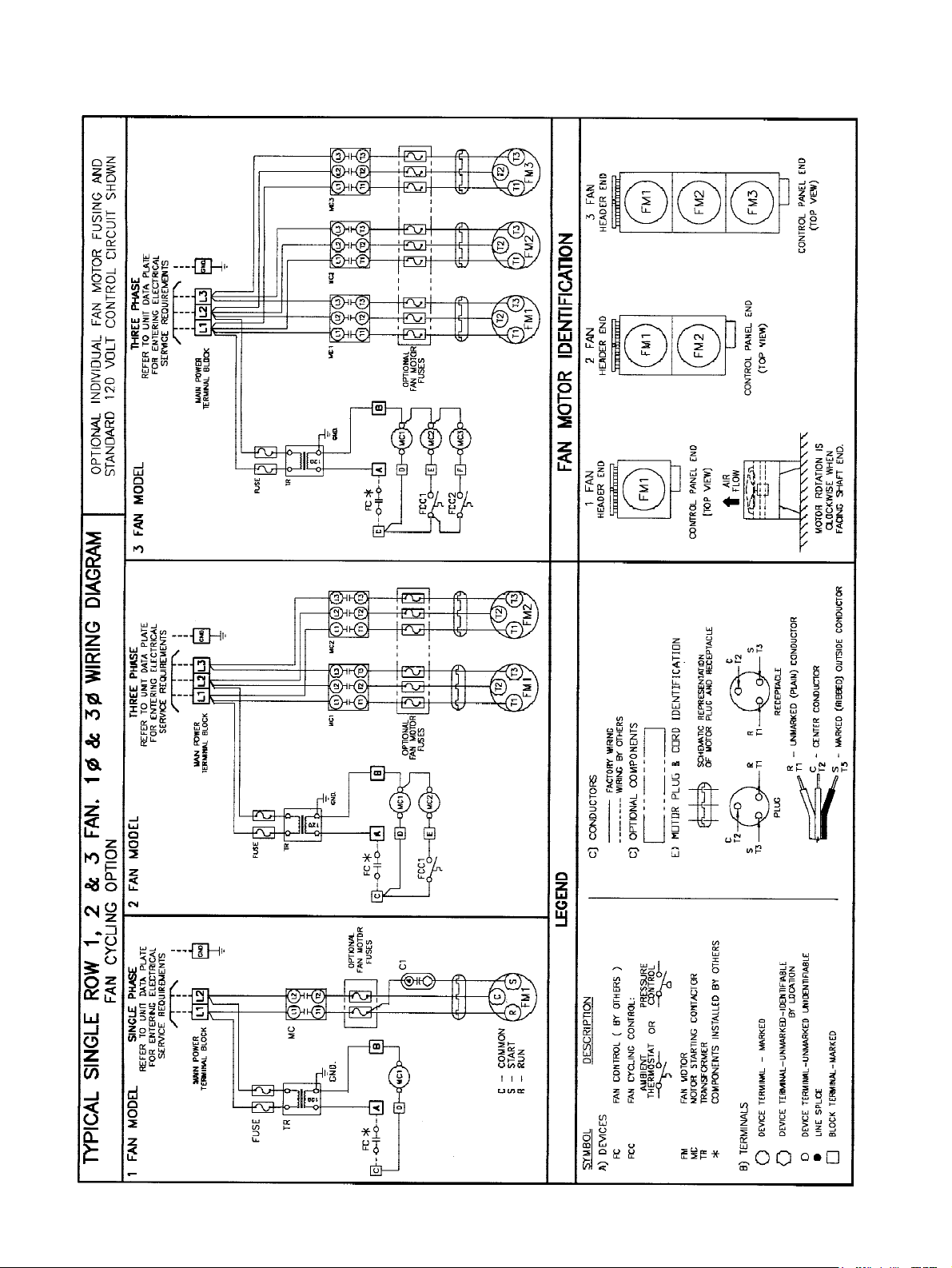
WIRING DIAGRAMS
(SINGLE ROW MODELS)
Note: 1∅ Motors not available
on 183” long models.
- 8 -
Page 9
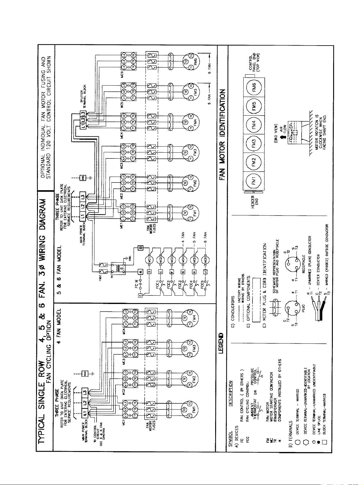
WIRING DIAGRAMS
(SINGLE ROW MODELS)
- 9 -
Page 10
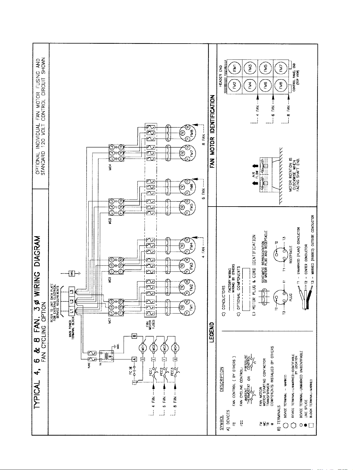
WIRING DIAGRAMS
(DOUBLE ROW MODELS)
- 10 -
Page 11

WIRING DIAGRAMS
(DOUBLE ROW MODELS)
- 11 -
Page 12
CAPACITY DATA - 550 RPM MODELS - R22
BVC
MODEL
NUMBER
007
009
010
011
012
013
017
019
022
024
027
029
034
037
041
043
048
056
063
068
079
085
095
103
039
045
049
054
058
067
073
081
086
096
112
126
137
158
172
190
206
TOTAL HEAT OF REJECTION CAPACITY (MBH)
Fan Rows
1°F
(0.56°C)
1 x 1 2.540 25.4 38.1 50.8 76.2 2.324 2.059 4 0.63
1 x 1 3.162 31.6 47.4 63.2 94.8 3.011 2.760 8 0.40
1 x 1 3.523 35.2 52.8 70.5 106 3.312 3.014 9 0.39
1 x 1 3.949 39.5 59.2 79.0 118 3.822 3.568 8 0.49
1 x 1 4.298 43.0 64.5 86.0 129 4.104 3.835 8 0.54
1 x 1 4.580 45.8 68.7 91.6 137 4.503 4.288 10 0.46
1 x 2 6.316 63.2 94.7 126 189 6.015 5.514 14 0.45
1 x 2 7.008 70.1 105 140 210 6.589 5.997 18 0.39
1 x 2 7.898 79.0 118 158 237 7.644 7.136 18 0.44
1 x 2 8.603 86.0 129 172 258 8.215 7.677 18 0.48
1 x 2 9.159 91.6 137 183 275 9.006 8.575 18 0.51
1 x 3 10.56 106 158 211 317 9.930 9.037 18 0.59
1 x 3 11.82 118 177 236 355 11.44 10.68 24 0.49
1 x 3 12.89 129 193 258 387 12.31 11.51 24 0.54
1 x 3 13.73 137 206 275 412 13.50 12.86 30 0.46
1 x 3 15.24 152 229 305 457 14.17 13.32 36 0.42
1 x 3 16.20 162 243 324 486 15.59 14.92 45 0.36
1 x 4 20.23 202 303 405 607 19.02 17.32 15 1.35
1 x 4 22.53 225 338 451 676 21.52 20.10 20 1.13
1 x 4 23.66 237 355 473 710 23.26 22.15 25 0.95
1 x 5 28.24 282 424 565 847 26.97 25.19 30 0.94
1 x 5 29.18 292 438 592 887 28.69 27.32 37 0.79
1 x 6 33.88 339 508 678 1017 32.36 30.23 30 1.13
1 x 6 35.02 350 525 710 1065 34.42 32.78 37 0.95
2 x 2 14.06 141 211 281 422 13.22 12.03 27 0.52
2 x 2 15.79 158 237 316 474 15.28 14.27 36 0.44
2 x 2 17.18 172 258 344 515 16.40 15.33 36 0.48
2 x 2 18.29 183 274 366 549 17.98 17.12 45 0.41
2 x 3 21.09 211 316 422 633 19.83 18.05 36 0.59
2 x 3 23.66 237 355 473 710 22.90 21.37 48 0.49
2 x 3 25.76 258 386 515 773 24.60 22.99 48 0.54
2 x 3 27.44 274 412 549 823 26.98 25.69 60 0.46
2 x 3 30.48 305 457 610 914 28.34 26.63 72 0.42
2 x 3 32.39 324 486 648 972 31.18 29.85 90 0.36
2 x 4 40.46 405 607 809 1214 38.03 34.63 30 1.35
2 x 4 45.07 451 676 901 1352 43.04 40.20 40 1.13
2 x 4 47.32 473 710 946 1420 46.52 44.29 50 0.95
2 x 5 56.47 565 847 1129 1694 53.93 50.38 60 0.94
2 x 5 59.16 592 887 1183 1775 58.15 55.37 75 0.79
2 x 6 67.77 678 1017 1355 2033 64.72 60.45 60 1.13
2 x 6 70.98 710 1065 1420 2129 69.78 66.44 75 0.95
10°F
(5.56°C)
TEMPERATURE DIFFERENCE (TD)
12 FPI 10 FPI 8 FPI
15°F
(8.3°C)
Double Row Models
20°F
(11.1°C)
Single Row Models
30°F
(16.7°C)
1°F
(0.56°C)
1°F
(0.56°C)
Maximum
No. of
Feeds
MBH
@ 1° F TD
Per Feed
(12 FPI)
Correction Factors for Other refrigerants - Use R22 Values Multiplied By
R134a R12 R507 R404A R407A R407B R502 R407C
0.94 0.95 0.97 0.97 0.97 0.97 0.98 1.00
NOTES: (1) Above capacity data based on 0°F subcooling and at sea level.
(2) TD = Condensing temperature - ambient temperature
(3) Standard fin spacing is 12 FPI except models 056 and 112 (13 FPI).
(4) For High Altitude applications apply the following correction factors:
0.94 for 2000 feet, 0.88 for 4000 feet and 0.81 for 6000 feet.
(5) For 50Hz capacity multiply by 0.92.
- 12 -
Page 13

CAPACITY DATA - 550 RPM MODELS - R404A
BVC
MODEL
NUMBER
007
009
010
011
012
013
017
019
022
024
027
029
034
037
041
043
048
056
063
068
079
085
095
103
039
045
049
054
058
067
073
081
086
096
112
126
137
158
172
190
206
TOTAL HEAT OF REJECTION CAPACITY (MBH)
Fan Rows
1°F
(0.56°C)
1 x 1 2.464 24.6 37.0 49.3 73.9 2.254 1.998 4 0.62
1 x 1 3.067 30.7 46.0 61.3 92.0 2.921 2.677 8 0.38
1 x 1 3.417 34.2 51.3 68.3 103 3.213 2.924 9 0.38
1 x 1 3.830 38.3 57.5 76.6 115 3.707 3.461 8 0.48
1 x 1 4.169 41.7 62.5 83.4 125 3.981 3.720 8 0.52
1 x 1 4.442 44.4 66.6 88.8 133 4.368 4.159 10 0.44
1 x 2 6.126 61.3 91.9 123 184 5.834 5.348 14 0.44
1 x 2 6.798 68.0 102 136 204 6.391 5.817 18 0.38
1 x 2 7.661 76.6 115 153 230 7.415 6.922 18 0.43
1 x 2 8.345 83.5 125 167 250 7.969 7.447 18 0.46
1 x 2 8.885 88.8 133 178 267 8.736 8.318 18 0.49
1 x 3 10.24 102 154 205 307 9.632 8.766 18 0.57
1 x 3 11.46 115 172 229 344 11.09 10.36 24 0.48
1 x 3 12.51 125 188 250 375 11.94 11.16 24 0.52
1 x 3 13.32 133 200 266 400 13.10 12.47 30 0.44
1 x 3 14.78 148 222 296 443 13.75 12.92 36 0.41
1 x 3 15.71 157 236 314 471 15.12 14.48 45 0.35
1 x 4 19.19 192 288 392 589 18.44 16.80 15 1.28
1 x 4 21.86 219 328 437 656 20.87 19.50 20 1.09
1 x 4 22.64 226 340 459 689 22.56 21.48 25 0.91
1 x 5 27.39 274 411 548 822 26.16 24.43 30 0.91
1 x 5 28.31 283 425 574 861 27.82 26.50 37 0.77
1 x 6 32.87 329 493 657 986 31.39 29.32 30 1.10
1 x 6 33.97 340 510 689 1033 33.39 31.80 37 0.92
2 x 2 13.64 136 205 273 409 12.82 11.67 27 0.51
2 x 2 15.31 153 230 306 459 14.82 13.84 36 0.43
2 x 2 16.66 167 250 333 500 15.91 14.87 36 0.46
2 x 2 17.74 177 266 355 532 17.44 16.61 45 0.39
2 x 3 20.46 205 307 409 614 19.24 17.51 36 0.57
2 x 3 22.95 229 344 459 688 22.21 20.73 48 0.48
2 x 3 24.99 250 375 500 750 23.86 22.30 48 0.52
2 x 3 26.62 266 399 532 799 26.17 24.92 60 0.44
2 x 3 29.57 296 443 591 887 27.49 25.83 72 0.41
2 x 3 31.42 314 471 628 943 30.24 28.95 90 0.35
2 x 4 39.24 392 589 785 1177 36.89 33.59 30 1.31
2 x 4 43.72 437 656 874 1311 41.75 38.99 40 1.09
2 x 4 45.90 459 689 918 1377 45.12 42.96 50 0.92
2 x 5 54.78 548 822 1096 1643 52.32 48.86 60 0.91
2 x 5 57.38 574 861 1148 1722 56.41 53.71 75 0.77
2 x 6 65.74 657 986 1315 1972 62.78 58.64 60 1.10
2 x 6 68.85 689 1033 1377 2066 67.68 64.45 75 0.92
10°F
(5.56°C)
TEMPERATURE DIFFERENCE (TD)
12 FPI 10 FPI 8 FPI
15°F
(8.3°C)
20°F
(11.1°C)
Single Row Models
Double Row Models
30°F
(16.7°C)
1°F
(0.56°C)
1°F
(0.56°C)
Maximum
No. of
Feeds
MBH
@ 1° F TD
Per Feed
(12 FPI)
To calculate capacities with other refrigerants, multiply the R22 capacity by the appropriate correction factor.
Refer to the table accompanying each of the R22 tables.
NOTES: (1) Above capacity data based on 0°F subcooling and at sea level.
(2) TD = Condensing temperature - ambient temperature
(3) Standard fin spacing is 12 FPI except models 056 and 112 (13 FPI).
(4) For High Altitude applications apply the following correction factors:
0.94 for 2000 feet, 0.88 for 4000 feet and 0.81 for 6000 feet.
(5) For 50Hz capacity multiply by 0.92.
- 13 -
Page 14

GENERAL SPECIFICATIONS - 550 RPM MODELS - R22
BVC
MODEL
NUMBER
1B11007 4 1.7 0.8 11.0 5.2 4630 7900 1 - 1 1/8 1 - 7/8 360 163
1B11009 8 2.2 1.0 17.0 7.5 4060 6900 1 - 1 3/8 1 - 7/8 375 170
1B11010 9 2.8 1.3 21.0 9.5 4630 7900 1 - 1 3/8 1 - 7/8 420 191
1B11011 8 3.9 1.8 27.0 12.0 4450 7600 1 - 1 3/8 1 - 1 1/8 440 200
1B11012 8 4.3 2.0 31.0 14.0 4660 7900 1 - 1 3/8 1 - 1 1/8 480 218
1B11013 10 5.2 2.4 39.0 18.0 4480 7600 1 - 1 5/8 1 - 1 1/8 505 229
1B12017 14 4.1 1.9 31.0 14.0 8100 13800 1 - 1 5/8 1 - 1 1/8 565 256
1B12019 18 6.1 2.8 44.0 20.0 9300 15700 1 - 2 1/8 1 - 1 3/8 630 286
1B12022 18 7.4 3.4 55.0 25.0 8900 15100 1 - 2 1/8 1 - 1 3/8 675 306
1B12024 18 8.3 3.8 62.0 28.0 9300 15800 1 - 2 1/8 1 - 1 3/8 740 336
1B12027 18 10.0 4.5 75.0 34.0 9000 15300 1 - 2 1/8 1 - 1 3/8 790 358
1B13029 18 9.0 4.1 61.0 28.0 13800 23500 1 - 2 1/8 1 - 1 5/8 840 381
1B13034 24 10.0 4.5 78.0 35.0 13300 22700 1 - 2 1/8 1 - 1 5/8 905 410
1B13037 24 12.0 5.4 94.0 42.0 14000 23800 1 - 2 5/8 1 - 1 5/8 1000 454
1B13041 30 14.0 6.4 113 51.0 13500 22900 1 - 2 5/8 1 - 1 5/8 1070 485
1B13043 36 17.5 7.9 128 57.8 17100 29200 1 - 2 5/8 1 - 1 5/8 1055 479
1B13048 45 20.5 9.3 152 68.9 16700 28300 1 - 2 5/8 1 - 1 5/8 1150 522
2B14056 15 25.9 11.8 183 83.2 23200 39500 1 - 2 5/8 1 - 2 1/8 1600 726
2B14063 20 32.5 14.7 239 108 22800 38800 1 - 2 5/8 1 - 2 1/8 1650 748
2B14068 25 38.0 17.2 286 130 22200 37700 1 - 2 5/8 1 - 2 1/8 1750 794
2B15079 30 38.5 17.5 290 131 28500 48500 1 - 2 5/8 1 - 2 1/8 2063 936
2B15085 37 48.8 22.2 356 161 27700 47200 1 - 2 5/8 1 - 2 5/8 2188 992
2B16095 30 53.5 24.3 365 165 34200 58200 1 - 3 1/8 1 - 3 1/8 2475 1123
2B16103 37 61.2 27.7 436 198 33300 56600 1 - 3 1/8 1 - 3 1/8 2625 1191
1B22039 27 16.0 7.3 104 47.0 18500 31500 2 - 2 1/8 2 - 1 3/8 1060 481
1B22045 36 19.0 8.6 126 57.0 17800 30300 2 - 2 1/8 2 - 1 3/8 1145 519
1B22049 36 21.0 9.5 141 64.0 18600 31700 2 - 2 1/8 2 - 1 3/8 1255 569
1B22054 45 23.0 10.0 167 76.0 17900 30500 2 - 2 1/8 2 - 1 3/8 1350 612
1B23058 36 22.0 10.0 141 64.0 27700 47100 2 - 2 1/8 2 - 1 5/8 1420 644
1B23067 48 26.0 12.0 174 79.0 26700 45300 2 - 2 1/8 2 - 1 5/8 1550 703
1B23073 48 30.0 14.0 212 96.0 28000 47500 2 - 2 5/8 2 - 1 5/8 1710 776
1B23081 60 35.0 16.0 251 114 26900 45800 2 - 2 5/8 2 - 1 5/8 1865 846
1B23086 72 35.0 16.0 255 116 34300 58300 2 - 2 5/8 2 - 1 5/8 2110 957
1B23096 90 41.0 19.0 304 138 33300 56700 2 - 2 5/8 2 - 1 5/8 2300 1043
2B24112 30 53.0 24.0 375 170 46500 79000 2 - 2 5/8 2 - 2 1/8 3200 1451
2B24126 40 65.0 30.0 477 217 45600 77600 2 - 2 5/8 2 - 2 1/8 3300 1497
2B24137 50 77.0 35.0 579 263 44400 75500 2 - 2 5/8 2 - 2 1/8 3500 1588
2B25158 60 77.0 35.0 579 263 57000 96900 2 - 2 5/8 2 - 2 1/8 4125 1871
2B25172 75 99.0 45.0 721 327 55500 94300 2 - 2 5/8 2 - 2 5/8 4375 1984
2B26190 60 107.0 49.0 729 331 68400 116300 2 - 3 1/8 2 - 3 1/8 4950 2245
2B26206 75 124.0 56.0 883 401 66600 113200 2 - 3 1/8 2 - 3 1/8 5250 2381
Total No.
of Feeds
R22 Refrigerant Charge
(2)
Normal
lbs kg lbs kg CFM m3/h lbs kg
(1)
90% FULL
(3)
Single Row Models
Double Row Models
Air Flow Rate
Piping Connections
(4)
Inlet
Qty - OD
Outlet
Condenser Weight
Qty - OD
(5)
NOTES: (1) For R407A, R507 use R22 Charge x 0.87. For R407-C use R22 Charge x 0.97.
For R134a and R502 use R22 Charge. For R12 use R22 Charge x 1.1.
(2) Normal Charge is the refrigerant charge for warm ambient or summer operation. For low ambient
or winter charge with flooded head pressure control and fan cycling see Page 33 and Page 34.
(3) 90% FULL is the liquid refrigerant weight at 90% of internal volume and is for reference ONLY.
(4) For 50Hz Fan data use 60Hz CFM (m3/h) x 0.83.capacity multiply by 0.92.
(5) Less weight pf refrigerant charge.
- 14 -
Page 15

ELECTRICAL DATA - 550 RPM MODELS 60Hz
NO.
OF
FANS
1
2
3
4
5
6
8
10
12
TOTAL
FLA
208-230/3/60 460/3/60 575/3/60
MCA MOP
2.8 3.5 15 1.3 1.6 15 1.1 1.4 15
5.6 6.3 15 2.6 2.9 15 2.2 2.5 15
8.4 9.1 15 3.9 4.2 15 3.3 3.6 15
11.2 11.9 15 5.2 5.5 15 4.4 4.7 15
14.0 16 20 6.5 6.8 15 5.5 5.8 15
16.8 21 25 7.8 8.1 15 6.6 6.9 15
22.4 26 30 10.4 10.7 15 8.8 9.1 15
28.0 31 35 13 16 20 11 11.3 15
33.6 41 45 15.6 15.9 20 13.2 16 20
M.C.A. = Minimum Circuit Ampacity (AMPS)
M.O.P. = Maximum Overcurrent Protection (AMPS)
ELECTRICAL DATA - 550 (450) RPM MODELS 50Hz
NO.
OF
FANS
1
2
3
4
5
6
8
10
12
TOTAL
FLA
2.2 2.7 15 1 1.2 15
4.4 4.9 15 2 2.2 15
6.5 7.1 15 2.9 3.2 15
8.7 9.3 15 3.9 4.2 15
10.9 11.4 15 4.9 5.1 15
13.1 16 20 5.9 6.1 15
17.4 21 25 7.8 8.1 15
17.4 21 25 7.8 8.1 15
26.2 31 35 11.8 12 15
200-220/3/50 380-400/3/50
MCA MOP
TOTAL
FLA
MCA MOP
TOTAL
FLA
TOTAL
FLA
MCA MOP
MCA MOP
M.C.A. = Minimum Circuit Ampacity (AMPS)
M.O.P. = Maximum Overcurrent Protection (AMPS)
- 15 -
Page 16

CAPACITY DATA - 1140 RPM MODELS - R22
BVC
MODEL
NUMBER
007
009
010
011
012
013
017
019
022
024
027
029
034
037
041
043
048
056
063
068
079
085
095
103
039
045
049
054
058
067
073
081
086
096
112
126
137
158
172
190
206
TOTAL HEAT OF REJECTION CAPACITY (MBH)
Fan Rows
1°F
(0.56°C)
1 x 1 3.627 36.3 54.4 72.5 109 3.303 2.911 7 0.52
1 x 1 4.989 49.9 74.8 100 150 4.677 4.220 8 0.62
1 x 1 5.516 55.2 82.7 110 165 5.094 4.572 9 0.61
1 x 1 6.446 64.5 96.7 129 193 6.118 5.589 12 0.54
1 x 1 7.157 71.6 107 143 215 6.710 6.114 12 0.60
1 x 1 7.985 79.9 120 160 240 7.678 7.095 15 0.53
1 x 2 9.971 100 150 199 299 9.348 8.434 14 0.71
1 x 2 10.98 110 165 220 329 10.14 9.100 18 0.61
1 x 2 12.90 129 194 258 387 12.25 11.19 24 0.54
1 x 2 14.34 143 215 287 430 13.44 12.25 24 0.60
1 x 2 15.98 160 240 320 479 15.37 14.20 30 0.53
1 x 3 16.55 166 248 331 497 15.29 13.72 27 0.61
1 x 3 19.31 193 290 386 579 18.33 16.74 36 0.54
1 x 3 21.49 215 322 430 645 20.15 18.36 36 0.60
1 x 3 23.96 240 359 479 719 23.04 21.29 45 0.53
1 x 3 25.40 254 381 508 762 24.03 21.94 36 0.71
1 x 3 28.48 285 427 570 854 27.14 25.19 45 0.63
1 x 4 31.01 310 465 620 930 28.64 25.71 22 1.41
1 x 4 36.76 368 551 735 1103 34.77 31.76 30 1.23
1 x 4 40.34 403 605 807 1210 38.44 35.67 37 1.09
1 x 5 46.06 461 691 921 1382 43.57 39.79 30 1.54
1 x 5 50.43 504 756 1009 1513 48.06 44.59 37 1.36
1 x 6 55.27 553 829 1105 1658 52.29 47.75 30 1.84
1 x 6 60.51 605 908 1210 1815 57.66 53.51 37 1.64
2 x 2 22.04 220 331 441 661 20.35 18.27 36 0.61
2 x 2 25.79 258 387 516 774 24.48 22.37 48 0.54
2 x 2 28.63 286 429 573 859 26.84 24.45 48 0.60
2 x 2 31.92 319 479 638 957 30.69 28.36 60 0.53
2 x 3 33.06 331 496 661 992 30.53 27.40 54 0.61
2 x 3 38.65 386 580 773 1159 36.69 33.52 72 0.54
2 x 3 42.93 429 644 859 1288 40.25 36.67 72 0.60
2 x 3 47.89 479 718 958 1437 46.05 42.55 90 0.53
2 x 3 50.80 508 762 1016 1524 48.06 43.89 72 0.71
2 x 3 56.97 570 854 1139 1709 54.29 50.38 90 0.63
2 x 4 63.44 634 952 1269 1903 58.58 52.58 45 1.41
2 x 4 73.52 735 1103 1470 2205 69.55 63.51 60 1.23
2 x 4 81.76 818 1226 1635 2453 77.92 72.30 75 1.09
2 x 5 92.12 921 1382 1842 2764 87.15 79.59 60 1.54
2 x 5 102.2 1022 1533 2044 3067 97.41 90.39 75 1.36
2 x 6 110.5 1105 1658 2211 3316 104.6 95.50 60 1.84
2 x 6 122.7 1227 1840 2453 3680 116.9 108.5 75 1.64
10°F
(5.56°C)
TEMPERATURE DIFFERENCE (TD)
12 FPI 10 FPI 8 FPI
15°F
(8.3°C)
20°F
(11.1°C)
Single Row Models
Double Row Models
30°F
(16.7°C)
1°F
(0.56°C)
1°F
(0.56°C)
Maximum
No. of
Feeds
MBH
@ 1° F TD
Per Feed
(12 FPI)
Correction Factors for Other refrigerants - Use R22 Values Multiplied By
R134a R12 R507 R404A R407A R407B R502 R407C
0.94 0.95 0.97 0.97 0.97 0.97 0.98 1.00
NOTES: (1) Above capacity data based on 0°F subcooling and at sea level.
(2) TD = Condensing temperature - ambient temperature
(3) Standard fin spacing is 12 FPI except models 056 and 112 (13 FPI).
(4) For High Altitude applications apply the following correction factors:
0.94 for 2000 feet, 0.88 for 4000 feet and 0.81 for 6000 feet.
(5) For 50Hz capacity multiply by 0.92.
- 16 -
Page 17

CAPACITY DATA - 1140 RPM MODELS - R404A
BVC
MODEL
NUMBER
007
009
010
011
012
013
017
019
022
024
027
029
034
037
041
043
048
056
063
068
079
085
095
103
039
045
049
054
058
067
073
081
086
096
112
126
137
158
172
190
206
TOTAL HEAT OF REJECTION CAPACITY (MBH)
TEMPERATURE DIFFERENCE (TD)
Fan Rows
1°F
(0.56°C)
1 x 1 3.518 35.2 52.8 70.4 106 3.204 2.824 7 0.50
1 x 1 4.839 48.4 72.6 96.8 145 4.537 4.093 8 0.60
1 x 1 5.351 53.5 80.3 107 161 4.941 4.435 9 0.59
1 x 1 6.252 62.5 93.8 125 188 5.935 5.422 12 0.52
1 x 1 6.943 69.4 104 139 208 6.509 5.930 12 0.58
1 x 1 7.746 77.5 116 155 232 7.448 6.882 15 0.52
1 x 2 9.672 96.7 145 193 290 9.068 8.181 14 0.69
1 x 2 10.65 106 160 213 319 9.834 8.827 18 0.59
1 x 2 12.52 125 188 250 375 11.88 10.85 24 0.52
1 x 2 13.91 139 209 278 417 13.04 11.88 24 0.58
1 x 2 15.50 155 233 310 465 14.91 13.77 30 0.52
1 x 3 16.06 161 241 321 482 14.83 13.31 27 0.59
1 x 3 18.73 187 281 375 562 17.78 16.24 36 0.52
1 x 3 20.85 208 313 417 625 19.54 17.81 36 0.58
1 x 3 23.24 232 349 465 697 22.35 20.65 45 0.52
1 x 3 24.64 246 370 493 739 23.31 21.29 36 0.68
1 x 3 27.63 276 414 553 829 26.33 24.43 45 0.61
1 x 4 30.08 301 451 602 903 27.78 24.93 22 1.37
1 x 4 35.65 357 535 713 1070 33.73 30.80 30 1.19
1 x 4 39.13 391 587 783 1174 37.29 34.60 37 1.06
1 x 5 44.68 447 670 894 1340 42.27 38.60 30 1.49
1 x 5 48.92 489 734 978 1467 46.61 43.26 37 1.32
1 x 6 53.61 536 804 1072 1608 50.72 46.32 30 1.79
1 x 6 58.69 587 880 1174 1761 55.93 51.90 37 1.59
2 x 2 21.38 214 321 428 641 19.74 17.72 36 0.59
2 x 2 25.02 250 375 500 751 23.75 21.70 48 0.52
2 x 2 27.77 278 417 555 833 26.03 23.72 48 0.58
2 x 2 30.96 310 464 619 929 29.77 27.51 60 0.52
2 x 3 32.07 321 481 641 962 29.61 26.58 54 0.59
2 x 3 37.49 375 562 750 1125 35.59 32.51 72 0.52
2 x 3 41.64 416 625 833 1249 39.04 35.57 72 0.58
2 x 3 46.45 465 697 929 1394 44.66 41.27 90 0.52
2 x 3 49.28 493 739 986 1478 46.62 42.57 72 0.68
2 x 3 55.26 553 829 1105 1658 52.66 48.86 90 0.61
2 x 4 61.53 615 923 1231 1846 56.82 51.00 45 1.37
2 x 4 71.31 713 1070 1426 2139 67.46 61.61 60 1.19
2 x 4 79.31 793 1190 1586 2379 75.58 70.14 75 1.06
2 x 5 89.36 894 1340 1787 2681 84.53 77.20 60 1.49
2 x 5 99.15 992 1487 1983 2975 94.49 87.68 75 1.32
2 x 6 107.2 1072 1608 2145 3217 101.4 92.64 60 1.79
2 x 6 119.0 1190 1785 N/A N/A 113.4 105.2 75 1.59
10°F
(5.56°C)
12 FPI 10 FPI 8 FPI
15°F
(8.3°C)
Double Row Models
20°F
(11.1°C)
Single Row Models
30°F
(16.7°C)
1°F
(0.56°C)
1°F
(0.56°C)
Maximum
No. of
Feeds
MBH
@ 1° F TD
Per Feed
(12 FPI)
To calculate capacities with other refrigerants, multiply the R22 capacity by the appropriate correction factor.
Refer to the table accompanying each of the R22 tables.
NOTES: (1) Above capacity data based on 0°F subcooling and at sea level.
(2) TD = Condensing temperature - ambient temperature
(3) Standard fin spacing is 12 FPI except models 056 and 112 (13 FPI).
(4) For High Altitude applications apply the following correction factors:
0.94 for 2000 feet, 0.88 for 4000 feet and 0.81 for 6000 feet.
(5) For 50Hz capacity multiply by 0.92.
- 17 -
Page 18

GENERAL SPECIFICATIONS - 1140 RPM MODELS
BVC
MODEL
NUMBER
1C11007 7 1.7 0.8 11.0 5.2 9590 16300 1 - 1 1/8 1 - 7/8 360 163
1C11009 8 2.2 1.0 17.0 7.5 8420 14300 1 - 1 3/8 1 - 7/8 375 170
1C11010 9 2.8 1.3 21.0 9.5 9590 16300 1 - 1 3/8 1 - 7/8 420 191
1C11011 12 3.9 1.8 27.0 12.0 9230 15700 1 - 1 3/8 1 - 1 1/8 440 200
1C11012 12 4.3 2.0 31.0 14.0 9660 16400 1 - 1 3/8 1 - 1 1/8 480 218
1C11013 15 5.2 2.4 39.0 18.0 9290 15800 1 - 1 5/8 1 - 1 1/8 505 229
1C12017 14 4.1 1.9 31.0 14.0 16800 28500 1 - 1 5/8 1 - 1 1/8 565 256
1C12019 18 6.1 2.8 44.0 20.0 19200 32600 1 - 2 1/8 1 - 1 3/8 630 286
1C12022 24 7.4 3.4 55.0 25.0 18400 31200 1 - 2 1/8 1 - 1 3/8 675 306
1C12024 24 8.3 3.8 62.0 28.0 19300 32800 1 - 2 1/8 1 - 1 3/8 740 336
1C12027 30 10.0 4.5 75.0 34.0 18600 31700 1 - 2 1/8 1 - 1 3/8 790 358
1C13029 27 9.0 4.1 61.0 28.0 28700 48800 1 - 2 1/8 1 - 1 5/8 840 381
1C13034 36 10.0 4.5 78.0 35.0 27600 47000 1 - 2 1/8 1 - 1 5/8 905 410
1C13037 36 12.0 5.4 94.0 42.0 29000 49200 1 - 2 5/8 1 - 1 5/8 1000 454
1C13041 45 14.0 6.4 113 51.0 27900 47400 1 - 2 5/8 1 - 1 5/8 1070 485
1C13043 36 17.5 7.9 128 57.8 35500 60400 1 - 2 5/8 1 - 1 5/8 1055 479
1C13048 45 20.5 9.3 152 68.9 34500 58700 1 - 2 5/8 1 - 1 5/8 1150 522
2C14056 22 25.9 11.8 183 83.2 48100 81900 1 - 2 5/8 1 - 2 1/8 1600 726
2C14063 30 32.5 14.7 239 108 47300 80400 1 - 2 5/8 1 - 2 1/8 1650 748
2C14068 37 38.0 17.2 286 130 46000 78200 1 - 2 5/8 1 - 2 1/8 1750 794
2C15079 30 38.5 17.5 290 131 59100 100500 1 - 2 5/8 1 - 2 1/8 2063 936
2C15085 37 48.8 22.2 356 161 57500 97800 1 - 2 5/8 1 - 2 5/8 2188 992
2C16095 30 53.5 24.3 365 165 70900 120600 1 - 3 1/8 1 - 3 1/8 2475 1123
2C16103 37 61.2 27.7 436 198 69000 117300 1 - 3 1/8 1 - 3 1/8 2625 1191
1C22039 36 16.0 7.3 104 47.0 38400 65200 2 - 2 1/8 2 - 1 3/8 1060 481
1C22045 48 19.0 8.6 126 57.0 36900 62700 2 - 2 1/8 2 - 1 3/8 1145 519
1C22049 48 21.0 9.5 141 64.0 38600 65700 2 - 2 1/8 2 - 1 3/8 1255 569
1C22054 60 23.0 10.0 167 76.0 37200 63200 2 - 2 1/8 2 - 1 3/8 1350 612
1C23058 54 22.0 10.0 141 64.0 57400 97600 2 - 2 1/8 2 - 1 5/8 1420 644
1C23067 72 26.0 12.0 174 79.0 55300 93900 2 - 2 1/8 2 - 1 5/8 1550 703
1C23073 72 30.0 14.0 212 96.0 57900 98500 2 - 2 5/8 2 - 1 5/8 1710 776
1C23081 90 35.0 16.0 251 114 55800 94800 2 - 2 5/8 2 - 1 5/8 1865 846
1C23086 72 35.0 16.0 255 116 71100 120800 2 - 2 5/8 2 - 1 5/8 2110 957
1C23096 90 41.0 19.0 304 138 69100 117400 2 - 2 5/8 2 - 1 5/8 2300 1043
2C24112 45 53.0 24.0 375 170 96300 163700 2 - 2 5/8 2 - 2 1/8 3200 1451
2C24126 60 65.0 30.0 477 217 94600 160700 2 - 2 5/8 2 - 2 1/8 3300 1497
2C24137 75 77.0 35.0 579 263 92000 156400 2 - 2 5/8 2 - 2 1/8 3500 1588
2C25158 60 77.0 35.0 579 263 118200 200900 2 - 2 5/8 2 - 2 1/8 4125 1871
2C25172 75 99.0 45.0 721 327 115000 195500 2 - 2 5/8 2 - 2 5/8 4375 1984
2C26190 60 107.0 49.0 729 331 141800 241100 2 - 3 1/8 2 - 3 1/8 4950 2245
2C26206 75 124.0 56.0 883 401 138000 234600 2 - 3 1/8 2 - 3 1/8 5250 2381
Total No.
of Feeds
R22 Refrigerant Charge
(2)
Normal
lbs kg lbs kg CFM m3/h lbs kg
(1)
90% FULL
(3)
Single Row Models
Double Row Models
Air Flow Rate
Piping Connections
(4)
Inlet
Qty - OD
Outlet
Qty - OD
Condenser Weight
(5)
NOTES: (1) For R407A, R507 use R22 Charge x 0.87. For R407-C use R22 Charge x 0.97.
For R134a and R502 use R22 Charge. For R12 use R22 Charge x 1.1.
(2) Normal Charge is the refrigerant charge for warm ambient or summer operation. For low ambient
or winter charge with flooded head pressure control and fan cycling see Page 33 and Page 34.
(3) 90% FULL is the liquid refrigerant weight at 90% of internal volume and is for reference ONLY.
(4) For 50Hz Fan data use 60Hz CFM (m3/h) x 0.83.capacity multiply by 0.92.
(5) Less weight pf refrigerant charge.
- 18 -
Page 19

ELECTRICAL DATA - 1140 RPM MODELS 60Hz
NO.
OF
FANS
1
2
3
4
5
6
8
10
12
TOTAL
FLA
208-230/3/60 460/3/60 575/3/60
MCA MOP
6.6 8.3 15 3.1 3.9 15 2.5 3.1 15
13.2 14.9 20 6.2 7 15 5 5.6 15
19.8 21.5 25 9.3 10.1 15 7.5 8.1 15
26.4 31 35 12.4 13.2 15 10 10.6 15
33 34.7 40 15.5 16.3 20 12.5 13.1 15
39.6 46 50 18.6 21 25 15 15.6 20
52.8 61 70 24.8 25.6 30 20 20.6 25
66 71 80 31 36 40 25 25.6 30
79.2 91 100 37.2 41 45 30 36 40
M.C.A. = Minimum Circuit Ampacity (AMPS)
M.O.P. = Maximum Overcurrent Protection (AMPS)
ELECTRICAL DATA - 1140 (950) RPM MODELS 50Hz
NO.
OF
FANS
1
2
3
4
5
6
8
10
12
TOTAL
FLA
5.9 7.4 15 2.7 3.4 15
11.8 13.3 15 5.4 6 15
17.7 19.1 25 8.0 8.7 15
23.6 25 30 10.7 11.4 15
29.5 36 40 13.4 16 20
35.3 41 45 16.1 16.8 20
47.1 51 60 21.4 26 30
58.9 71 80 26.8 31 35
70.7 81 90 32.2 36 40
M.C.A. = Minimum Circuit Ampacity (AMPS)
M.O.P. = Maximum Overcurrent Protection (AMPS)
200-220/3/50 380-400/3/50
MCA MOP
TOTAL
FLA
MCA MOP
TOTAL
FLA
TOTAL
FLA
MCA MOP
MCA MOP
- 19 -
Page 20

CONDENSER THEORY
The purpose of a refrigeration system is to absorb
heat from an area where it is not wanted and reject
this heat to an area where it is unobjectionable.
By referring to the diagram below, it can be seen
that only a few components are required to perform
this task.
High pressure/high temperature vapor leaves the
compressor and is forced into the condenser via the
discharge line. The condenser first desuperheats the
vapor down to its saturation point. This saturation
point can be expressed as the condensing
temperature of the refrigerant and varies with
condenser size, load and ambient temperature.
Now the condenser must remove the latent heat of
condensation from the refrigerant so that it may fully
condense. After the refrigerant has fully condensed,
it will be subcooled to some extent.
The liquid leaving the condenser is still at a high
pressure but at a much lower temperature and drains
into the receiver. As the liquid level in the receiver
increases, the vapor is allowed to vent back up to the
condenser via the condensate line.
Because the dip tube almost reaches the bottom of the
receiver, only liquid will enter the liquid line. This liquid
now passes through the metering device where its
pressure is reduced to the evaporating pressure.
The temperature will drop with pressure since the
refrigerant will always attempt to meet its saturation
point during a change of state.
The condensing temperature decreases as the
ambient temperature drops and/or as the condenser
surface increases.
THE BASIC REFRIGERATION CYCLE
- 20 -
Page 21

GLOSSARY OF TERMS
Balance point - after a system stabilizes, the heat
added to the refrigerant during the refrigeration cycle
will equal the heat rejected at the condenser. The
balance point usually refers to the actual TD that the
system is operating at. The balance point could
refer to a low side balance or a high side balance.
For example, a system operating with a 120 oF
condensing temperature in a 90 oF ambient will have
a condenser balance point of 30 oF TD.
Circuit - a circuit can be considered a group of
feeds. A condenser may be sized to handle several
refrigeration systems at one time. Each system is
considered one circuit and the number of feeds
required for each circuit depends on the THR for
that particular system. Each circuit has its own inlet
and outlet header. The number of circuits on a
condenser can not exceed the total number of feeds
available.
Compression Ratio - Compression ratio equals
the discharge pressure in pounds per square inch
absolute (psia) divided by the suction pressure in
psia. The compression ratio in a compressor
increases as suction pressure decreases and as
discharge pressure increases. (at sea-level, psia is
equal to psig plus 14.7).
Compressor Capacity - can be defined as the
actual refrigerating capacity available at the
evaporator and suction line after considering the
overall system balance point. Compressor capacity
is mainly affected by the evaporating and
condensing temperatures of the system.
Condensing Temperature (CT) - is the
temperature where the refrigerant vapor condenses
back to a liquid. This temperature varies with
condenser size. Condensing temperature should be
kept as low as possible to maintain higher
refrigerating capacity and system efficiency
Desuperheat - refers to the lowering of refrigerant
superheat. Hot vapor entering a condenser must
first be desuperheated before any condensing of the
refrigerant can take place.
Evaporating Temperature - the temperature at
which heat is absorbed in the evaporator, at this
temperature, the refrigerant changes from a liquid to
a vapor. This evaporating temperature is dependent
on pressure and must be lower than the surrounding
temperature for heat transfer to take place.
Feed - a single path for refrigerant flow inside a
condenser. This path begins at the inlet header and
terminates at the condenser’s outlet header. These
feeds can be grouped together to accommodate one
or more circuits.
Heat of Compression - heat is added to the
refrigerant as it is compressed. Evidence of this can
be observed on the pressure-enthalpy diagram for
the refrigerant being used. The amount of this heat
is dependent on the refrigerant type and
compression ratio.
Additional heat from friction also increases the heat
of compression. All of this heat along with the heat
absorbed in the evaporator, suction line and any
motor heat must be rejected by the condenser.
Condensate Line - (also called “Drain Leg”) is a
term that describes the refrigerant line between the
condenser and the receiver.
The condensate line should drop vertically and is
typically larger than the liquid line. This is to
promote free draining of the refrigerant from the
condenser to the receiver.
Condenser Temperature Difference (TD) - is the
difference between the condensing temperature of
the refrigerant and the temperature of the air
entering the condenser.
.
Latent Heat of Vaporization (also Latent Heat of
Condensation) - refers to the heat required to fully
vaporize or condense a refrigerant. This latent heat
varies with temperature and pressure. Latent heat is
often referred to as hidden heat since adding heat to a
saturated liquid or removing heat from a saturated
vapor will result in a change of state and heat
content but not a change in temperature.
Liquid Line - is the piping between the receiver and
the metering device. On systems without a receiver,
the liquid line runs between the condenser and the
metering device.
- 21 -
Page 22

GLOSSARY OF TERMS
Open Drive - This term is given to a compressor
where its driving motor is separate from the
compressor. In this type of compressor, motor heat
is not transferred to the refrigerant.
Refrigerating Effect - the total amount of heat
absorbed by the evaporator. This heat includes both
latent heat and superheat. This value is usually
expressed in BTU/Hour, (BTUH), or 1000
BTU/Hour (MBH)
Saturation - occurs whenever the refrigerant exists
in both a vapor and liquid state, example: a
cylinder of refrigerant is in a saturated condition or
state of equilibrium. Any heat removed from a
saturated vapor will result in condensation.
Conversely, any heat added to a saturated liquid
will result in evaporation of the refrigerant.
Temperature pressure charts for the various
refrigerants indicate saturation values. For a single
component refrigerant, each temperature value can
only have one pressure when the refrigerant is
either a saturated vapor or saturated liquid.
A single component refrigerant can not change
state until it approaches its saturation temperature
or pressure. For refrigerant blends, the pressuretemperature relationship is more complex. Simply
stated, Dew point temperature (saturation point in
evaporator-low side) and Bubble point temperature
(saturation point in condenser-high side) are used to
define their saturated condition.
Subcool - to reduce a refrigerant’s temperature below
its saturation point or bubble point. Subcooling of the
refrigerant is necessary in order to maintain a solid
column of liquid at the inlet to the metering device.
Subcooling can take place naturally (in the condenser)
or it can be accomplished by a suction liquid heat
exchanger or a mechanical sub-cooler (separate
refrigeration system).
Superheat - to heat a refrigerant above its saturation
point or dew point. The “amount of superheat” is the
difference between the actual refrigerant temperature
and its saturation temperature. This value is usually
expressed in degrees Fahrenheit or degrees Celsius.
Total Heat of Rejection (THR) is the heat absorbed
at the evaporator plus the heat picked up in the
suction line plus the heat added to the refrigerant in
the compressor. Condensers are sized according to
the required THR. Compressor capacity and the heat
of compression are usually enough to determine the
THR.
- 22 -
Page 23

CONDENSER SELECTION
During a condenser selection process, the
application engineer should choose a condenser
which is large enough to reject all of the heat added
to the refrigerant during the refrigerating cycle. When
the condenser is sized to equal the total heat
of rejection (THR) at design conditions, enough heat
will be rejected to maintain the required condensing
temperature. This will ensure that sufficient
refrigeration capacity will be maintained at the
evaporator during the warm summer period when it
is needed the most.
If a condenser is undersized, the condensing
temperature (CT) will be driven upwards. This
naturally occurs as the system seeks its new
balance point. As the CT increases, the operating
temperature difference (TD) oF the condenser also
increases. Even though the capacity of the
condenser increases with the higher TD, the
refrigerating capacity of the compressor will
decrease due to the higher condensing temperature.
An undersized condenser may perform
satisfactorily when ambient temperatures are
below design, but the overall system capacity will
not be high enough during the warmer periods.
Oversizing a condenser increases project costs and
can also lead to undesirable operating conditions.
Low ambient control devices such as pressure
regulators and fan cycling switches operate to
maintain a sufficient pressure in the condenser
during low ambient periods.
On systems utilizing a receiver and flooding type of
head pressure control, more refrigerant will be
required to flood the condenser in order to achieve
the desired condensing pressure.
Consider an air conditioning system with an
oversized condenser which is only used during the
summer time and does not have any type of head
pressure control. This particular system may
experience problems due to a lack of subcooling.
Since the condenser was oversized the amount of
natural subcooling available is less. The maximum
amount of natural subcooling possible is the difference between the condensing temperature and the
ambient temperature. If this amount of subcooling is
not enough to offset the pressure losses in the liquid
line, then flashing is certain to occur.
Flashing produces vapor at the metering device
which was designed to meter 100% liquid. One cure
for this is to apply head pressure control devices to
the system that will increase the head pressure and
ensure adequate liquid subcooling.
UNDERSIZED
CONDENSER
+30°F
+95°F
- 23 -
PROPERLY SELECTED
CONDENSER
+95°F
-15°F
Page 24

CONDENSER SELECTION
PRELIMINARY DATA REQUIREMENTS
There are several factors that influence the size of an air
cooled condenser. Before a condenser can be properly
selected, this information must be obtained. It may be
convenient for you to refer to the calculation worksheets
(P. 26 and 27) as you read through the following
information.
suction vapor picks up heat as it travels through the
warm motor windings. The condenser must be sized to
reject this heat along with any other heat absorbed by
the refrigerant. It can be observed in Table 2 that
hermetic refrigerant cooled compressors have higher
heat of rejection factors.
1. What are the Desired Evaporating and
Condensing Temperatures?
The evaporating temperature is needed to determine
the THR (total heat of rejection) of the condenser. As the
evaporating temperature is lowered, the heat of
compression increases due to the higher compression
ratio. This affects THR.
The required condensing temperature (CT) must be known
before the temperature difference can be determined. This
is necessary since condenser capacity varies with
temperature difference. The required compressor capacity
will determine the maximum CT since the compressor can
only provide this capacity at certain operating conditions.
You could also refer to Table 1 for CT recommendations.
The heat of compression varies with compression ratio.
Both evaporating and condensing temperatures affect the
compression ratio.
Often customers may request a specified TD value (i.e 10,
15 etc.). The condensing temperature is then established
as being the sum of this TD value and the design ambient
temperature. (i.e 10 + 95 = 105 oF)
2. Compressor Capacity
Determine the capacity of the compressor at the desired
evaporating and condensing conditions. Remember, tons
refrigeration does not necessarily equal horsepower. As the
evaporating temperature decreases and/or the condensing
temperature increases, tons refrigeration per horsepower
decreases. One ton refrigeration equals 12000 Btuh.
3.Condenser Ambient Design Temperature
This will be the maximum design temperature of the air
entering the condenser. It is typical to add about 5 oF
to the maximum outdoor design temperature in some
instances to compensate for radiation from a dark
surface such as a black roof.
4. Type of Compressor
It is necessary to identify the type of compressor to be
utilized in the application so that accurate heat of
rejection information may be obtained. For example, opendrive compressors can be belt driven or direct coupled to
the motor. Electrical energy from the motor is converted to
heat energy which is not transferred to the refrigerant as in
a refrigerant cooled compressor.
In a hermetic refrigerant cooled compressor, the cool
5. Heat of Compression
As the refrigerant is compressed in the compressor, its
heat content increases due to the physical and
thermodynamic properties of the refrigerant. Additional
heat from friction between moving parts in the compressor
also increases the heat content of the refrigerant. The
amount of heat added to the refrigerant is dependent on
the refrigerant type, the compression ratio and the type of
compressor.
Accurate THR or heat of compression factors may be
available from the compressor manufacturer. Always
attempt to access this information prior to using other
methods. If this information is not available, refer to the
heat of rejection factors in Table 2.
However, in situations where your application exceeds the
limits of this table, such as in compound compression and
cascade systems, one of the following calculations may be
performed.
For OPEN DRIVE COMPRESSORS:
Total heat of Rejection = Compressor Capacity (Btuh) + (2545 x BHP)
(BHP - Brake Horsepower of the motor)
For SUCTION COOLED COMPRESSORS:
Total heat Rejection = Compressor Capacity (Btuh) + (3413 x KW)
(KW may be obtained from the power input curve for that compressor)
6. What is the Refrigerant Type?
A condenser’s capacity can vary by 8 to 10% due to
differences in physical and thermodynamic properties.
Refer to the correct refrigerant capacity table or use factor
as indicated. (see P. 2)
7. Altitude
The volume of a given mass of air increases as it rises
above sea level. As its volume increases, its density
decreases. As the air becomes less dense, its heat
capacity decreases. Therefore, more air volume would
have to be forced through the condenser at 6,000 feet
above sea level than at sea level.
Since condenser capacities are based on operation at
sea level, an altitude correction factor must be applied to
the total heat of rejection. Basically, the load on the
condenser will be increased to a point which will compen
sate for the higher altitude.
to the maximum outs
- 24 -
Page 25

CONDENSER SELECTION
8.Are you Replacing a Water Cooled Condenser with
a Remote Air Cooled Condenser?
If this is the case, it should be remembered that the
compressor will operate at a higher discharge pressure
after converting to air cooled. To help minimize the
resulting loss in capacity, the condenser should be sized
generously. In other words, you may consider keeping the
balance point of the condenser as low as possible.
9. Is this an application for multiple circuits?
If you wish to utilize the condenser for multiple circuits,
then all of the above data must be obtained for EACH
circuit. After obtaining this information, proceed to the
MULTIPLE CIRCUIT WORKSHEET (P. 27) (for single
circuit applications refer to the SINGLE CIRCUIT
WORKSHEET (P. 26) ).
TABLE 1 - CONDENSING TEMPERATURE GUIDELINES
Evaporating
Temperature
Low Temp Systems
(-40 oF to +9 oF Evap Temps)
Medium Temp Systems
(+10 oF to +34 oF Evap Temps)
High Temp Systems
(+35 oF to +50 oF Evap Temps)
Air Conditioning Systems
(+40 oF to +50 oF Evap Temps)
* TD - Condenser TD guideline
85 oF 90 oF 95 oF 100 oF 105 oF
95-100 oF 100-105 oF 105-110 oF 110-115 oF 115-120 oF 10-15
100-105 oF 105-110 oF 110-115 oF 115-120 oF 120-125 oF 15-20
105-110 oF 110-115 oF 115-120 oF 120-125 oF 125-130 oF 20-25
110-115 oF 115-120 oF 120-125 oF 125-130 oF 130-135 oF 25-30
Condensing Temperature Guidelines
(at 85o to 105o Ambient Temperature)
TD*
TABLE 2 - HEAT OF REJECTION FACTORS
EVAPORATOR
TEMPERATURE
o
-40
-30
-20
-10
10
20
30
40
50
F
0
o
-40
-34
-29
-23
-18
-12
10
90oF (32oC) 100oF (38oC) 105oF (41oC) 110o(43oC) 115oF (46oC) 120oF (49oC) 130oF (55oC) 140oF (60oC)
C OPEN
*
1.37
1.33
1.28
1,24
1.21
-7
1.17
-1
1.14
4
1.12
1,09
HERM
1.66
1.57
1.49
1.42
1.36
1.31
1.26
1.22
1.18
1.14
OPEN
*
1.42
1.37
1.32
1.28
1.24
1.20
1.17
1.15
1.12
HERM
1.73
1.62
1.53
1.46
1.40
1.34
1.29
1.25
1.21
1.17
OPEN
*
1.44
1.39
1.34
1.30
1.26
1.22
1.18
1.16
1.13
OPEN - Direct Drive or Belt Drive open compressors
HERM - Hermetic or semi-Hermetic, Refrigerant (suction) cooled motor compressors.
CONDENSING TEMPERATURE
HERM
1.76
1.65
1.55
1.48
1.42
1.36
1.31
1.26
1.23
1.19
OPEN
*
1.47
1.42
1.37
1.32
1.28
1.24
1.20
1.17
1.14
HERM
1.80
1.68
1.58
1.50
1.44
1.38
1.33
1.28
1.24
1.20
OPEN
1.44
1.39
1.34
1.30
1.26
1.22
1.18
1.16
HERM
1.90
*
1.74
*
1.61
1.53
1.47
1.40
1.35
1.30
1.25
1.22
OPEN
*
*
1.47
1.42
1.37
1.32
1.28
1.24
1.20
1.17
HERM
2.00
1.80
1.65
1.57
1.50
1.43
1.37
1.32
1.27
1.23
OPEN
*
*
*
1.47
1.41
1.36
1.32
1.27
1.23
1.20
HERM
*
*
*
1.64
1.56
1.49
1.43
1.37
1.31
1.26
OPEN
*
*
*
*
1.47
1.42
1.37
1.32
1.28
1.24
HERM
*
*
*
*
1.62
1.55
1.49
1.42
1.35
1.29
- 25 -
Page 26

(REFER TO P. 24 FOR GUIDELINES, SEE SAMPLE SELECTION ON P. 28)
1. SYSTEM DATA REQUIREMENTS
WORKSHEETS - SINGLE CIRCUIT
SINGLE CIRCUIT WORKSHEET
JOB REF:
EVAP TEMP =
COMPR. CAPACITY= Btuh / 1000 = MBH
COND. DESIGN AMBIENT TEMP= (AT) oF TD= (Cond. Temp. - Ambient Temp)
COMPRESSOR TYPE= OPEN HERMETIC (Refrigerant cooled)
REFRIGERANT= R REF. FACTOR= (see P. 2)
ALTITUDE= AT SEA LEVEL or FEET ALT. FACTOR=
2. THR (Total Heat of Rejection) CALCULATION
COMPR. CAPACITY (MBH) X HR f X ALT f X REF f =THR (MBH)
Where HR f =Heat of rejection factor (see Table 2, P. 25)
o
F COND TEMP=
(See P.2)
X X X =
ALT f = Altitude/elevation factor (Sea level=1, or above factor)
REF f = Refrigerant Correction factor (R22 = 1)
Alternate refrigerant based on factors from P. 2
R12 = 1/.95 = 1.05, R134a = 1/.94 = 1.06,
R502 = 1/.98 = 1.02, R404A/R507/R407A/B = 1/.97 = 1.03
THR = Total Heat of Rejection (MBH, factored in R22) to be rejected by condenser
o
F
3. CONDENSER MODEL SELECTION
Refer to the R22 CAPACITY section (P. 2) and select a condenser at the TD (required above) that will closely match
the above calculated THR value. (NOTE: use the R22 capacity Table. The above calculation has already been
adjusted for alternate types).
COND. MODEL #
4. ACTUAL CONDENSING TEMP CALCULATION
THR (from sec. 2) / value (B) = ATD (actual Temperature Difference)
/ =
To find the Actual Condensing Temp. (ACT) just add the Actual Temperature Difference (ATD)
to the design Ambient Temperature (AT).
ATD + AT = ACT
+ =
NOTE: The Actual Condensing Temp. MUST EQUAL or BE LESS THAN the condensing temp recorded in section 1 above.
This ensures the compressor capacity is maintained when operating the condenser at the designed ambient temperature.
For further assistance please contact your local BALLY sales representative.
For the model selected
record the THR PER 1oF TD value = (B) (see P. 2)
o
F
- 26 -
Page 27

WORKSHEETS - MULTIPLE CIRCUITS
MULTIPLE CIRCUIT WORKSHEET
(REFER TO P. 24 FOR GUIDELINES & SEE SAMPLE SELECTION ON P. 29)
1. SYSTEM DATA REQUIREMENTS
CONDENSER DESIGN AMBIENT TEMP = (AT ) oF
ALTITUDE = SEA LEVEL or FEET FACTOR = (See P. 2)
CIRCUIT INFORMATION
CIRC # 1 CIRC # 2 CIRC # 3 CIRC # 4
OPEN
HERMETIC
EVAP. TEMP oF =
CONDENSING TEMP =
COMPR CAP. (MBH) =
REFRIGERANT =
TD =
(Cond Temp - Amb.)
2. THR (Total Heat of Rejection) CALCULATION
COMPR CAPACITY (MBH) X HRf X ALTf X REFf = THR (MBH) / TD = CL
CIRC # 1 X X X = / =
CIRC # 2 X X X = / =
CIRC # 3 X X X = / =
CIRC # 4 X X X = / =
TOTAL THR Capacity (MBH / 1 oF TD) =
Where HR f =Heat of rejection factor (see Table 2, P. 25)
ALT f = Altitude/elevation factor (Sea level=1, see P. 2 for Higher)
REF f = Refrigerant Correction factor (R22 = 1)
R12 = 1/.95 = 1.05, R134a = 1/.94 = 1.06,
R502 = 1/.98 = 1.02, R404A / R507 / R407A/B = 1/.97 = 1.03
Alternate refrigerant based on factors from P. 2
THR = Total Heat of Rejection (MBH) to be rejected by condenser (R22 capacity)
TD = Condensing Temp - Ambient Temperature
CL = Circuit loading per 1oF TD
JOB REF:
3. CONDENSER SELECTION
Refer to the R22 CAPACITY selection (P.2) and select a condenser at the 1oF TD that will closely match the above Total THR Capacity (MBH/ 1oF TD).
4. ACTUAL CONDENSING TEMP (per circuit) CALCULATION ATD
First calculate the ATD (Actual TD) as follows: { THR (from sec. 2) / NF value} / value (B) = (Actual Temperature Difference)
To find the Actual Condensing Temperature (ACT) just add the Actual Temperature Difference (ATD) to the design ambient (AT)
NOTE: The Actual Condensing Temp. MUST EQUAL or BE LESS THAN the condensing temp recorded in section 1 above.
COND. MODEL # For the model selected, refer to P. 2 and enter...
calculate the number of feeds required for each circuit.
CL (MBH / 1o F TD) / (B) value = NF number of feeds required (round off to nearest whole #)
CIRC # 1 / =
CIRC # 2 / =
CIRC # 3 / =
CIRC # 4 / =
Total number of feeds required NF =
(must not exceed value (A))
If number of feeds required exceeds number of feeds available then select the next larger size
condenser model that can handle the number and repeat above process.
CIRC # 1 { / } / =
CIRC # 2 { / } / =
CIRC # 3 { / } / =
CIRC # 4 { / } / =
ATD + AT = ACT
CIRC # 1 + =
CIRC # 2 + =
CIRC # 3 + =
CIRC # 4 + =
This ensures the compressor capacity is maintained when operating the condenser at the design ambient tremperature.
For further assistance please contact your local BALLY sales representative.
Max no. of Feeds = (A)
MBH @ 1oF TD per feed = (B)
o
F
o
F
o
F
o
F
- 27 -
Page 28

WORKSHEETS - SAMPLE SELECTION #1
Preliminary Data Given:
1. Evaporating temp = -20 oF
2. Condensing temp = 105 oF
3. Compressor capacity = 300,000 Btuh
4. Design ambient = 90 oF
Use WORKSHEET - SINGLE CIRCUIT (P 26) to complete selection of condenser
JOB REF:
1. SYSTEM DATA REQUIREMENTS
o
EVAP TEMP =
COMPR. CAPACITY= Btuh / 1000 = MBH
COND. DESIGN AMBIENT TEMP= (AT ) oF TD= (Cond. Temp. - Ambient Temp)
COMPRESSOR TYPE= OPEN HERMETIC (Refrigerant cooled)
REFRIGERANT= R REF. FACTOR= (see P. 2)
ALTITUDE= AT SEA LEVEL or FEET ALT. FACTOR=
2. THR (Total Heat of Rejection) CALCULATION
COMPR. CAPACITY (MBH) X HR f X ALT f X REF f = THR (MBH)
300 1.55
-20
F COND TEMP=
300,000
90
22 1
X X X =
105
o
F
300
(See P.2)
1
15
1
TC 1500
1
465
3. CONDENSER MODEL SELECTION
COND. MODEL #
4. ACTUAL CONDENSING TEMP CALCULATION
THR (from sec. 2) / value (B) = ATD (actual Temperature Difference)
465
To find the Actual Condensing Temp. (ACT) just add the Actual Temperature Difference (ATD)
to the design Ambient Temperature (AT).
ATD + AT = ACT
14.5
BVC1A23067
/ =
90
+ =
32.165
104.5
For the model selected
record the THR PER 1oF TD value = (B) (see P. 2)
14.5 OF
o
F
32.165
Above selection using condenser model BVC1A23067 ensures condensing temperature will be at 105 oF or below during
design ambient conditions. See SAMPLE SELECTION # 2 for multiple circuit selections.
- 28 -
Page 29

WORKSHEETS - SAMPLE SELECTION # 2
Preliminary Data Given:
1. Location at Reno, Nevada, 95 oF design ambient and 4,000 feet elevation.
2. Multiple circuits required with evaporating temperatures, condensing temperatures, compressor capacities and
refrigerant types as listed below.
Use WORKSHEET-MULTIPLE CIRCUITS (P. 27) to complete selection of condenser.
1. SYSTEM DATA REQUIREMENTS
CONDENSER DESIGN AMBIENT TEMP = (AT ) oF
ALTITUDE = SEA LEVEL or FEET FACTOR =
OPEN
HERMETIC
EVAP. TEMP oF =
CONDENSING TEMP =
COMPR CAP. (MBH) =
REFRIGERANT =
TD =
(Cond Temp - Amb.)
2. THR (Total Heat of Rejection) CALCULATION
COMPR CAPACITY (MBH) X HRf X ALTf X REFf = THR (MBH) / TD = CL
CIRC # 1 X X X = / =
CIRC # 2 X X X = / =
CIRC # 3 X X X = / =
CIRC # 4 X X X = / =
3. CONDENSER SELECTION
Refer to the R22 CAPACITY selection (P. 2) and select a condenser at the 1oF TD that will closely match the above Total THR Capacity
(MBH/ 1oF TD).
COND. MODEL # For the model selected, refer to P. 2 and enter...
calculate the number of feeds required for each circuit.
CL (MBH / 1o F TD) / (B) value = NF number of feeds required (round off to nearest whole #)
CIRC # 1 / =
CIRC # 2 / =
CIRC # 3 / =
CIRC # 4 / =
CIRC # 1 CIRC # 2 CIRC # 3 CIRC # 4
+20
110
13
22
15
13
25
4.6
31.5
1.314
2.622
.799
5.733
95
4,000
(See P. 2)
BVC1A12022
CIRCUIT INFORMATION
+10
110
25
22
15
1.33
1.38
1.48
1.55
Max no. of Feeds = (A)
MBH @ 1oF TD per feed = (B)
.447
.447
.447
.447
1.14
1.14
1.14
1.14
TOTAL THR Capacity (MBH / 1 oF TD) =
(2.93) 3
(5.86) 6
(1.78) 2
(12.82) 13
-10
105
4.6
404A
10
1
1
1.03
1.03
JOB REF:
1.14
19.71
39.33
7.99
57.33
24
.447
TC2000
-20
105
31.5
404A
10
15
15
10
10
10.468
1.314
2.622
.799
5.733
Total number of feeds required NF =
(must not exceed value (A))
If number of feeds required exceeds number of feeds available then select the next larger size
condenser model that can handle the number and repeat above process.
4. ACTUAL CONDENSING TEMP (per circuit) CALCULATION
First calculate the ATD (Actual TD) as follows: {THR (from sec. 2) / NF value} / value (B) = ATD (Actual Temperature Difference)
CIRC # 1 { / } / =
CIRC # 2 { / } / =
CIRC # 3 { / } / =
CIRC # 4 { / } / =
To find the Actual Condensing Temperature (ACT) just add the Actual Temperature Difference (ATD) to the design ambient (AT)
CIRC # 1 + =
CIRC # 2 + =
CIRC # 3 + =
CIRC # 4 + =
19.71
39.33
7.99
57.33
ATD + AT = ACT
14.7
14.7
8.9
9.9
95
95
95
95
3
6
2
13
109.7
109.7
103.9
104.9
o
o
o
o
24
.447
.447
.447
.447
F
F
F
F
14.7
14.7
8.9
9.9
- 29 -
Page 30

LOW AMBIENT OPERATION
GENERAL
When a remote air cooled condenser is installed
outdoors, it will be subjected to varying temperatures. Within many areas, winter to summer annual
temperatures swings can be as high as 120 oF or
so, this will have a major impact on the performance of the condenser. As the ambient temperature
drops, the condenser capacity increases due to the
wider temperature difference between ambient and
condensing. As this happens, the condensing
temperature also drops as the system finds a new
balance point. Although the overall system capacity
will be higher at lower condensing temperatures,
other problems can occur. The capacity of an
expansion valve is affected by both the liquid
temperature entering the valve and the pressure
drop across it. As the condensing temperature
decreases, the pressure drop across the metering
device also decreases. A lower pressure drop
decreases the capacity of the valve. Although lower
liquid temperatures increase the capacity of the
metering device, the increase is not large enough to
offset the loss due to the lower pressure drop.
The following three sections cover the various
options used to control condensing temperatures.
(i) Fan Cycling
Cycling of the condenser fans helps control the
condensing temperature. With this approach to
solving low ambient problems, fans are taken
off-line either one at a time, or in pairs. It is not
recommended that multiple fan condensers cycle
more than two fans per step. The reason for this is
that the pressure in the condenser will increase
drastically as several fans are taken off-line at the
same time. This will result in erratic operation of the
refrigeration system and applies additional stress to
the condenser tubes. It is preferable to control the
condensing temperature as smoothly as possible.
Fans should be cycled independently on a
condenser where the fans are all in a single row.
On two row condensers, the fans should be cycled
in pairs.
Ambient temperature sensing controls can be set to
bring on certain fans when the outdoor temperature
reaches a predetermined setpoint. Pressure sensing controls are set to bring on certain fans when
the condensing pressure reaches the setpoint on
the control. Temperature or pressure setpoints and
differentials should be set in such a way as to
prevent short cycling of the fans. Constant short
cycling will produce a volatile condensing pressure
while decreasing the life of the fan motors.
For recommended fan cycling switch settings, refer
to Table 4. Differential settings on fan cycling
temperature controls should be about 5 oF (2.8 oC).
On fan cycling pressure controls, a differential of
approximately 35 psig is recommended.
On supermarket applications (using 6-12 Fan
models) condenser fans may be cycled individually
(not in pairs) and therefore lower differential settings
may apply and will depend on the specific
application.
Fans closest to the inlet header should be permitted
to run whenever the compressor is running. If these
initial fans are wired through a cycling control, the
life of the condenser may be shortened due to the
additional stress placed on the tubes and headers.
Table 3 shows the fan cycling options available for
all condenser models.
(ii) Variable Motor Speed Control
If additional head pressure control is required beyond
the last step of fan cycling variable fan motor speed
may be used. Variable motor speed is optional on all
condenser models. A varying motor speed may be
accomplished using a modulating temperature or
modulating pressure control. A variable speed
controller can be an electronic or solid state device
which varies the voltage going to the motor
depending on the temperature or pressure of the
medium being sensed.
(iii) Refrigerant Regulating Controls
Pressure regulating controls are available from a
number of valve manufacturers. The purpose of
such a control is to regulate the refrigerant flow in
such a way as to maintain a pre-selected
condensing pressure. In lower ambient temperatures, these valves throttle to maintain the desired
pressure and in doing so, flood the condenser with
liquid refrigerant.
The larger the condenser surface is, the higher its
capacity will be. When a condenser is flooded, its
useful condensing surface is reduced. This is
because the refrigerant occupies the space which
would otherwise be used for condensing.
Some control/check valve combinations will
regulate refrigerant flow depending on the pressure
at the inlet of the condenser.These are often referred
to as inlet regulators. As the valve closes, hot gas
bypasses the condenser through a differential
check valve to increase the pressure at the receiver.
- 30 -
Page 31

LOW AMBIENT OPERATION
DIFFERENTIAL
CHECK VALVE
SINGLE VALVE CONDENSER PRESSURE CONTROL
(Regulates inlet pressure or outlet pressure depending on valve design)
This will flood the condenser until the condensing
pressure increases to a point which will again open
the valve. Other valves regulate the refrigerant at the
outlet of the condenser to provide a similar effect.
These are commonly referred to as outlet
regulators. There are also combination inlet/outlet
regulators with a differential check valve or other
type of condenser bypass arrangement incorporated within the valve.
Controls which regulate the flow of refrigerant based
on condenser inlet pressure are typically used in
conjuction with a check valve having a minimum
opening differential across the condenser. Outlet
regulators typically require a check valve with a fixed
pressure differential setting of between 20 and 35
psi. The differential is needed to compensate for
pressure drop through the condenser during flooding and associated discharge piping.
Systems equipped with a condenser flooding
arrangement should always use a receiver having
sufficient liquid holding capacity. Additional liquid
required for flooding is only required during the
winter low ambients and must be stored
somewhere in the system at the higher ambients.
Failure to use an adequately sized receiver will
result in liquid back-up in the condenser during the
warmer summer months. This will cause the
system to develop very high pressures in the high
side resulting in a high pressure safety control trip.
ORI / ORD CONDENSER PRESSURE CONTROL
Determining Additional Flooded
Refrigerant Charge
Additional charge will vary with the condenser
design TD and the coldest expected ambient
temperature. Condensers designed for low TD
applications (low temperature evaporators) and
operating in colder ambients will require more
additional charge than those designed for higher TD
applications (high temperature evaporators) and
warmer ambients.
Refer to Table 5 to determine the required added
refrigerant charge at the selected TD and ambient
temperatures.
These charges are based on condensers using Fan
Cycling options with their last fan (Single Row Fan
Models) running or last pair of fans running (Double
Row Fan models).
WARNING: Do not over charge when charging by a
sightglass. Liquid lines feeding the TXV at the
evaporator must have a solid column of liquid (no
bubbles) however bubbles at the sightglass (located
adjacient to the receiver) may be normal due to the
result of a higher pressure drop at that point. Bubbles
could also appear in the glass whenever the
regulating valves start to flood the condenser.
Always record the number of drums or the weight of
refrigerant that has been added or removed in the
system. Overcharged systems may result in
compressor failure as well as other serious
mechanical damage to the system components.
- 31 -
Page 32

LOW AMBIENT OPERATION
TABLE 3 - FAN CYCLING CONTROL SCHEDULE
TABLE 4 - AMBIENT FAN CYCLING THERMOSTAT SETTINGS
Number of Fans on
Condenser Design
Single Row
Models
2 4
3 6
4 8
5 10
6 12
Double Row
Models
T.D. oF (oC)
30 (16.7)
25 (13.9)
20 (11.1)
15 (8.3)
10 (5.6)
30 (16.7)
25 (13.9)
20 (11.1)
15 (8.3)
10 (5.6)
30 (16.7)
25 (13.9)
20 (11.1)
15 (8.3)
10 (5.6)
30 (16.7)
25 (13.9)
20 (11.1)
15 (8.3)
10 (5.6)
30 (16.7)
25 (13.9)
20 (11.1)
15 (8.3)
10 (5.6)
1st Stage 2nd Stage 3rd Stage 4th Stage 5th Stage
60 (15.6)
65 (18.3)
70 (21.1)
75 (23.9)
80 (26.7)
60 (15.6)
65 (18.3)
70 (21.1)
75 (23.9)
80 (26.7)
60 (15.6)
65 (18.3)
70 (21.1)
75 (23.9)
80 (26.7)
60 (15.6)
65 (18.3)
70 (21.1)
75 (23.9)
80 (26.7)
55 (12.8)
65 (18.3)
70 (21.1)
75 (23.9)
80 (26.7)
* NOTE: These are typical settings. Further adjustments may be necessary to suit actual field conditions.
Thermostat Setting * oF (oC)
40 (4.4)
55 (12.8)
60 (15.6)
65 (18.3)
75 (23.9)
50 (10.0)
55 (12.8)
65 (18.3)
70 (21.1)
75 (23.9)
55 (12.8)
60 (15.6)
65 (18.3)
70 (21.1)
75 (23.9)
50 (10.0)
60 (15.6)
65 (18.3)
70 (21.1)
75 (23.9)
30 (-1.1)
40 (4.4)
50 (10.0)
60 (15.6)
70 (21.1)
45 (7.2)
50 (10.0)
60 (15.6)
65 (18.3)
70 (21.1)
40 (4.4)
55 (12.8)
60 (15.6)
65 (18.3)
70 (21.1)
55 (12.8)
65 (18.3)
50 (10.0)
60 (15.6)
65 (18.3)
30 (-1.1)
35 (1.7)
40 (4.4)
30 (-1.1)
45 (7.2)
25 (-3.9)
35 (1.7)
40 (4.4)
50 (10.0)
60 (15.6)
- 32 -
Page 33

LOW AMBIENT OPERATION
TO DETERMINE WINTER CHARGE, ADD THE SUM OF THE NORMAL CHARGE
AND ADDITIONAL WINTER CHARGE
TABLE 5
R22 WINTER OPERATION CHARGE - Lbs • Deg oF
Flooded Condensers with Fan Cycling
ADDITIONAL CHARGE FOR WINTER OPERATION (LBS)
4.1
4.2
3.0
3.5
3.7
3.9
6.1
6.2
7.8
7.9
10
11
12
12
15
15
14
15
21
23
26
27
29
30
34
36
30
31
36
38
42
45
50
53
61
64
70
75
88
94
110
117
127
136
127
136
160
172
172
186
197
213
57
60
65
69
72
76
82
87
76
81
89
95
104
111
119
127
121
128
140
149
180
192
219
234
258
275
253
271
325
3480095122
344
371
400
43200
4.5
5.8
7.6
8.9
11
6.4
9.4
11
13
15
11
13
15
18
22
26
25
29
32
36
28
32
38
43
44
51
6.4
7.8
9.2
5.2
5.5
6.6
7.1
8.8
9.4
10
11
13
14
9.3
11
14
16
17
20
19
22
22
26
18
22
22
27
26
32
31
37
37
46
43
53
3
46
58
67
48
60
66
76
37
42
46
53
47
55
64
73
74
86
94
115
135
132
154
62
77
89
81
102
113
129
43
50
55
62
57
67
78
89
91
105
126
154
181
161
207
225
261
4
5
0
0
0
0
4.0
5.7
5.9
7.4
7.6
9.8
10
11
12
14
15
12
13
18
20
22
23
24
26
29
31
25
27
30
33
35
38
42
45
51
55
59
64
71
79
89
98
104
114
99
111
125
140
137
154
157
177
48
52
55
60
61
65
69
75
64
70
75
81
88
95
100
109
102
110
118
128
146
161
178
196
210
231
197
221
253
284000095122
274
308
318
35800005766
MODEL
1A 11 007
1A 11 009
1A 11 010
1A 11 011
1A 11 012
1A 11 013
1A 12 017
1A 12 019
1A 12 022
1A 12 024
1A 12 027
1A 13 029
1A 13 034
1A 13 037
1A 13 041
2A 13 043
2A 13 048
2A 14 056
2A 14 063
2A 14 068
2A 15 079
2A 15 085
2A 16 095
2A 16 103
1A 22 039
1A 22 045
1A 22 049
1A 22 054
1A 23 058
1A 23 067
1A 23 073
1A 23 081
1A 23 086
1A 23 096
2A 24 112
2A 24 126
2A 24 137
2A 25 158
2A 25 172
2A 26 190
2A 26 206
TOTAL
No OF
FEEDS
12
12
15
14
18
24
24
30
27
36
36
45
36
45
22
30
37
30
37
30
37
36
48
48
60
54
72
72
90
72
90
45
60
75
60
75
60
75
7
8
9
NORMAL
CHARGE
Lbs
1.7
2.2
2.8
3.9
4.3
5.2
4.1
6.1
7.4
8.3
10
8.6
10
12
14
18
21
26
33
38
39
49
54
61
16
19
21
23
22
26
30
35
35
41
53
65
77
77
99
107
124
Design TD = 10 (Deg F) Design TD = 15 (Deg F) Design TD = 20 (Deg F) Design TD = 25 (Deg F)
Ambient (Deg F) Ambient (Deg F) Ambient (Deg F) Ambient (Deg F)
40 20 0 -20 -40 40 20 0 -20 -40 40 20 0 -20 -40 40 20 0 -20 -40
3.5
3.8
5.2
5.7
6.7
7.3
8.9
9.7
10
11
13
14
10
12
15
18
17
21
20
24
23
28
19
24
23
29
27
34
32
40
39
49
45
57
51
69
64
87
74
101
64
97
80
122
66
126
76
145
38
47
44
54
48
59
55
68
49
62
57
72
66
84
76
97
77
98
89
114
104
142
127
173
149
204
127
193
163
248
132
252
154
293
Note: For R134a and R502 use R22 charge
For R404A and R507 use R22 charge x 0.87
For R407C use R22 charge x 0.97
For R12 use R22 charge x 1.10
For 90% full volume charge see P. 4
4.0
5.9
7.6
10
12
15
13
20
24
27
31
27
33
39
46
56
65
80
100
116
114
145
154
177
53
61
66
76
70
82
96
110
111
129
164
200
235
228
294
308
358
2.5
3.7
4.8
6.4
7.4
9.3
4.0
6.0
7.0
9.0
12
15
18
19
22
3.1
3.5
3.7
3.8
2.0
2.8
3.2
3.4
4.6
5.1
5.4
5.6
3.0
4.1
6.0
6.6
7.0
7.2
7.9
8.8
10
13
9.4
14
17
19
22
17
20
24
28
35
40
43
54
63
48
60
29
33
37
43
47
53
43
51
59
68
69
80
88
108
127
9.3
11
14
11
16
19
21
25
20
25
29
34
42
49
57
71
82
75
95
88
101
42
49
53
61
53
62
72
82
83
97
116
142
167
149
192
176
205
9.3
12
7.5
11
13
15
18
0
11
0
13
0
15
0
18
0
22
0
26
0
14
0
18
0
20
0
0
0
0
0
0
0
0
30
34
37
43
0
28
0
32
0
38
0
43
0
44
0
51
0
29
0
35
0
41
3.8
9.6
5.1
11
6.0
14
7.4
12
0
17
0
21
0
23
0
28
0
23
0
28
0
33
0
38
0
47
0
55
0
66
0
82
0
95
0
91
0
115
0
116
0
133
0
46
0
53
0
58
0
66
0
59
0
69
0
81
0
92
0
94
0
109
0
135
0
164
0
193
0
181
23300002330
232
270000000
5.3
7.0
8.3
10
5.1
7.6
9.2
10
12
2.6
3.2
3.8
4.4
20
23
25
29
6.8
8.0
9.3
12
11
11
4.7
6.1
8.1
9.5
12
7.6
11
14
15
18
12
15
18
21
6
25
6
29
0
19
0
24
0
27
0
12
0
15
0
0
0
0
30
35
38
43
32
37
43
50
50
58
0
38
0
47
0
55
5.1
6.6
8.7
10
13
9.2
14
14
18
22
17
20
24
28
35
40
42
52
60
55
70
54
62
36
42
45
52
43
51
59
68
69
80
85
103
121
109
141
108
126
3.6
5.4
6.9
9.2
11
13
10
15
18
21
24
20
24
28
33
41
47
53
67
77
75
95
92
105
41
47
51
58
51
60
70
80
81
94
109
133
157
149
192
183
213
- 33 -
Page 34

LOW AMBIENT OPERATION
TO DETERMINE WINTER CHARGE, ADD THE SUM OF THE NORMAL CHARGE
AND ADDITIONAL WINTER CHARGE
TABLE 5A
R22 WINTER OPERATION CHARGE - Kg • Deg oC
Flooded Condensers with Fan Cycling
MODEL
1A 11 007
1A 11 009
1A 11 010
1A 11 011
1A 11 012
1A 11 013
1A 12 017
1A 12 019
1A 12 022
1A 12 024
1A 12 027
1A 13 029
1A 13 034
1A 13 037
1A 13 041
2A 13 043
2A 13 048
2A 14 056
2A 14 063
2A 14 068
2A 15 079
2A 15 085
2A 16 095
2A 16 103
1A 22 039
1A 22 045
1A 22 049
1A 22 054
1A 23 058
1A 23 067
1A 23 073
1A 23 081
1A 23 086
1A 23 096
2A 24 112
2A 24 126
2A 24 137
2A 25 158
2A 25 1726075
2A 26 190
2A 26 2066075
TOTAL
No OF
FEEDS
12
12
15
14
18
24
24
30
27
36
36
45
36
45
22
30
37
30
37
30
37
36
48
48
60
54
72
72
90
72
90
45
60
75
7
8
9
NORMAL
CHARGE
Kg
0.8
1.0
1.3
1.8
1.9
2.4
1.9
2.8
3.4
3.8
4.4
3.9
4.8
5.6
6.6
8.0
9.0
11.8
14.8
17.3
17.5
22.2
24.3
27.8
7.4
8.5
9.3
11
10
12
14
16
16
19
24
30
35
35
45
48
56
Design TD = 5.6 (Deg C) Design TD = 8.3 (Deg C) Design TD = 11.1 (Deg C) Design TD = 13.9 (Deg C)
Ambient (Deg C) Ambient (Deg C) Ambient (Deg C) Ambient (Deg C)
4.4 -6.7 -17.8 -28.9 -40.0 4.4 -6.7 -17.8 -28.9 -40.0 4.4 -6.7 -17.8 -28.9 -40.0 4.4 -6.7 -17.8 -28.9 -40.0
1.6
1.7
1.8
2.4
2.6
3.0
3.3
4.0
4.4
4.7
5.1
5.9
6.4
4.4
5.4
6.6
8.0
7.9
9.7
8.9
10
13
8.5
10
13
12
15
14
18
18
22
20
26
23
32
29
39
33
46
29
44
37
56
30
57
35
66
17
21
20
25
22
27
25
31
22
28
26
33
30
38
34
44
35
44
40
52
47
64
58
78
68
92
587488
113
6070114
133
11
11
2.7
3.5
4.6
5.4
6.7
6.1
9.0
11
12
14
12
15
18
21
25
29
36
46
53
52
66
70
80
24
28
30
34
32
37
44
50
50
59
75
91
107
104
133
140
162
1.9
2.8
3.5
4.7
5.5
6.9
6.6
9.7
12
13
15
13
16
19
23
28
32
40
50
58
58
73
78
90
26
30
32
37
35
41
47
54
55
64
82
99
117
115
147
156
182
ADDITIONAL CHARGE FOR WINTER OPERATION (Kg)
1.9
1.4
1.6
1.7
1.8
2.8
2.0
2.3
3.6
2.6
4.8
3.5
5.6
4.1
7.0
5.1
6.9
2.9
10
4.3
12
5.1
14
5.8
16
6.8
14
4.9
17
5.9
20
6.9
24
8.2
29
10
34
12
43
1.4
53
1.8
62
2.1
62
0
78
0
84
0
97
0
27
11
31
13
34
14
39
16
37
13
43
15
50
17
58
20
58
20
68
23
87
2.9
106
3.5
125
4.2
123
158004355739489115
169
196006070
3.0
4.0
4.7
5.8
4.2
6.3
7.5
8.4
9.9
8.2
10
12
14
17
20
21
26
30
22
27
30
35
17
19
21
24
21
25
29
33
34
39
43
52
61
2.5
3.2
4.3
5.0
6.3
5.0
7.4
8.9
10
12
10
12
14
17
21
24
28
35
41
37
46
51
59
20
23
25
28
26
30
35
41
41
48
57
70
82
102
119
1.8
2.6
2.7
3.4
3.4
4.5
4.6
5.2
5.4
6.5
6.7
5.5
6.0
8.2
8.9
9.9
11
11
12
13
14
11
12
14
15
16
17
19
21
23
25
27
29
32
36
41
45
47
52
45
50
57
64
62
70
71
80
22
24
25
27
27
30
31
34
29
32
34
37
40
43
46
49
46
50
54
58
66
73
81
89
95
105
100
129000043556887821060000111450646887
124
140
145
162000026308093
1.1
1.7
2.2
2.9
3.4
4.2
1.8
2.7
3.2
4.1
5.3
6.8
8.2
8.6
10
1.4
1.6
1.7
1.7
0.9
1.3
1.4
1.6
2.1
2.3
2.5
2.6
1.4
1.9
2.7
3.0
3.2
3.3
3.6
4.0
4.7
5.8
4.3
6.3
7.6
8.5
10
7.6
9.3
13
16
18
20
25
29
22
27
13
15
17
19
21
24
20
23
27
31
31
36
40
49
58
11
4.2
4.9
6.2
4.9
7.2
8.7
9.7
11
9.2
11
13
16
19
22
26
32
37
34
43
40
46
19
22
24
28
24
28
33
37
38
44
53
64
76
4.2
5.3
3.4
5.1
6.1
6.8
8.0
0
4.9
0
5.9
0
6.9
0
8.2
0
10
0
12
0
6.4
0
8.0
0
9.2
0
0
0
0
0
0
0
0
13
15
17
19
0
13
0
15
0
17
0
20
0
20
0
23
0
13
0
16
0
19
1.7
4.4
2.3
5.1
2.7
6.4
3.4
5.3
0
7.9
0
9.5
0
11
0
13
0
10
0
13
0
15
0
17
0
21
0
25
0
30
0
37
0
43
0
41
0
52
0
53
0
61
0
21
0
24
0
26
0
30
0
27
0
31
0
37
0
42
0
43
0
49
0
61
0
74
0
88
0
105
12300000049578397
2.4
3.2
3.7
4.7
2.3
3.5
4.2
4.7
5.5
1.2
1.5
1.7
2.0
2.5
2.7
9.2
11
12
13
3.1
3.6
4.2
4.8
4.9
5.7
2.1
2.8
3.7
4.3
5.4
3.5
5.1
6.2
6.9
8.1
5.6
6.8
8.0
9.4
11
13
0
8.4
0
11
0
12
0
5.2
0
6.7
0
0
0
0
14
16
17
20
14
17
20
23
23
26
0
17
0
21
0
25
2.3
3.0
4.0
4.6
5.8
4.2
6.2
7.4
8.3
9.8
7.6
9.3
11
13
16
18
19
23
27
25
32
25
28
16
19
21
24
20
23
27
31
31
36
38
47
55
1.6
2.4
3.1
4.2
4.9
6.1
4.7
6.9
8.4
9.3
11
9.0
11
13
15
18
21
24
30
35
34
43
42
48
18
21
23
27
23
27
32
36
37
43
50
60
71
Note: For R134a and R502 use R22 charge
For R404A and R507 use R22 charge x 0.87
For R407C use R22 charge x 0.97
For R12 use R22 charge x 1.10
For 90% full volume charge see P. 4
- 34 -
Page 35

INSTALLATION
INSPECTION
A thorough inspection of the equipment, including all component parts and accessories, should be made immediately
upon delivery. Any damage caused in transit, or missing
parts, should be reported to the carrier at once. The consignee is responsible for making any claim for losses or
damage. Electrical characteristics should also be checked
at this time to ensure that they are correct.
LOCATION
Before handling and placing the unit into position a review of
the most suitable location must be made. This
condenser is designed for outdoor installation.
A number of factors must be taken into consideration
when selecting a location. Most important is the provision
for a supply of ambient air to the condenser, and removal
of heated air from the condenser area.
Higher condensing temperatures, decreased
performance, and the possibility of equipment failure
may result from inadequate air supply.
Other considerations include:
1. Customer requests
2. Loading capacity of the roof or floor.
3. Distance to suitable electrical supply.
4. Accessibility for maintenance.
5. Local building codes.
6. Adjacent buildings relative to noise levels.
WALLS OR OBSTRUCTIONS
All sides of the unit must be a minimum of 4 feet
(1.25 m) away from any wall or obstruction. Overhead
obstructions are not permitted. If enclosed by three
walls, the condenser must be installed as indicated for
units in a pit.
4 ft
(1.25 m)
min.
UNITS IN PITS
The top of the condenser must be level with, or above the
top of the pit. In addition, a minimum of 8 feet
(2.5 m) is required between the unit and the pit walls.
8 ft
(2.5 m)
min
8 ft
(2.5 m)
min
MULTIPLE UNITS
A minimum of 8 feet (2.5 m) is required between
multiple units placed side by side. If placed end to end,
the minimum distance between units is 4 feet (1.25 m).
8 ft
(2.5 m)
min
LOUVERS/FENCES
Louvers/fences must have a minimum of 80% free area
and 4 feet (1.25 m) minimum clearance between the
unit and louvers/fence. Height of louver/fence
must not exceed top of unit.
4 ft
(1.25 m)
min.
4 ft
(1.25 m)
min.
PLACEMENT
Once a suitable location is selected ensure all the remote
mounting parts (legs and hardware) are available. Refer to
Fig.1 (P. 36) and the dimensional data on pages 6 and 7
for the leg mounting locations. On 8, 10 and 12 fan
models a 90” (2.3 m) channel is also included for
maximum support. Single row 4, 5 and 6 fan models use
a 45” (1.15m) channel.
- 35 -
Page 36

LEG INSTALLATION INSTRUCTIONS
INSTALLATION
Fig. 1
CORNER LEG
CENTRE LEG
WITH SUPPORT
CHANNEL
(RIGHT HAND SIDE SHOWN) USED ON
CONDENSERS LONGER THAN 177” 4500 mm)
Air cooled condensers are large, heavy mechanical equipment and must be handled as such. A fully qualified and
properly equipped crew with necessary rigging should be
engaged to set the condenser into position.
Lifting brackets or holes have been provided at the
corners for attaching lifting slings. Spreader bars must be
used when lifting so that the lifting force must be applied
vertically. See Fig. 2. Under no circumstances should
the coil headers or return bends be used in lifting or
moving the condenser.
Fig. 2
1) Assemble R.H. center leg L.H. center leg and 90” (or 45” on single
row) channel as shown.
Remove 2 bolts from bottom flange of unit side panels that match the
hole pattern on the top flanges of both legs. Attach center leg and
channel assembly using hardware provided at divider panel locations
required for applicable model as shown in dimensional data.
Replace bolts that were removed from side panels to secure leg
assembly to bottom flanges of side panels.
2) Assemble four corner legs to bottom flanges on unit side panels and
end panels using hardware provided, at matching mounting hole
patterns. All corner legs are the same.
to standard refrigeration tubing.These connections may not
be the same as the actual line sizes required for the field
installation. Refer to a recognized source (ASHRAE charts,
manufacturer’s engineering manuals etc.) for line sizing.
DISCHARGE LINES
The proper design of discharge lines involves following
objective:
(1) to minimize refrigerant pressure drop, since high
pressure losses increase the required compressor
horsepower per ton of refrigeration.
Discharge lines must be pitched away from the compressor
to ensure proper drainage of oil being carried in the line.
A discharge check-valve at the bottom of a vertical riser will
prevent oil (and liquid refrigerant) from draining back to the
compressor during the off-cycle. When the vertical lift
exceeds 30 feet (9 m), insert close-coupled traps in the
riser at 30 feet (9 m) intervals.
Ensure the unit is placed in a level position (to ensure
proper drainage of liquid refrigerant and oil). The legs
should be securely anchored to the building structure,
sleeper or concrete pad. The weight of the condenser is not
enough to hold in place during a strong wind, the
legs must be anchored.
REFRIGERANT PIPING
All refrigeration piping must be installed by a qualified
refrigeration mechanic. The importance of correct
refrigerant pipe sizing and layout cannot be overemphasized. Failure to observe proper refrigerant piping
practices can result in equipment failure which may not be
covered under warranty.
All air cooled condensers are supplied complete with
headers and refrigerant connections sized for connecting
An alternate method of handling the oil problem would be
the addition of an oil separator see Figure 4 (b).
A reverse trap should be installed at the top of all vertical
risers. The top of the reverse trap should be the highest
point in the discharge line and should have an access
valve installed to allow the reclaimation of non-condensible
gas from the system.
Pulsation of the hot gas in the discharge line is an inherent
characteristic of systems utilizing reciprocating
compressors. The discharge line must be rigidly supported
along its entire length to prevent transmission of vibration
and movement of the line.
CONDENSATE LINES
The condensate line must be designed to allow free
drainage of refrigerant from the condenser coil to the
receiver. Refer to Fig. 5 for typical condensate line piping
when utilizing head pressure regulating valves.
- 36 -
Page 37

INSTALLATION
Fig. 3 - 6
Figure 3 - Single Circuit
Figure 5 - Single circuit regulator valve
head pressure control
BVC TYPICAL SYSTEM PIPING
Figure 4(a) - Single circuit with
double discharge riser
(may be required with
capacity control)
Figure 6 - Multiple circuits
Figure 4(b) - Single circuit with
Oil Separator (may be
required with capacity
control)
15
LEGEND
1 - Compressor
2 - Air Cooled Condenser
3 - Receiver
4 - Condensate Line
5 - Discharge Line
6 - Trap-minimum 18” (157 mm)
7 - Reverse Trap-minimum
6” (152 mm)
8 - Access Schrader Valve
9 - Double Discharge Riser
10 - Head Pressure Regulator
(open on rise of inlet)
11 - Receiver Pressure Regulator
Valve (opens on rise of
differential)
12 - Check Valve “A”
13 - Check Valve “B”
14 - Receiver Relief Valve
15 - Oil Separator
ELECTRICAL WIRING
All wiring and connections to the air cooled condenser
must be made in accordance with the National Electrical
Code and all local codes and regulations. Any wiring
diagrams shown are basic and do not necessarily
include electrical components which must be field
supplied. (see pages 8-11 for typical wiring diagrams).
Refer to the Electrical Specifications table on pages 5, 15
and 19 for voltage availability and entering service
requirements.
SYSTEM START-UP CHECKS
1. Check the electrical characteristics of all components
to be sure they agree with the power supply.
2. Check tightness of all fans and motor mounts.
3. Check tightness of all electrical connections.
4. Upon start-up, check fans for correct rotation. Air is
drawn through the condenser coil. To change rotation
on 3 phase units reverse any two (2) fan motor leads.
5. All system piping must be thoroughly leak checked
before a refrigerant charge is introduced.
MAINTENANCE
A semi annual inspection should be carried out by a
qualified refrigeration service mechanic. The main power
supply must be disconnected.
1. Check electrical components. Tighten any loose
connections.
2. Check control capillary tubes and lines for signs of wear
due to excessive vibration or rubbing on metal parts.
Secure if necessary.
3. Check tightness of all fans and motor mounts. Remove
any deposits which could effect fan balance. Note: Fan
motors are permanently lubricated and require only
visual inspection.
4. Clean the condenser coil using a soft brush or by
flushing with cool water or coil cleansers available
through NRP (National Refrigeration Products Inc.)
5. Update service log information (back page of service
manual)
- 37 -
Page 38

SERVICE PARTS LIST
PART DESCRIPTION MODELS PART NUMBER
FAN MOTORS-60 Hz
850 RPM Models
208/230-1-60 850 RPM ( 3/4 HP) 1048725-001
208/230-3-60 850 RPM ( 1 HP) 1048726-001
460-3-60 850 RPM ( 1 HP ) 1048727-001
575-3-60 850 RPM (1 HP) 1048728-001
208/230/460 -3-60 850 RPM ( 1 HP ) 1062967-001
550 RPM Models
208/230/460 -3-60 550 RPM ( 1/2 HP ) 1068176-001
575-3-60 550 RPM ( 1/2 HP ) 1068177-001
1140 RPM Models
208/230/460 -3-60 1140 RPM ( 2 HP ) 1067454-001
575-3-60 1140 RPM ( 2 HP ) 1068175-001
FAN MOTORS-50 Hz
850 RPM Models
200/220-1-50 700 RPM ( 3/4 HP) 1048725-001
200/220-3-50 700 RPM ( 1 HP) 1048726-001
380-3-50 700 RPM ( 1 HP) 1048727-001
200/220/380 -3-50 700 RPM ( 1 HP) 1062967-001
550 RPM Models
200/220/380 -3-50 450 RPM ( 1/2 HP ) 1068176-001
1140 RPM Models
200/220/380 -3-50 950 RPM ( 2 HP ) 1067454-001
MOTOR MOUNT RAIL (2 REQ'D)
MOTOR RAIN SHIELD*
MOTOR RAIN SLINGER*
FAN BLADES
30" 22o 4 BLADE
30" 28o 4 BLADE
FAN GUARD - 35" DIA.
MOUNTING LEGS
20" CORNER LEG
20" LEFT HAND CENTRE LEG
20" RIGHT HAND CENTRE LEG
90" SUPPORT RAIL - DOUBLE ROW
45" SUPPORT RAIL - SINGLE ROW
35" WIDE FAN SECTION
45" WIDE FAN SECTION
ALL 1043295
ALL 106098
UP TO 144" LONG MODELS
138" LONG AND OVER MODELS
ALL 1048603
ALL
144" LONG AND OVER MODELS
144" LONG AND OVER MODELS
144" LONG AND OVER MODELS
144" LONG AND OVER MODELS
* Fan motor service kit part number with - 001 suffix includes a rain shield and slinger.
1046500
1046502
1048739
1048738
106025
107024-001
107024-002
107025
1065906
- 38 -
Page 39

NOTES
- 39 -
Page 40

SERVICE PARTS LIST
01/06/2001
Service Parts List
Label
To Be Attached
HERE
PROJECT INFORMATION
System
Model Number Date of Start-Up
Serial Number Service Contractor
Refrigerant Phone
Electrical Supply Fax
General Sales, Parts & ServiceGeneral Sales, Parts & Service
Manufacturing & EngineeringManufacturing & Engineering
11 35 Little Nine Drive, Morehead City, NC 2855735 Little Nine Drive, Morehead City, NC 28557
252252-240-2829 • FAX: -240-2829 • FAX: 252252-240-0384-240-0384
61 BROADWAY • SUITE 1900 • NEW YORK, NY 10006-2701
PHONE: 212-898-9699 • 212-514-9230
Fax: 212-514-9234 • Alt. Fax: 212-898-9634
e-mail: bmil@bmil.com • www.bmil.com
A Division of Balmac International Inc.
Due to Manufacturer’s policy of continuous product improvement, the Manufacturer reserves the right to make changes without notice.
MEA
 Loading...