

Page 1
BC Air, Hot Gas and
Electric Defrost
Blast Coolers 60Hz
PRODUCT DATA &
INSTALLATION
Bulletin: B30-BC-PDI-11
1047266
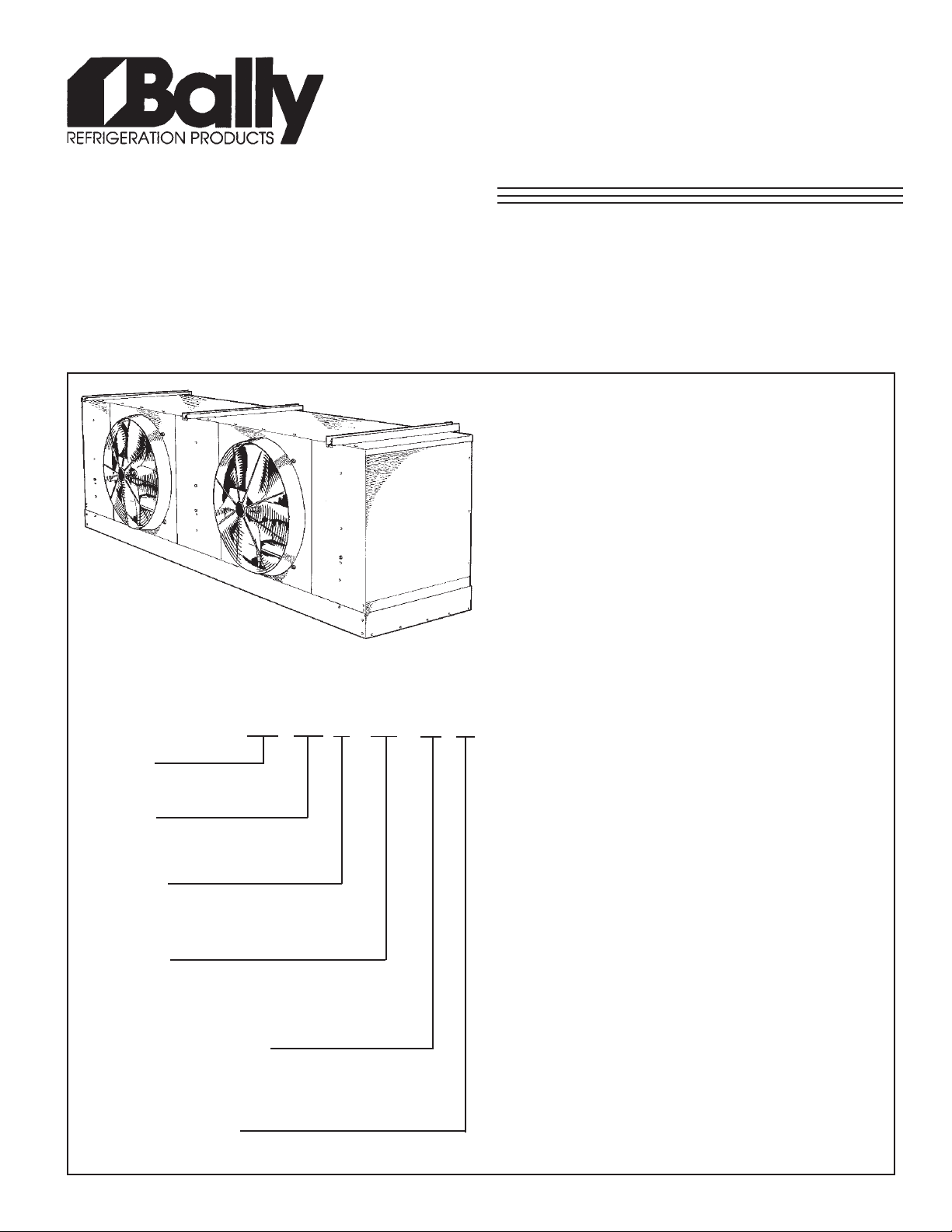
NOMENCLATURE
BC 160 S - ED - T3 A
BALLY
JUMBO BLAST COOLER
5 to 15 T ons at 10 °F (5.5 °C) T.D.
34 °F (1 °C) and Higher (Air Defrost)
-40 °F (-40 °C) and Above
(Medium and Low T emp)
Electrical Power: 208-230/3/60, 460/3/60,
575/3/60
• Incoloy defrost heaters mounted in slots on both sides
of cooling coils on electric defrost models.
• 3 - Pipe or reverse cycle hot gas defrost system.
• Factory installed hot gas check valve.
• Factory installed fan delay and defrost termination
thermostats on gas and electric defrost models.
• Hinged side panels allow easy access for refrigeration
circuit and electrical compartment.
• Schrader fitting and external equalizer line.
• Rugged high efficiency steel bladed fans.
• Plug-in motors with moulded lead and connector.
• Unit is shipped upright for convenient handling and
quick installation.
• Corrosion resistant, easy to clean vinyl coated fan
guards.
• Electrical terminals with recessed connections for
dependable operation.
CONTENTS
PAGE
MODEL
(DOES NOT NECESSARIL Y
REFLECT CAP ACITY)
OPTIONS
P = PRE ASSEMBLED REMOTE
S = STANDARD UNIT
DEFROST
ED = ELECTRIC DEFROST
H = 3 PIPE HOT GAS
R = REVERSE CYCLE HOT GAS
ELECTRICAL DESIGNA TION
T3 = 208-230/3/60
T4 = 460/3/60
T5 = 575/3/60
SERIES/GENERATION
A = 1st GENERA TION
Nomenclature.........................................
60Hz Capacity Data.................................
60Hz Air Flow Data..................................
Correction Factors.................................
60Hz Fan Motor Electrical Data.............
60Hz Defrost Heater Electrical Data.....
Refrigerant Charge................................
Air Defrost Wiring Diagram...................
Hot Gas Defrost Wiring Diagram..........
Electric Defrost Wiring Diagram...........
Refrigerant Piping Schematics............
Dimensions - Air & Electric Defrost.....
Dimensions - 3 Pipe Defrost &
Reverse Cycle Defrost Models.............
Installation Instructions.........................
Electrical & Refrigeration
Compartments........................................
Service Parts List...................................
Project Information................................
Cover
2
2
2
3
3
3
4
4
5
6
7
8, 9
10, 11
12, 13
14
Back
Page 2
SPECIFICATIONS (60Hz)
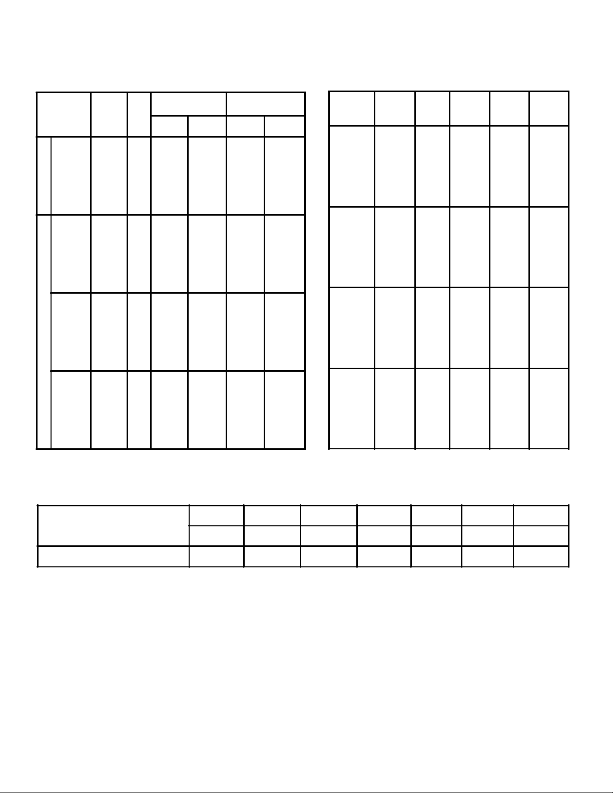
CAPACITY DATA (60Hz)
Fin
Model
BC085A
BC100A
BC115A
BC125A
BC140A
BC160A
BC180A
BC064*
BC077*
BC089*
BC101*
BC110*
BC126*
BC143*
BC059*
BC072*
BC085*
BC097*
BC103*
BC120*
BC138*
BC053*
BC066*
BC078*
BC091*
ELECTRIC AND HOT GAS DEFROST MODELS AIR DEFROST
BC094*
BC112*
BC129*
** No allowance made for fan heat - add 3,410 BTUH (1,000 watt) per HP to room load for motor heat.
* E = Electric Defrost • H = 3 Pipe Hot Gas Defrost • R = Reverse Cycle Hot gas Defrost
Spacing
No.
FPI
Fans
7 2 84.4 24.8 - 7 2 99.6 29.2 - 7 2 114.6 33.7 - 7 2 124.7 36.6 - 7 3 140.0 41.1 - 7 3 159.9 46.9 - 7 3 179.9 52.8 - 6 2 75.6 22.2 64.2 18.9
6 2 90.7 26.6 77.0 22.6
6 2 104.8 30.7 89.0 26.1
6 2 119.9 35.1 101.0 29.6
6 3 129.5 38.0 110.1 32.2
6 3 149.3 43.8 126.9 37.2
6 3 169.1 49.6 143.7 42.1
5 2 69.7 20.4 59.2 17.4
5 2 84.7 24.8 71.9 21.1
5 2 99.2 29.1 84.3 24.7
5 2 114.6 33.6 97.4 28.5
5 3 121.4 35.6 103.1 30.2
5 3 141.9 41.6 120.6 35.3
5 3 162.6 47.6 138.2 40.5
4 2 62.8 18.4 53.4 15.7
4 2 77.2 22.6 66.0 19.3
4 2 91.4 26.8 77.6 22.7
4 2 107.2 31.4 91.1 26.7
4 3 110.8 32.5 94.2 27.6
4 3 131.2 38.5 111.5 32.7
4 3 152.3 44.6 129.4 37.9
Capacity** at
of
20°F (-6.7°C)
MBH
10°F TDKW4.5°C TD
Capacity**at
-20°F (-28.9°C)
MBH
10°F TDKW4.5 °C TD
AIR FLOW DATA (60Hz)
Model
BC085A
BC100A
BC115A
BC125A
BC140A
BC160A
BC180A
BC064*
BC077*
BC089*
BC101*
BC110*
BC126*
BC143*
BC059*
BC072*
BC085*
BC097*
BC103*
BC120*
BC138*
BC053*
BC066*
BC078*
BC091*
BC094*
BC112*
BC129*
Fin
Spacing
FPI
7
7
7
7
7
7
7
6
6
6
6
6
6
6
5
5
5
5
5
5
5
4
4
4
4
4
4
4
CFM
17560
16480
15480
14600
23190
21630
20310
17860
16860
15920
15080
23910
22350
21000
18180
17260
16400
15580
24540
23100
21780
18520
17760
16880
16120
25230
23910
22650
THROW
(Ft.)
50
47
44
42
44
41
39
51
48
45
43
45
43
40
52
49
47
44
47
44
41
53
51
48
46
48
45
43
CFM
with
Booster
17560
16480
15480
14600
23190
21630
20310
17860
16860
15920
15080
23910
22350
21000
18180
17260
16400
15580
24540
23100
21780
18520
17760
16880
16120
25230
23910
22650
THROW
(Ft.)
91
86
80
77
80
75
71
93
88
83
78
83
77
73
95
89
86
80
86
80
75
97
93
88
84
88
82
78
EVAPORATOR TEMPERATURE CORRECTION FACTORS
Saturated Evaporator
Temperature
Correction Factor
20 °F 10 °F -0 °F -10 °F -20 °F -30 °F -40 °F
-6.7 °C -12.2 °C -17.8 °C -23.3 °C -28.9 °C -34.4 °C -40 °C
1.00 .98 .95 .91 .85 .79 .72
- 2 -
Page 3
FAN MOTOR ELECTRICAL DATA
AIR
DEFROST
MODEL
NO.
BC 085A 053 059 064
100A 066 072 077
115A 078 085 089
125A 091 097 101
BC 140A 094 103 110
160A 112 120 126
180A 129 138 143
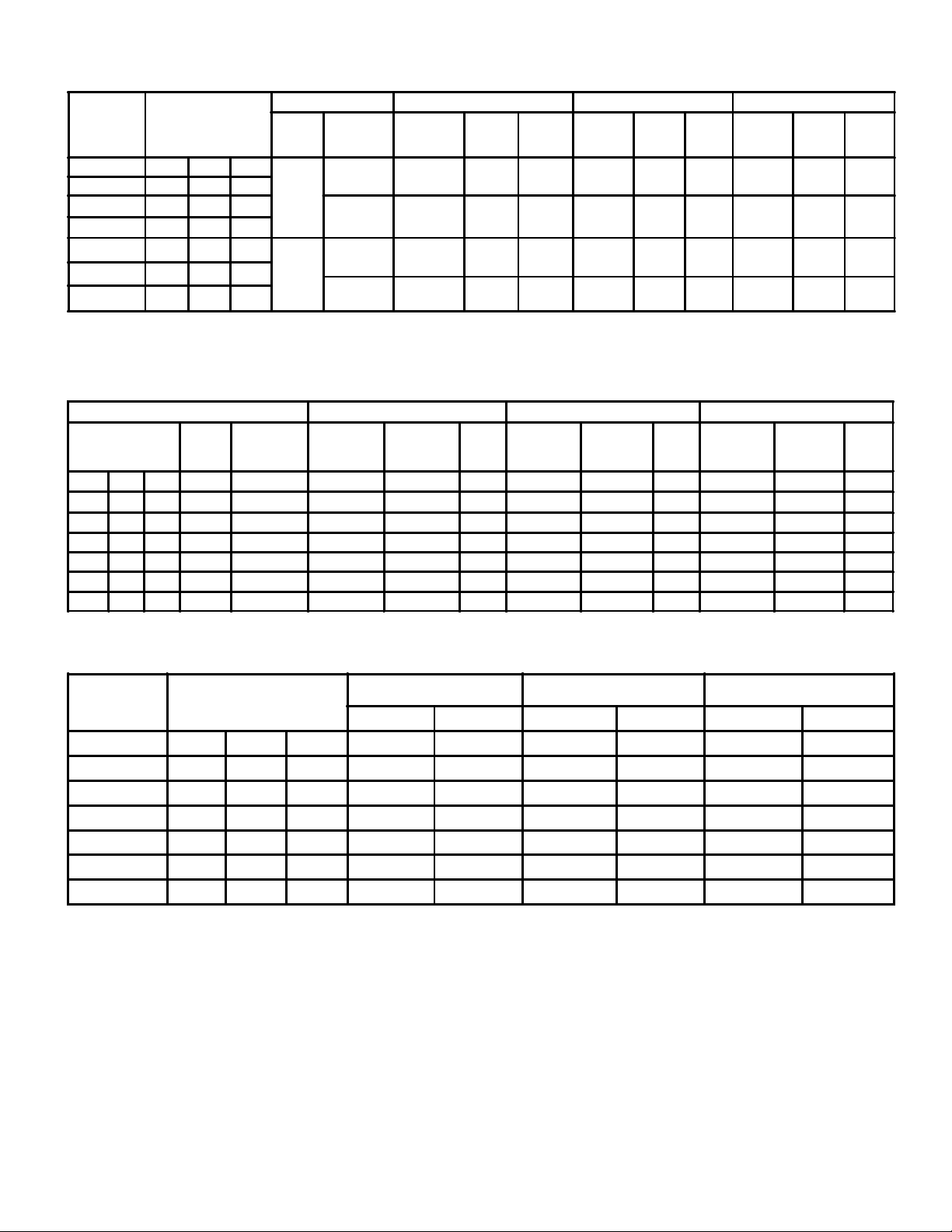
M.C.A. = Minimum Circuit Ampacity
M.O.P. = Maximum Overcurrent Protection
ELECTRIC
DEFROST
MODEL NO.
053 059 064
066 072 077
078 085 089
091 097 101
094 103 110
112 120 126
129 138 143
HOT GAS AND
ELECTRIC MODEL
NO.
Fan
Total heaterkWTotal
Motor
No.
2 14.0 38.1/42.2 40/48 50/60 21.1 24 30 16.9 20 25
2 19.6 48/53.1 48/56 60/70 26.5 28 35 21.2 24 30
2 22.4 57.2/63.3 64/64 80/80 31.6 32 40 25.3 28 35
2 22.4 57.2/63.3 64/64 80/80 31.6 32 40 25.3 28 35
3 22.4 57.2/63.3 64/64 80/80 31.6 32 40 25.3 28 35
3 25.2 57.2/63.3 64/64 80/80 31.6 32 40 25.3 28 35
3 28.0 67/74.1 72/80 90/100 37.0 40 50 29.6 32 40
Motor
Qty/HP
H 208-230/3/60 K 460/3/60 L 575/3/60
Fan
2/1
3/1
Type of
Motor
Std. Open
Drip Proof
Optional
TEFC
Std. Open
Drip Proof
Optional
TEFC
Total
F.L.A.
8.4 / 8.0 9.5 15 4.0 4.5 15 3.0 3.4 15
8.4 / 8.0 9.5 15 4.0 4.5 15 3.2 3.6 15
12.6 / 12.0
12.6 /12.0
M.C.A. M.O.P.
13.7
13.7
20
20
Total
F.L.A.
12.0
12.0
DEFROST HEATER ELECTRICAL DATA
H 208-230/3/60 K 460/3/60 L 575/3/60
F.L.A.
M.C.A. M.O.P.
Total
F.L.A.
M.C.A. M.O.P.
M.C.A. M.O.P.
13.0
13.02020
Total
F.L.A.
Total
F.L.A.
4.5
4.8
M.C.A. M.O.P.
4.9
5.2
M.C.A. M.O.P.
15
15
REFRIGERANT OPERATING CHARGE
AIR
DEFROST
MODEL NO.
085 053 059 064
100 066 072 077
115 078 085 089
125 091 097 101
140 094 103 110
160 112 120 126
180 129 138 143
Refrigerant charge with 30% full coil @ 20°F S.S.T.
HOT GAS AND ELECTRIC
DEFROST MODEL NO.
R-404A R-22 R-502
lb kg lb kg lb kg
35.2 16.0 39.1 17.8 40.4 18.3
46.1 21.0 51.4 23.4 53.0 24.1
57.2 26.0 63.7 29.0 65.6 29.8
68.2 31.0 75.9 34.5 78.2 35.6
63.7 29.0 71.0 32.3 73.2 33.3
76.9 35.0 85.6 38.9 88.3 40.1
92.4 42.0 102.8 46.7 106.0 48.2
- 3 -
Page 4
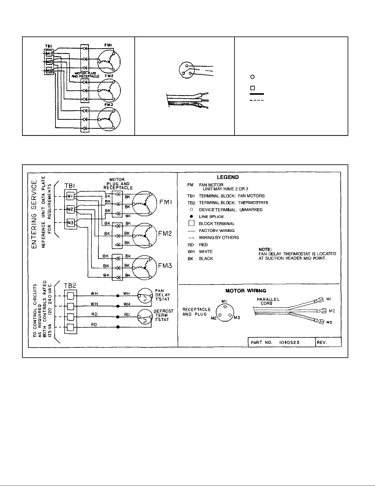
AIR DEFROST WIRING DIAGRAM
MOTOR WIRING
RECEPTACLE
AND PLUG
PARALLEL CORD
M1
M2
M3
M1
M2
M3
LEGEND
FM FAN MOTOR
TBI TERMINAL BLOCK
DEVICE TERMINAL
UNMARKED
BLOCK TERMINAL
FACTORY WIRING
WIRING BY OTHERS
REFERENCE UNIT DATA
PLATE FOR ENTERING
SERVICE REQUIREMENTS
HOT GAS DEFROST WIRING DIAGRAM
PART No. 1040309-B
- 4 -
Page 5
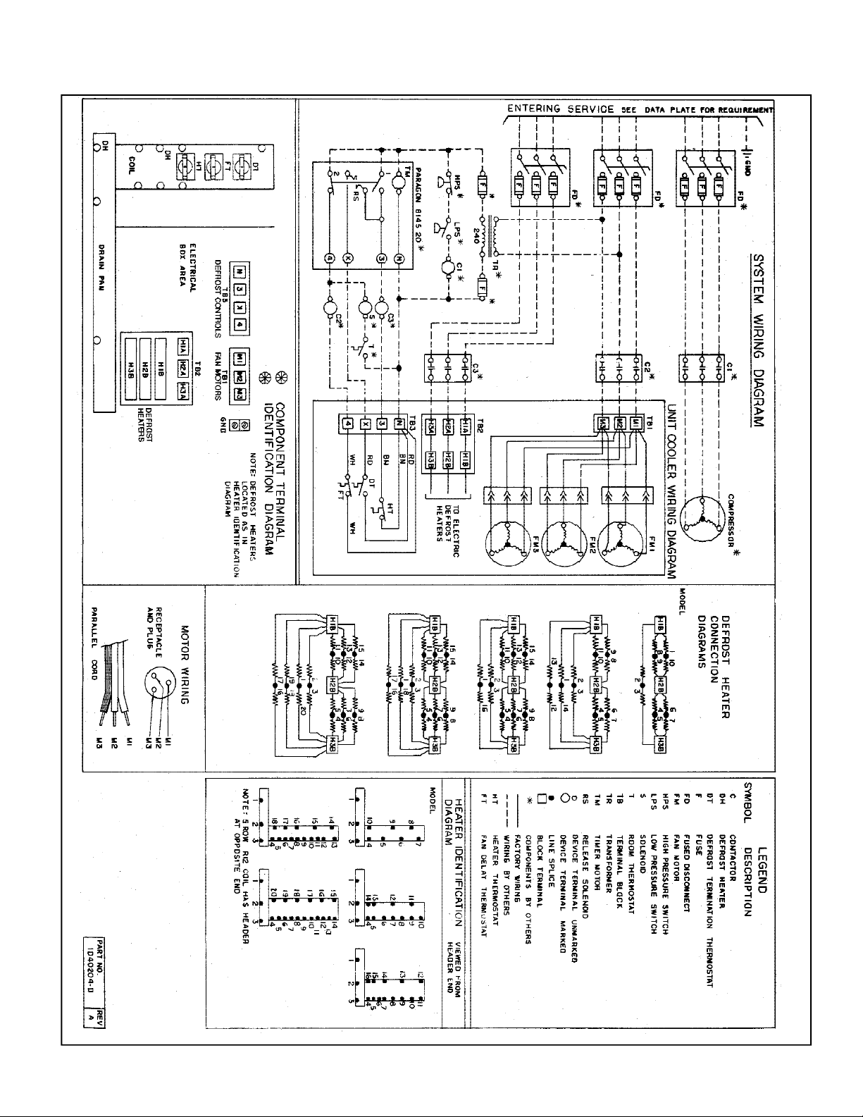
ELECTRIC DEFROST WIRING DIAGRAM
129
138
143
112
120
126
129
138
143
126
053
059
064
066
072
077
078
085
089
091
094
097
101
103
110
078
085
089
091
097
101
103
110112
120
077
053
059
064
066
072
- 5 -
Page 6
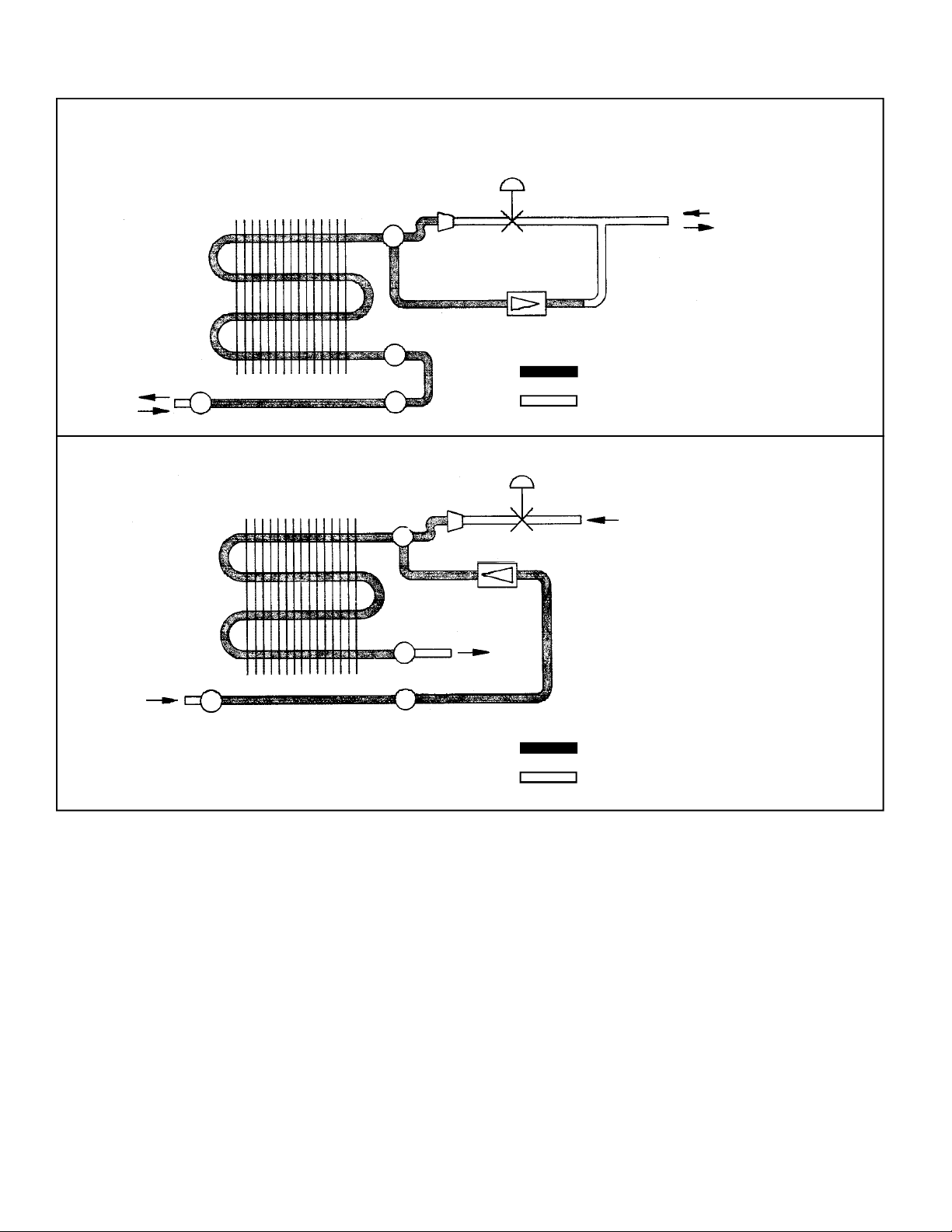
HOT GAS DEFROST REFRIGERATION PIPING SCHEMATICS
REVERSE CYCLE DEFROST SYSTEM
(1) THERMAL
EXPANSION
VALVE
LIQUID REFRIGERANT
LEAVING HOT GAS
(1) SUPPLIED AND INSTALLED BY CONTRACTOR
FACTORY INSTALLED PIPING
FIELD INSTALLED PIPING
(1) THERMAL
EXPANSION
VALVE
LIQUID REFRIGERANT
SUCTION
GAS
ENTERING
HOT GAS
EVAPORATOR COIL
DRAIN PAN DEFROST LOOP
3 - PIPE DEFROST SYSTEM
EVAPORATOR COIL
DISTRIBUTOR
CHECK VALVE
ENTERING
HOT GAS
DRAIN PAN DEFROST LOOP
CHECK VALVE
SUCTION
GAS
LEAVING
HOT GAS
(1) SUPPLIED AND INSTALLED BY CONTRACTOR
FACTORY INSTALLED PIPING
FIELD INSTALLED PIPING
- 6 -
Page 7
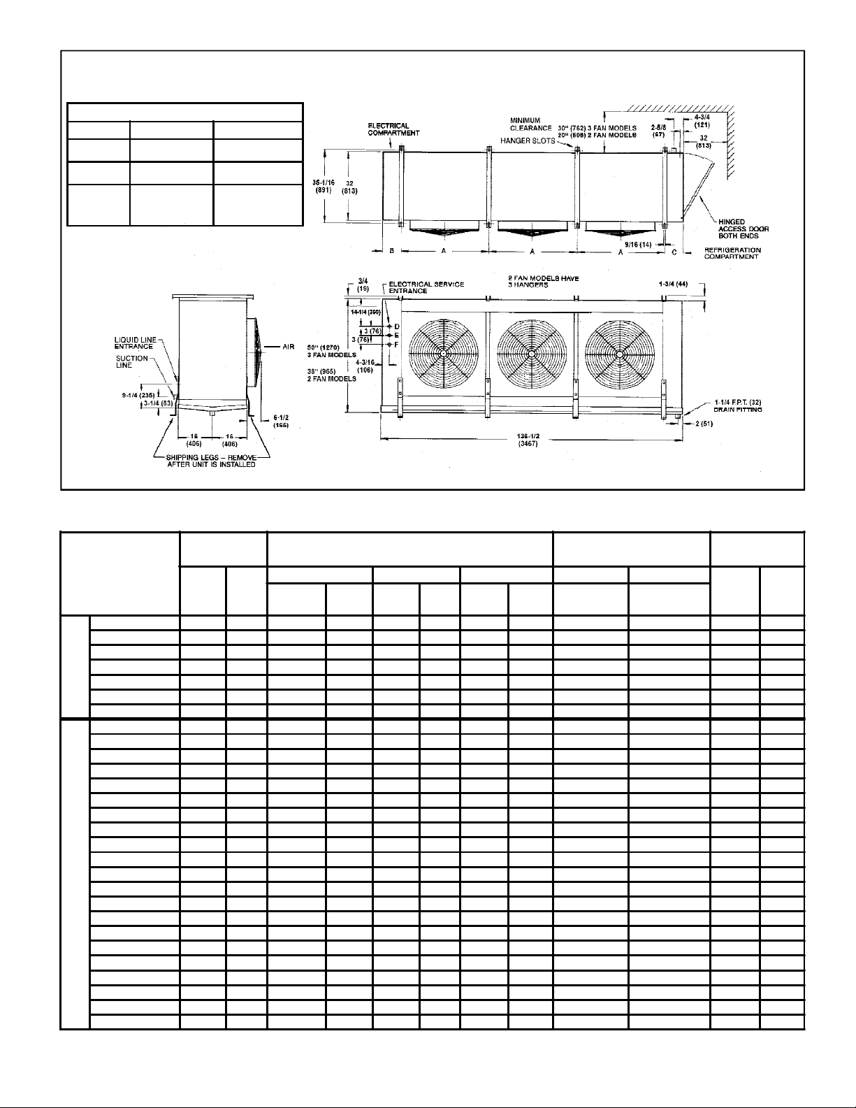
ELECTRICAL SERVICE ENTRANCE KNOCKOUTS
2 FAN MODELS 3 FAN MODELS
Motors - D
Controls - E
Heaters - F
7/8: Dia.
22mm
7/8" Dia.
22mm
1-3/32", 1-23/64"
& 1-23/32" Dia
22mm, 35mm &
44mm
7/8" & 1-3/32"Dia.
22mm & 28mm
7/8" Dia.
22mm
1-3/32", 1-23/64"
& 123/32" Dia.
22mm, 35mm &
44mm
AIR AND ELECTRIC DEFROST MODELS
MODEL
Inches mm
BC 085
BC 100
BC 115
BC 125
BC 140
BC 160
AIR DEFROST
BC 180
BC 064
BC 077
BC 089
BC 101
BC 110
BC 126
BC 143
BC 059
BC 072
BC 085
BC 097
BC 103
BC 120
BC 138
BC 053
BC 066
ELECTRIC DEFROST MODELS
BC 078
BC 091
BC 094
BC 112
BC 129
(1) O.D. in inches
DIMENSIONS AND WEIGHTS
HEIGHT HANGERS
A B C LIQUID SUCTION
Inches mm Inches mm Inches mm
38 965 60 1/16 1526 8 1/16 205 8 3/16 208 1 3/8 2 1/8 900 408
38 965 60 1/16 1526 8 1/16 205 8 3/16 208 1 3/8 2 1/8 1000 454
38 965 60 1/16 1526 8 1/16 205 8 3/16 208 1 3/8 2 1/8 1100 499
38 965 60 1/16 1526 8 1/16 205 8 3/16 208 1 3/8 2 1/8 1200 544
50 1270 40 1/16 1018 8 5/32 207 8 5/32 207 1 3/8 2 1/8 1300 590
50 1270 40 1/16 1018 8 5/32 207 8 5/32 207 1 3/8 2 1/8 1400 635
50 1270 40 1/16 1018 8 5/32 207 8 5/32 207 1 3/8 2 1/8 1500 680
38 965 60 1/16 1526 8 1/16 205 8 3/16 208 1 3/8 2 1/8 1030 467
38 965 60 1/16 1526 8 1/16 205 8 3/16 208 1 3/8 2 1/8 1100 499
38 965 60 1/16 1526 8 1/16 205 8 3/16 208 1 3/8 2 1/8 1200 544
38 965 60 1/16 1526 8 1/16 205 8 3/16 208 1 3/8 2 1/8 1300 590
50 1270 40 1/16 1018 8 5/32 207 8 5/32 207 1 3/8 2 1/8 1425 646
50 1270 40 1/16 1018 8 5/32 207 8 5/32 207 1 3/8 2 1/8 1550 703
50 1270 40 1/16 1018 8 5/32 207 8 5/32 207 1 3/8 2 1/8 1650 748
38 965 60 1/16 1526 8 1/16 205 8 3/16 208 1 3/8 2 1/8 1030 467
38 965 60 1/16 1526 8 1/16 205 8 3/16 208 1 3/8 2 1/8 1100 499
38 965 60 1/16 1526 8 1/16 205 8 3/16 208 1 3/8 2 1/8 1200 544
38 965 60 1/16 1526 8 1/16 205 8 3/16 208 1 3/8 2 1/8 1300 590
50 1270 40 1/16 1018 8 5/32 207 8 5/32 207 1 3/8 2 1/8 1425 646
50 1270 40 1/16 1018 8 5/32 207 8 5/32 207 1 3/8 2 1/8 1550 703
50 1270 40 1/16 1018 8 5/32 207 8 5/32 207 1 3/8 2 1/8 1650 748
38 965 60 1/16 1526 8 1/16 205 8 3/16 208 1 3/8 2 1/8 1030 467
38 965 60 1/16 1526 8 1/16 205 8 3/16 208 1 3/8 2 1/8 1100 499
38 965 60 1/16 1526 8 1/16 205 8 3/16 208 1 3/8 2 1/8 1200 544
38 965 60 1/16 1526 8 1/16 205 8 3/16 208 1 3/8 2 1/8 1300 590
50 1270 40 1/16 1018 8 5/32 207 8 5/32 207 1 3/8 2 1/8 1425 646
50 1270 40 1/16 1018 8 5/32 207 8 5/32 207 1 3/8 2 1/8 1550 703
50 1270 40 1/16 1018 8 5/32 207 8 5/32 207 1 3/8 2 1/8 1650 748
- 7 -
REFRIGERANT
CONNECTIONS (1)
R-12, R-22,
R-12, R-22,
R-502
UNIT WEIGHT
Lb. kg
R-502
Page 8
Motors A
Controls B
Electrical Service
Entrance Size
2 Fan 3 Fan
7/8" Dia.
22mm
7/8" Dia.
22mm
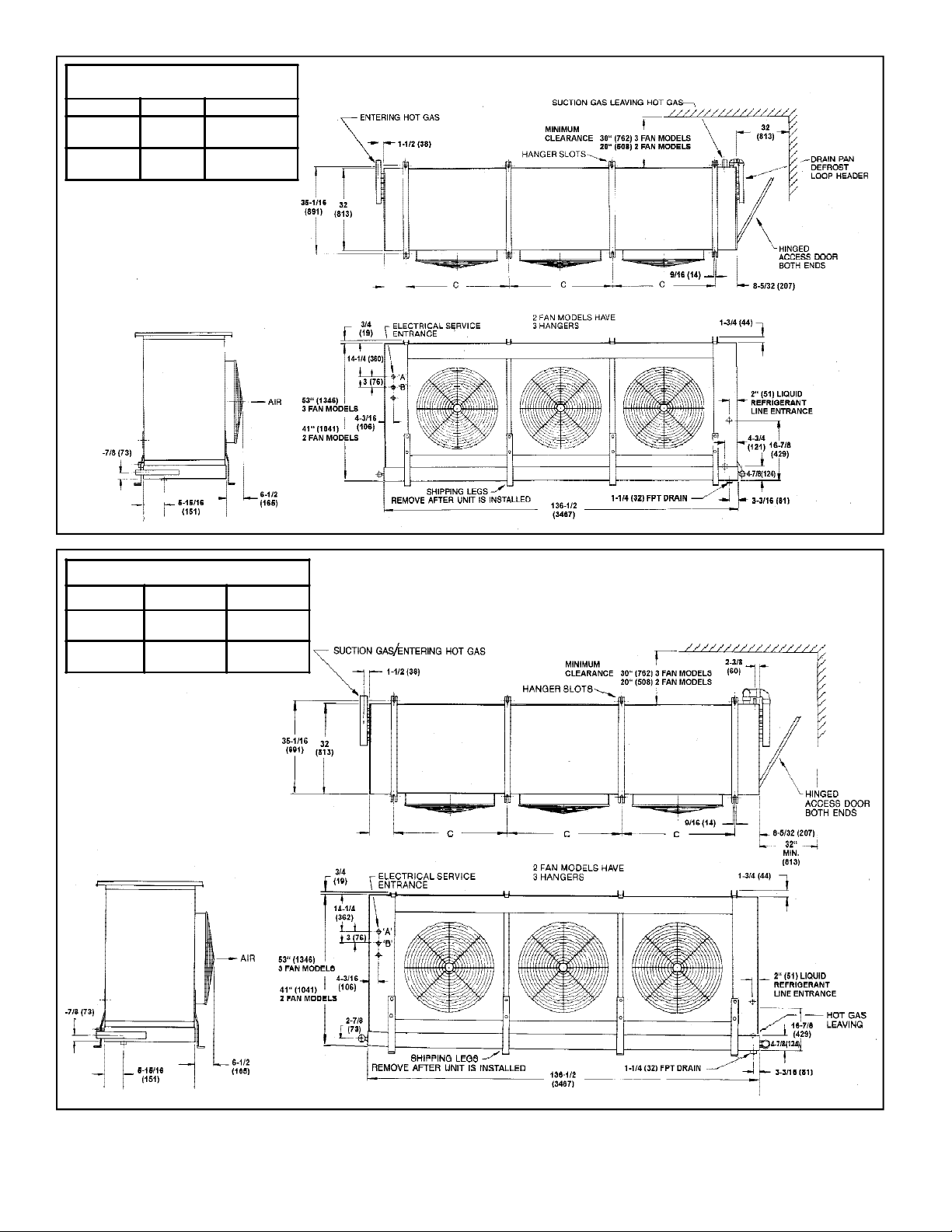
3 PIPE DEFROST MODEL
1-23/32" Dia.
44mm
1-23/32" Dia.
44mm
Electrical Service Entrance Knockouts
2 Fan Models 3 Fan Models
Motors - A
Controls - B
7/8"
22mm
7/8"
22mm
REVERSE CYCLE DEFROST MODEL
1-23/32"
44mm
1-23/32"
44mm
- 8 -
Page 9
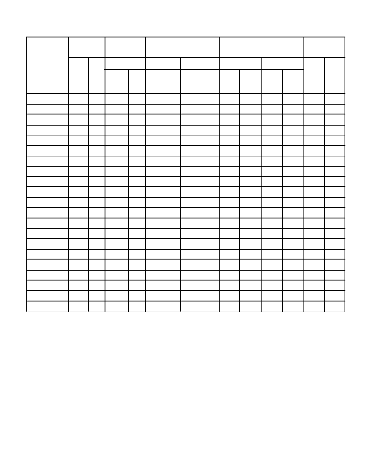
DIMENSIONS AND WEIGHTS
HOT GAS
DEFROST
MODEL
BC 064
BC 077
BC 089
BC 101
BC 110
BC 126
BC 143
BC 059
BC 072
BC 085
BC 097
BC 103
HEIGHT HANGERS
C LIQUID SUCTION 3-PIPE REVERSE
Inches mm
Inches mm
41 1041 60 1/16 1526 1 3/8 2 1/8 1 3/8 2 1/8 2 1/8 1 3/8 1055 479
41 1041 60 1/16 1526 1 3/8 2 1/8 1 3/8 2 1/8 2 1/8 1 3/8 1125 510
41 1041 60 1/16 1526 1 3/8 2 1/8 1 3/8 2 1/8 2 1/8 1 3/8 1225 556
41 1041 60 1/16 1526 1 3/8 2 1/8 1 3/8 2 1/8 2 1/8 1 3/8 1325 601
53 1346 40 1/16 1018 1 3/8 2 1/8 1 5/8 2 5/8 2 5/8 1 5/8 1450 658
53 1346 40 1/16 1018 1 3/8 2 1/8 1 5/8 2 5/8 2 5/8 1 5/8 1575 714
53 1346 40 1/16 1018 1 3/8 2 1/8 1 5/8 2 5/8 2 5/8 1 5/8 1675 760
41 1041 60 1/16 1526 1 3/8 2 1/8 1 3/8 2 1/8 2 1/8 1 3/8 1055 479
41 1041 60 1/16 1526 1 3/8 2 1/8 1 3/8 2 1/8 2 1/8 1 3/8 1125 510
41 1041 60 1/16 1526 1 3/8 2 1/8 1 3/8 2 1/8 2 1/8 1 3/8 1225 556
41 1041 60 1/16 1526 1 3/8 2 1/8 1 3/8 2 1/8 2 1/8 1 3/8 1325 601
53 1346 40 1/16 1018 1 3/8 2 1/8 1 5/8 2 5/8 2 5/8 1 5/8 1450 658
REFRIGERANT
CONNECTIONS (1)
R-22,
R-502
R-404A
R-404A
R-22,
R-502,
HOT GAS CONNECTIONS UNIT WEIGHT
Lb. kg
ENT. LVG. ENT. LVG.
BC 120
BC 138
BC 053
BC 066
BC 078
BC 091
BC 094
BC 112
BC 129
(1) O.D. in inches
53 1346 40 1/16 1018 1 3/8 2 1/8 1 5/8 2 5/8 2 5/8 1 5/8 1575 714
53 1346 40 1/16 1018 1 3/8 2 1/8 1 5/8 2 5/8 2 5/8 1 5/8 1675 760
41 1041 60 1/16 1526 1 3/8 2 1/8 1 3/8 2 1/8 2 1/8 1 3/8 1055 479
41 1041 60 1/16 1526 1 3/8 2 1/8 1 3/8 2 1/8 2 1/8 1 3/8 1125 510
41 1041 60 1/16 1526 1 3/8 2 1/8 1 3/8 2 1/8 2 1/8 1 3/8 1225 556
41 1041 60 1/16 1526 1 3/8 2 1/8 1 3/8 2 1/8 2 1/8 1 3/8 1325 601
53 1346 40 1/16 1018 1 3/8 2 1/8 1 5/8 2 5/8 2 5/8 1 5/8 1450 658
53 1346 40 1/16 1018 1 3/8 2 1/8 1 5/8 2 5/8 2 5/8 1 5/8 1575 714
53 1346 40 1/16 1018 1 3/8 2 1/8 1 5/8 2 5/8 2 5/8 1 5/8 1675 760
- 9 -
Page 10

INSTALLATION INSTRUCTIONS
INSPECTION
Careful inspection of all parts when received for loss or
damage in transit is very important - Remember, you, the
consignee, must make any claim necessary against the
transportation company. Shipping damage or missing
parts, when discovered at the outset, will prevent later
unnecessary and costly delays.
Ensure that the electrical characteristics are as ordered.
Save all tags and instruction sheets for reference by
installer and owner.
LOCATION
The unit location in the room should be selected to ensure
uniformair distribution throughout the entire space to be
refrigerated. Make sure that the fan does not blow directly
out or pull in through an opened door and that the product
does not obstruct the free circulation of air.
When installing the unit adjacent to a wall, sufficient
clearance must be provided to allow free air movement to
the coil.
Clearance must be provided at each end of the unit to
allow access to refrigerant piping and electrical
compartment.
See dimensional drawings for clearance requirements.
INSTALLATION
Note: These units draw air through the coil and
discharge air from the fan side (see P. 4).
JBC Unit Coolers are supplied with shipping legs to allow
units to be shipped in an upright position. Units are lifted
into place with shipping skid attached to mounting legs.
Slotted hanger brackets take 1/2” (12.7mm) hanger rods.
For fast, convenient mounting, install washer and nuts on
hanger rods prior to lifting units. Rods may be lifted into
slots and are held securely in place by tangs on hangers
After unit coolers are hung in place, remove shipping legs
from units by removing the two 5/16” (8mm) bolts from
each shipping leg.
Note: Shipping legs must be removed to allow hinged
drain pan to open.
DRAIN LINE
If unit cooler is mounted flush to ceiling, the staggered
heigh hanger will provide a positive pitch for drainage of
condenser.
If units are suspended below the ceiling, the installer
should provide adequate pitch to the unit by adjusting
the location of the hanger rod nuts.
Note: Check for adequate drainage by pouring water into
the drain pan.
Insulated copper tube should be run from the drain
connection, sloping at least 4” (102mm) per foot. A trap
outside of the room will prevent warm air entering
through the tubing. Connection should be made to
proper drainage facilities that comply with local
regulations.
If room temperatures are below freezing, it is necessary
to heat the drain line to prevent condensate from
freezing in the drain line. Electric heating cable or
electric tape (by others) is used for this purpose. The
drain line heater should be connected for continuous
operation; it is also recommended that the drain line be
insulated. A heat output of 20 watts per lineal foot of 1”
(25mm) drain line in a 0°F (-18 °C) room is usually
satisfactory. 115 volt cable and tape is available from
your local refrigeration wholesaler. Two 115 volts heaters
(by others) of the same wattage may be wired for use on
230 volt system
ELECTRICAL
Wire system in accordance with governing standards
and local codes. See wiring diagrams on P. 4 for unit
cooler wiring diagram.
Page 2 shows operating current, minimum ampacity and
maximum fuse sizing for fan motors.
Note: Electrical wiring is to be sized in accordance with
minimum ampacity rating.
The defrost termination thermostats, fan delay
thermostats and defrost heater safety thermostat are
factory supplied and factory wired to a terminal block.
See figure and component identification diagram on
wiring diagram for electrical compartment arrangement.
A hinged end panel provides quick access to the
electrical compartment.
- 10 -
Page 11

INSTALLATION INSTRUCTIONS
AFTER START UP
1. Check the oil level to be sure the oil charge is correct.
2. On the initial start up, the fans do not start until coil
temperature is pulled down to approximately 26 °F
(-3 °C)
Also, it is normal for the fans to cycle a few times
until the room temperature is pulled down.
Select an externally equalized expansion valve best
suited to the coil and the application on the basis of the
manufacturer’s ratings. Install the expansion valve in the
refrigeration piping compartment.
A 1/4” (6mm) O.D. equalizer line has been provided for
the externally equalized expansion valve connection.
3. After the room is pulled down make sure that the
expansion valve is properly set so that the coil frosts
evenly all the way through.
4. Heavy moisture loads are usually encountered when
starting the system for the first time. This will cause a
rapid build-up of frost on the unit cooler. During the
initial pull down, we suggest that the frost build-up be
watched and defrosted manually as required.
MAINTENANCE
1. Periodic checking and cleaning of the coil surface
when necessary should be done, using a whisk or
brush. Drain pans are hinged to provide convenient
access to the inside coil surface.
2. Motors are permanently lubricated type and require
no further lubrication.
REFRIGERATION SYSTEM
Refrigerant line sizes are important and should be the
same size as the coil connections, or larger, depending
on the length of run. Consult recommended refrigerant
line sizes charts (KeepRite Refrigeration Engineering
Manual or other recognized sources of information) when
sizing refrigerant lines.
Refrigerant piping and control systems should be
designed to prevent possible liquid slugging of the
compressors on start-up after the defrost cycle.
A Schrader valve fitting is supplied at the suction gas
header to provide convenient pressure readings.
The refrigerant distributor is sized and installed at the
factory and is supplied with a factory sized nozzle.
A hinged end panel provides quick access to the
refrigeration piping compartment.
SYSTEM CHECK
1. All wiring should be in accordance with local codes.
2. All refrigerant lines should be properly sized and
checked for any possible leaks.
3. Be sure system is charged with the proper refrigerant.
4. Make sure that the expansion valve thermal bulb is
securely strapped to the suction line.
5. The system should include a liquid line drier and
strainer.
6. The suction, discharge and receiver service valves
must be open.
7. Check that the fans turn freely and turn in clock wise
rotation.
8. Pour enough water into the drain pan to allow a good
check on drainage and seal the trap.
- 11 -
Page 12
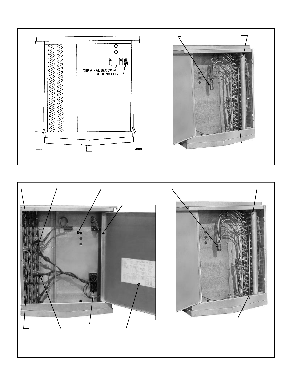
AIR DEFROST MODELS
FIGURE 2 - ELECTRICAL COMPARTMENT
ELECTRIC DEFROST MODELS
DISTRIBUTOR
SCHRADER
FITTING
EXTERNAL
EQUALIZER
LINE
FIGURE 3 - REFRIGERATION COMPARTMENT
COIL
DEFROST
HEATERS
FAN
DELAY
THERMOSTST
DEFROST
TERMINATION
THERMOSTAT
DEFROST
HEATER
SAFETY
THERMOSTAT
TB3 CONTROL CIRCUIT
TERMINAL BLOCK
TB2
DEFROST
HEATER
TERMINAL
BLOCK
TB1 FAN MOTOR
TERMINAL BLOCK
WIRING
DIAGRAM
DISTRIBUTOR
SCHRADER
FITTING
EXTERNAL
EQUALIZER
LINE
FIGURE 2 - ELECTRICAL COMPARTMENT
FIGURE 3 - REFRIGERATION COMPARTMENT
- 12 -
Page 13
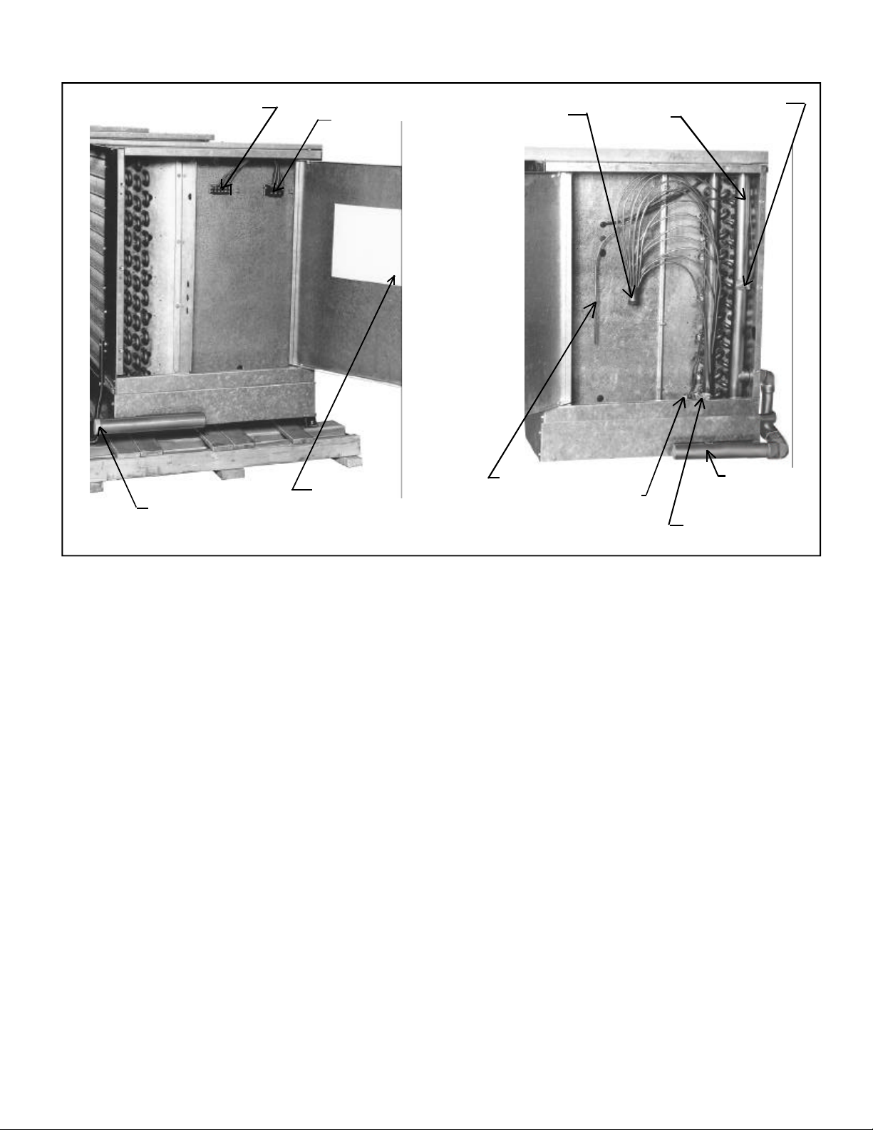
HOT GAS DEFROST MODELS
TB2 CONTROL CIRCUIT
TERMINAL BOX
DRAIN PAN HEADER
AND PIPING CONNECTION
TB1 FAN MOTOR
TERMINAL BLOCK
WIRING DIAGRAM
DISTRIBUTOR
EXTERNAL
EQUALIZER
LINE
SCHRADER
FITTING
DEFROST
TERMINATION
THERMOSTAT
FAN DELAY
THERMOSTAT
DRAIN PAN
HEADER
CHECK VALVE
- 13 -
Page 14
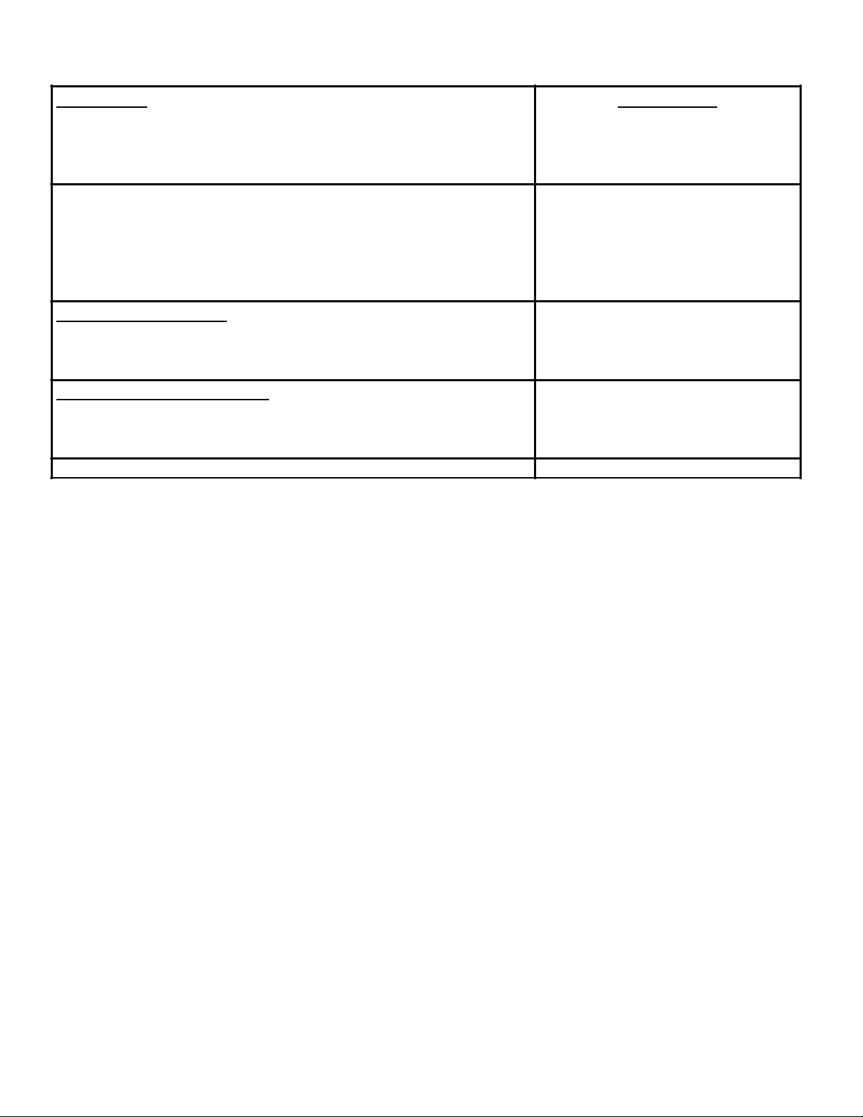
SERVICE PARTS LIST
FAN MOTORS
1 HP ODP 208-230/3/60
1 HP OPD 460/3/60
1 HP ODP 575/3/60
MOTOR MOUNT
FAN BLADE 30"
FAN MOTOR TERMINAL BLOCK TB1
DEFROST CONTROL TERMINAL BLOCK TB2
DEFROST HEATER TERMINAL BLOCK TB3
FAN DELAY THERMOSTAT
DEFROST TERMINATION THERMOSTAT
PART NUMBER
1040154
1040155
1040156
1040158
1040158
1040160
1040161
1040162
1040240
1040239
COIL DEFROST HEATERS
208-230/3/60
460/3/60
575/3/60
1040167
1040166
1040165
DRAIN PAN DEFROST HEATERS
208-230/3/60
460/3/60
575/3/60
THROW BOOSTER 1040695
1040167
1040166
1040165
- 14 -
Page 15

- 15 -
Page 16
PROJECT INFORMATION
01/10/05
metsyS
rebmuNledoM pU-tratSfoetaD
rebmuNlaireS rotcartnoCecivreS
tnaregirfeRenohP
ylppuSlacirtcelExaF
DISTRIBUTED BY:
General Sales, PGeneral Sales, P
General Sales, P
General Sales, PGeneral Sales, P
135 Little Nine Drive, Morehead City135 Little Nine Drive, Morehead City
135 Little Nine Drive, Morehead City
135 Little Nine Drive, Morehead City135 Little Nine Drive, Morehead City
252-240-2829 • 1-800-24-BALL252-240-2829 • 1-800-24-BALL
252-240-2829 • 1-800-24-BALL
252-240-2829 • 1-800-24-BALL252-240-2829 • 1-800-24-BALL
e-mail: ballysales@ballyrefboe-mail: ballysales@ballyrefbo
e-mail: ballysales@ballyrefbo
e-mail: ballysales@ballyrefboe-mail: ballysales@ballyrefbo
Due to Manufacturer’s policy of continuous product improvement, the Manufacturer reserves the right to make changes without notice.
arar
ts & Serts & Ser
ar
ts & Ser
arar
ts & Serts & Ser
vice Manufacturing & Engineeringvice Manufacturing & Engineering
vice Manufacturing & Engineering
vice Manufacturing & Engineeringvice Manufacturing & Engineering
xx
x
xx
, NC 28557, NC 28557
, NC 28557
, NC 28557, NC 28557
Y • FY • F
AX: 252-240-0384AX: 252-240-0384
Y • F
AX: 252-240-0384
Y • FY • F
AX: 252-240-0384AX: 252-240-0384
es.com • wwwes.com • www
es.com • www
es.com • wwwes.com • www
.ballyrefbo.ballyrefbo
.ballyrefbo
.ballyrefbo.ballyrefbo
xx
es.comes.com
x
es.com
xx
es.comes.com
.5 CP /00
 Loading...