

Page 1
®
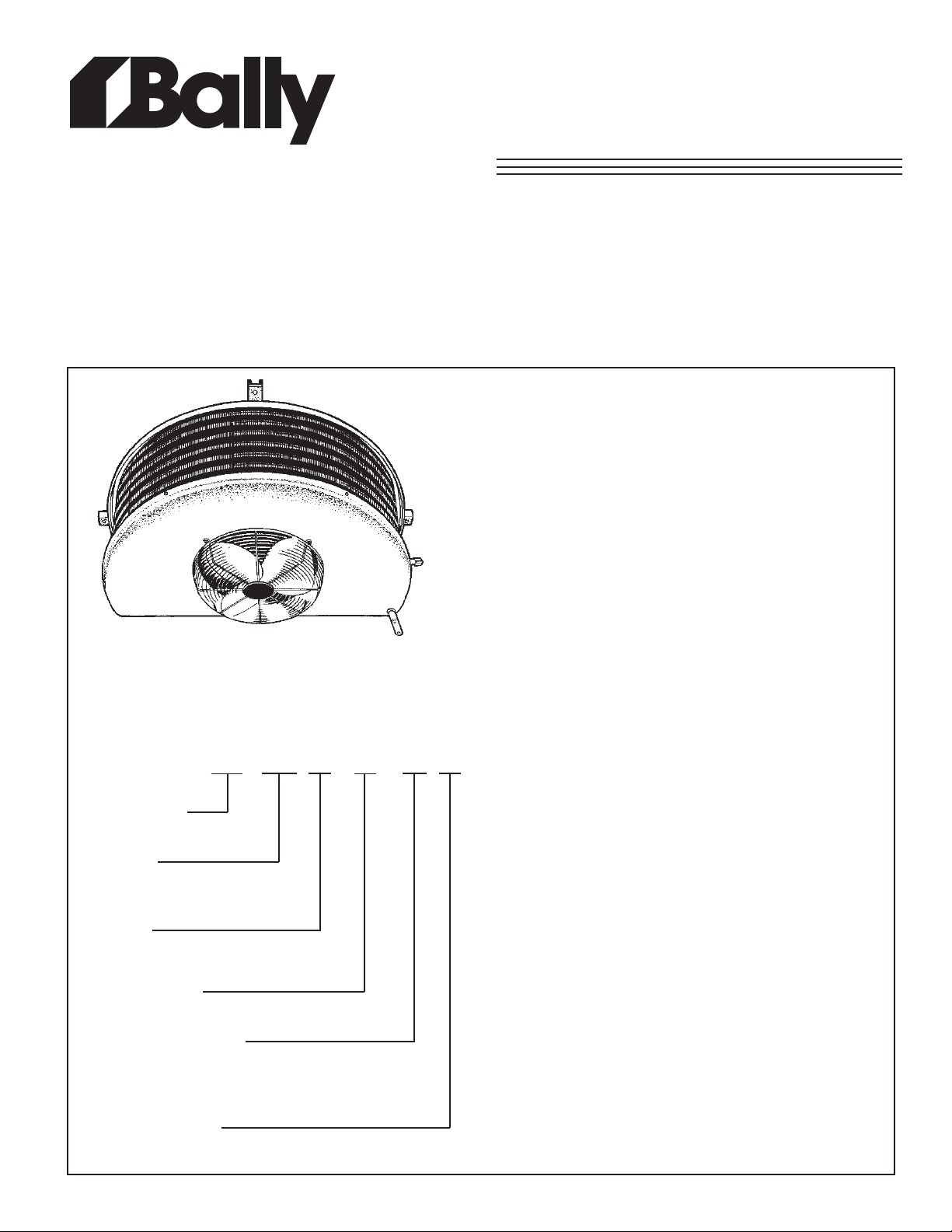
BR Half Round
Unit Coolers
PRODUCT DATA &
INSTALLATION
Bulletin B30-BR-PDI-14
1064604
High Temperature Applications
(35 °F and Higher)
Air Defrost
Electrical Power: 115/1/60
• Direct backwall location and minimum height provides
maximum usable storage space.
• Textured heavy gauge aluminum cabinet - lightweight,
doesn’t show scratches.
• Rigid, slotted channel hangers simplify installation.
• Hinged drain pan for ease of cleaning and service.
• Full collar aluminum plate fins on expanded seamless
copper tubes ensure optimum heat transfer efficiency.
NOMENCLATURE
BR 375 S - A - S2 A
Bally BR-Line
Half Round Unit Cooler
Capacity
BTUH @ 10
e.g. 450 = 4500 @ 10 oF TD
Options
S = Standard
P = Pre-assembled remote
T ype of Defrost
A = Air Defrost
Electrical Designation
S1 = 115/1/60
S6 = 220/1/50
Series/Generation
A = 1st Generation
o
F TD (60Hz) x 100
• Fan motors are inherently protected
CONTENTS PAGE
Nomenclature..........................................
Capacity Data...........................................
Electrical Data..........................................
T ypical Field Wiring.................................
Dimensinal & Physical Data....................
Thermostatic Expansion Valve..............
Installation Instructions..........................
Service Parts List....................................
Service Log..............................................
Warranty....................................................
Project Information.................................
“As Built” Service Parts.........................
Cover
Back
2
2
2
3
4
5
6
6
7
7
Page 2
CAP ACITY DAT A
SPECIFICATIONS
.oNLEDOM
573RB
584RB
8840685023707777.1
595RB
577RB
509RB
5201RB
5031RB
0502RB
* R-22 at 30 °F S.S.T. with coil 30% full
ELECTRICAL DATA
115/1/60 (SHADED POLE MOT OR)
LEDOM.YTQ.P.HMPR
573RB
102/105516.1251
584RB
102/105516.1251
595RB
102/105516.1251
577RB
151/105011.236.251
RB
509
151/105011.236.251
5201RB
151/105011.236.251
5031RB
151/105011.236.251
0502RB
251/105012.437.451
)HUTB(YTICAPAC
DTF°01RH/UTBF°21RH/UTBF°51.sbL*22R
WOLFRIA
MFC
03730844006507752.1
0
050606270809082101.2
0097084905811003120.3
00980860105331083182.3
002010422100351520
277.3
008210635100291000218.4
004020844200603050405.7
115/1/60 (OPTIONAL P .S.C. MOT OR)
LATOT
.A.L.F
.A.C.M.P.O.M
LEDOM.YTQ.P.HMPR
573RB
102/100616.057.051
584RB
102/100616.057.051
595RB
102/100616.057.051
577RB
151/106012
509RB
151/1060123.156.151
5201RB
151/1060123.156.151
5031RB
151/1060123.156.151
0502RB
251/1060146.279.251
M.C.A. = Minimum Circuit Ampacity
M.O.P . = Maximum Overcurrent Protection
LATOT
.A.L.F
3.156.151
EGRAHCG'RFER
.A.C.M.P.O.M
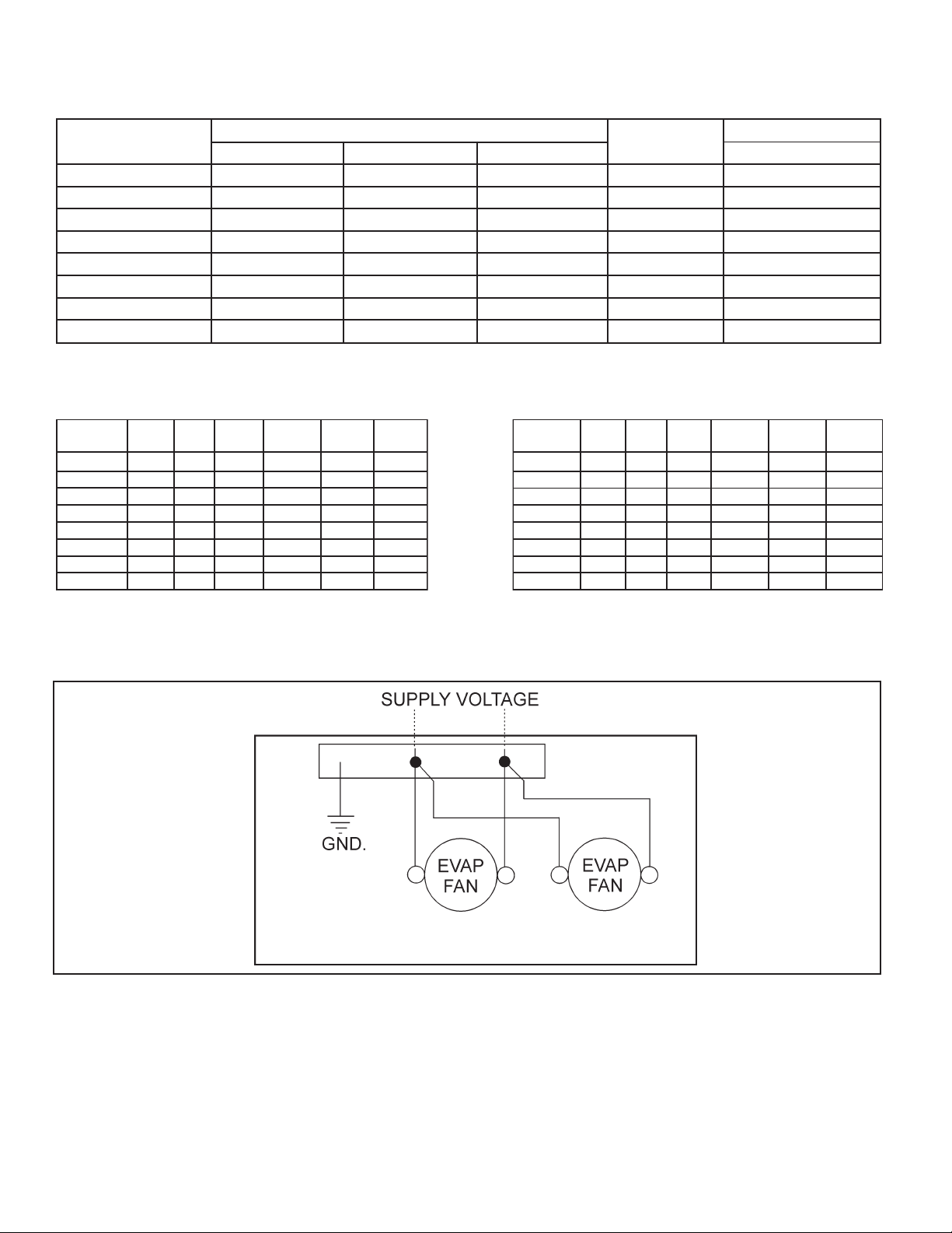
TYPICAL FIELD WIRING
2nd FAN MOT OR
ON R2050 MODEL
- 2 -
Page 3
1” (25mm)
AIR
FLOW
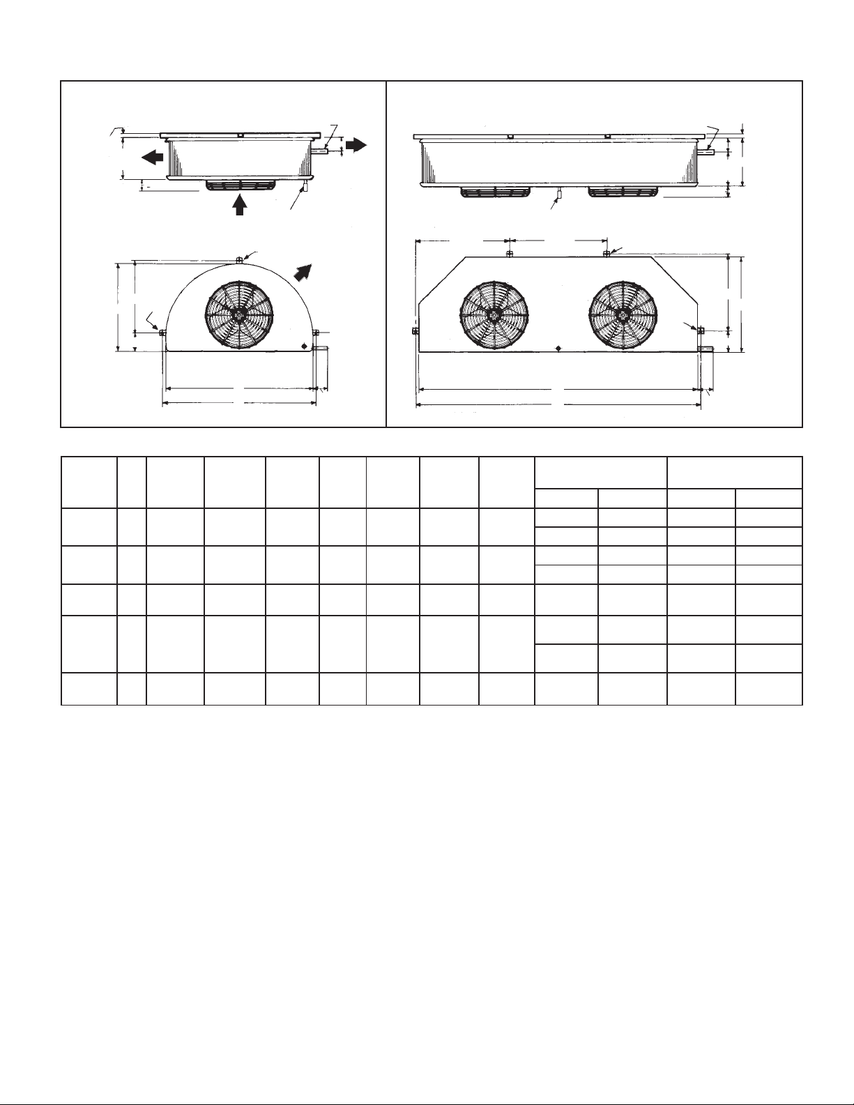
DIMENSIONAL AND PHYSICAL DA T A DA T A
MODEL R2050 (Double Fan)MODELS R375 to R1305 (Single Fan)
1” (25mm)
3 3/4”
(96mm)
D
E
A
C
3 3/4”
(96mm)
AIR
FLOW
15 FEET
THROW)
AIR
FLOW
EXTERNAL EQUALIZER CONNECTION
1/4” (5mm) O.D. (INSIDE CASING)
5/8” (16mm) O.D. DRAIN
WITH PLASTIC SLEEVE
24 7/8”
(632mm)
25 3/4
(654mm) 7/16” (11mm) DIA. HOLE
SUCTION
SUCTION
EXTERNAL EQUALIZER
CONNECTION
1/4” (5MM) O.D. (INSIDE CASING)
AIR
FLOW
7/16” (11mm) DIA. HOLE
7/16”
(11mm)
SLOT
E
C
G
5/8” (16mm) O.D. DRAIN
WITH PLASTIC SLEEVE
(APPROX.
B
F
4” (102mm)
MAX
LEDOMABCDEFG
573RB
ni
584RB
mm
595RB
ni
577RB
mm
ni
509RB
mm
8/18
)4.602(
8/111
)6.282(
8/111
)6.282(
4/133
)6.448(
4/193
)0.799(
4/124
)1.3
701(
4/302
2
)0.725(
4/332
)3.
306(
4/152
)4.146(
)8.05(
4/12
)2.75(
2/12
)5.36(
RB
5201
ni
RB
mm
8/521
)7.023(
4/
124
)1.3701(
4/152
2/12
)4.146(
)5.36(
5031
RB
ni
0502
mm
8/521
)7.023(
47
)6.9781(
4/152
2/12
)4.146(
)5.36(
NOTE: 5/8” (15.9 mm) O.D. Drain connection on all models.
1/2” (12.7 mm) Flare TX valve connection on all models R375 thru T775
1/2” (12.7 mm) Sweat TX Valve connection on models R905 thru R2050.
B
F
4” (102mm)
.D.O.nnoC.tcuS
MAX.
thgieWgnippihS
.sbL
nimm.sbL.gK
4/361
)5.524(
8/391
)1.294(
8/302
)5.714(
8/302
)5.714(
8/302
)5.714(
4/343
)7.288(
4/304
)0.5301(
4/334
)3.1111(
4/334
)3.1111(
2/157
)5.7191(
4/34
)7.021(
8/15
)2.031(
8/55
)9.241(
8/55
)9.241(
8/55
)9.241(
8/59.51277.23
8/59.51675.43
8/59.51895.44
8/72.224012.74
8/72.2280194
8/72.224112.15
8/72.224212.65
8/116.827818.48
- 3 -
Page 4

1RB
LEDOMF°DT
573RB
584RB
595RB
577RB
509RB
5201RB
503
0502RB
THERMOST A TIC EXPANSION V AL VE
SELECTION CHART FOR +35°F ROOMS AND UP
TSORFEDRIALEDOMEVLAVNALROPS LEDOMEVLAVOCLA
YTICAPAC
HUTB
01037,3C-3/1-EVGEES-4/1-ESGEC
21084,4C-3/1-EVGEES-2/1-ESGECJ-4/1-EJGECH-2/1-SEFHCS-4/1-SEFHCM-2/151006,5CV-2/1-EVGEES-2/1-ESGECJ-2/1-EJGECH-2/1-SEFHCS-4/1-SEFHCM-2/1-SEFH
01088,4CV-2/1-EVGEES-2/1-ESGEC
21068.5CV-2/1-EVGEES-2/1-ESGECJ-2/1-EJGECH-2/1-SEFHCS-2/1-SEFHCM-4/3
51023,7CV-4/3-EVGEES-2/1-ESGECJ-2/1-EJGECH-2/1-SEFHCS-2/1-SEFHCM-4/3-SEFH
01050,6CV-2/1-EVGEES-2/1-ESG
21062,7CV-4/3-EVGEES-2/1-ESGECJ-2/1-EJGECH-2/1-SEFHCS-2/1-SEFHCM-4/
51080,9CV-4/3-EVGEES-1-ESGECJ-1-EJGECH-1-SEFHCS-2/1-SEFHCM-4/3-SEFH
01009,7CV-4/3EVGEES-2/1-ESGECJ-2/1
210849CV-4/3EVGEES-1-ESGECJ-1-EJGECH-1-SEFHCS-1-SEFHCM-1-SEFH
51058,11CV-1-E
01009,8CV-4/3-EVGEES-1-ESGECJ-1-EJGECH-1-SEFHCS-1-SEFHCM-4/3
21086,01CV-1-EVGEES-1-ESGECJ-1-EJGECH-1-SEFHCS-1-SEFHCM-1-SEFH
51053,31CV-1-EVGEES-1-ESGECJ-1-EJGECH-1-SEFHCS01002,01CV-4/3-EVGEES-1-ESGECJ-1-EJGECH-1-SEFHCS-1-SEFHCM-1-SEFH
21042,21CV-1-EVGEES-1-ESGECJ
5103,51CV-2/11-EVGEES-1-ESGECJ-1-EJGECH-2/11-SEFHCS-4/11-SEFH
01008,21CV-1-EVGEES-1-ESGECJ-1-EJGECH-1-SEFHCS-4/11-SEFHCM-1-SEFH
21063,51CV-2/11-EVGEES-1-ESGECJ-1-EJGECH-2/11
51002,91CV-2/11-EVGEES-2/11-ESGECJ-2/11-EJGECH-2/11-SEFHCS-2/11-SEFH
01004,02CV-2/11-EVGEES-2/11-ESGECJ-2/11-EJGECH-2/11-SEFHCS-2/11-SEFH
21084,42CV-2-EVGEES-2-E
51006,03CV-3-EVGEES-3-ESGECJ-2-EJGECH-2/12-SEFHCS-2-SEFH
VGEES-1-ESGECJ-1-EJGECH-1-SEFHCS-1-SEFHCM-1-SEFH
TNAREGIRFER
22R
ECJ-2/1-EJGECH-2/1-SEFHCS-2/1-SEFHCM-4/3-SEFH
SGECJ-2/11-EJGECH-2-SEFHCS-2-SEFH
TNAREGIRFER
705/A404/205R
REGIRFER
TNA
a431R/21R
J-6/1-EJGECH-4/1-SEFHCS-4/1-SEFHCM-2/1-SEFH
J-2/1-EJGECH-2/1-SEFHCS-4/1-SEFHCM-2/1-SEFH
-EJGECH-2/1-SEFHCS-2/1-SEFHCM-4/3-SEFH
-1-EJGECH-1-SEFHCS-1-SEFHCM-1-SEFH
TNAREGIRFER
22R
-SEFHCS-4/11-SEFH
TNAREGIRFER
705/A404/205R
1-SEFHCM-1-SEFH
SEFH
-SEFH
-SEFH
M
H
TNAREGIRFER
a431R
3-SEFH
-2/11-SEFH
CM
-2/11-SEFH
CM
-4/31-SEFH
C
-4/31-SEFH
CM
-2/12-SEFH
CM
-2/12-SEF
CM
Selections based on 100° Liquid
- 4 -
Page 5

APPLICATION
High Temp Unit Coolers are designed for use with R12, R22,
R134a, R404A, R407A/B/C, R507 or R502 refrigerants.
At room temperatures above 34
lower than 27
accomplish the defrost. Temperatures of 34
-40
°F) require positive defrosting. (either Electric or Hot Gas).
The coil must not be exposed to any abnormal atmospheric
or acidic environments. This may result in corrosion to the
cabinet and possible coil failure (leaks). (Consult
manufacturer for optional baked on phenolic protective
coatings).
°F the air flowing through the coil will
°F and evaporating temps no
°F and below (to
INSTALLATION
The installation and start-up of Unit Coolers should only be
performed by qualified refrigeration mechanics.
This equipment should be installed in accordance with all
applicable codes, ordinances and local by-laws.
INSPECTION
Inspect all equipment before unpacking for visible signs of
damage or loss. Check shipping list against material
received to ensure shipment is complete.
IMPORTANT: Remember, you, the consignee, must make any
claim necessary against the transportation company.
Shipping damage or missing parts, when discovered at the
outset, will prevent later unnecessary and costly delays.
If damage or loss during transport is evident, make claim
to carrier, as this will be their responsibility , not the
manufacturer’s.
Should carton be damaged, but damage to equipment is not
obvious, a claim should be filed for “concealed damage” with
the carrier.
IMPORTANT: The electrical characteristics of the unit should
be checked at this time to make sure they correspond to
those ordered and to electrical power available at the job
site.
Save all shipping papers, tags and instruction sheets for
reference by installer and owner.
LOCATION
The unit location in the room should be selected to ensure
uniform air distribution throughout the entire space to be
refrigerated. Make sure that the air is not blown directly out
through the opened door and that the product does not
obstruct the free circulation of air.
NOTE: These units drawn air through the fan and discharge
air from the coil side.
MOUNTING
Mounting brackets with 7/16” dia holes are provided for flush
mounting to the ceiling. For details refer to dimensional data
on page 3.
Ensure that the ceiling is level since the drain pan has been
sloped for drainage during the defrost cycle.
DRAIN LINE
The drain line should be run from the drain connection,
sloping at least 4” per foot. A trap outside the room will
prevent warm air from entering through the tubing.
Connection should be made to proper drainage facilities that
comply with local regulations.
Ensure that the drain pan has sufficient slope for proper
drainage (prevention of ice build up/blockage in pan).
PIPING
Refrigerant line sizes are important and may not be the same
size as the coil connections. (depends on the length of run) If
in doubt, consult “Recommended refrigerant line sizes”
charts. (Engineering Manuals or other recognized sources of
information).
WIRING
Wire system in accordance with governing standards and
local codes. See data and wiring diagram on page 2, for
wiring arrangement. Electrical wiring is to be sized in
accordance with minimum ampacity rating.
SYSTEM CHECK
Before Start-Up:
1. All wiring should be in accordance with local codes.
2. Refrigerant lines should be properly sized.
3. Off-cycle defrost systems should include a liquid line
solenoid valve.
4. Thorough evacuation and, dehydration has been
performed.
5. The suction, discharge, and receiver service valves must
be open.
6. The system should include a liquid line drier moisture
indicator and suction filter.
7. Pour enough water into the drain pan to allow a good check
on drainage and seal the trap.
After Start-Up:
1. Check the compressor oil level to ensure the correct oil
charge.
2. Be sure that the expansion valve is properly set to provide
the correct amount of superheat.
3. Heavy moisture loads are usually encountered when
starting the system for the first time.
4. Check for proper evaporator fan blade rotation.
When installing the unit adjacent to a wall sufficient
clearance (2” (50mm) minimum) must be provided to allow
the hinged drain pan to be lowered for servicing the unit.
Channel type hangers are provided. Rear hangers are
slotted to facilitate installation. See dimensional data.
MAINTENANCE
The unit should be periodically inspected for any dirt or
build-up on the fin surface and cleaned if necessary with a
soft whisk or brush.
- 5 -
Page 6

SERVICE PARTS LIST
SROTOMNAF
LEDOM
.P.SV511.C.S.PV511
EDALBNAFDRAUGNAF
573RB
584RB
95RB
5
577RB
509RB
5201RB
5031RB
0502RB
1260713352601172823403401
1260713352601172823403401
126071335260107282300-215071
026071145260127282300-215071
026071145260196282300-215071
0260711
026071145260196282300-215071
026071145260196282300-215071
45260196282300-215071
SERVICE LOG
ETADSTNEMMOC
- 6 -
Page 7

FINISHED GOODS WARRANTY
The terms and conditions as described below in the General Warranty Policy cover all products
manufactured by National Refrigeration.
GENERAL WARRANTY POLICY
Subject to the terms and conditions hereof, the Company warrants all Products, including Service
Parts, manufactured by the Company to be free of defects in material or workmanship, under normal
use and application for a period of one (1) year from the original date of installation, or eighteen (18)
months from the date of shipment from the Company, whichever occurs first. Any replacement
part(s) so supplied will be warranted for the balance of the product’s original warranty. The part(s) to
be replaced must be made available in exchange for the replacement part(s) and reasonable proof of
the original installation date of the product must be presented in order to establish the effective date
of the warranty , failing which, the ef fective date will be based upon the date of manufacture plus thirty
(30) days. Any labour, material, refrigerant, transportation, freight or other charges incurred in connection with the performance of this warranty will be the responsibility of the owner at the current
rates and prices then in effect. This warranty may be transferred to a subsequent owner of the
product.
THIS WARRANTY DOES NOT COVER
(a) Damages caused by accident, abuse, negligence, misuse, riot, fire, flood, or Acts of God (b) damages
caused by operating the product in a corrosive atmosphere (c) damages caused by any unauthorized
alteration or repair of the system affecting the product’s reliability or performance (d) damages caused
by improper matching or application of the product or the product’s components (e) damages caused
by failing to provide routine and proper maintenance or service to the product (f) expenses incurred for
the erecting, disconnecting, or dismantling the product (g) parts used in connection with normal
maintenance, such as filters or belts (h) products no longer at the site of the original installation (i)
products installed or operated other than in accordance with the printed instructions, with the local
installation or building codes and with good trade practices (j) products lost or stolen.
No one is authorized to change this WARRANTY or to create for or on behalf of the Company any
other obligation or liability in connection with the Product(s). There is no other representation, warranty
or condition in any respect, expressed or implied, made by or binding upon the Company other than the
above or as provided by provincial or state law and which cannot be limited or excluded by such law , nor
will we be liable in any way for incidental, consequential, or special damages however caused.
The provisions of this additional written warranty are in addition to and not a modification of or subtraction
from the statutory warranties and other rights and remedies provided by Federal, Provincial or State
laws.
PROJECT INFORMATION
metsyS
rebmuNledoM pU-tratSfoetaD
rebmuNlaireS rotcartnoCecivreS
tnaregirfeRenohP
ylppuSlacirtcelExaF
- 7 -
Page 8

“AS BUILT” SERVICE PARTS LIST
04/14/2008
Service Parts ListService Parts List
Service Parts List
Service Parts ListService Parts List
LL
abelabel
L
abel
LL
abelabel
TT
o Be Ao Be A
T
o Be A
TT
o Be Ao Be A
HEREHERE
HERE
HEREHERE
ttachedttached
ttached
ttachedttached
®
General Sales, PGeneral Sales, P
General Sales, P
General Sales, PGeneral Sales, P
135 Little Nine Drive, Morehead City135 Little Nine Drive, Morehead City
135 Little Nine Drive, Morehead City
135 Little Nine Drive, Morehead City135 Little Nine Drive, Morehead City
252-240-2829 • 1-800-24-BALL252-240-2829 • 1-800-24-BALL
252-240-2829 • 1-800-24-BALL
252-240-2829 • 1-800-24-BALL252-240-2829 • 1-800-24-BALL
e-mail: ballysales@ballyrefboe-mail: ballysales@ballyrefbo
e-mail: ballysales@ballyrefbo
e-mail: ballysales@ballyrefboe-mail: ballysales@ballyrefbo
Due to Manufacturer’s policy of continuous product improvement,
the Manufacturer reserves the right to make changes without notice.
arar
ts & Serts & Ser
ar
ts & Ser
arar
ts & Serts & Ser
vice Manufacturing & Engineeringvice Manufacturing & Engineering
vice Manufacturing & Engineering
vice Manufacturing & Engineeringvice Manufacturing & Engineering
xx
x
xx
, NC 28557, NC 28557
, NC 28557
, NC 28557, NC 28557
Y • FY • F
AX: 252-240-0384AX: 252-240-0384
Y • F
AX: 252-240-0384
Y • FY • F
es.com • wwwes.com • www
es.com • www
es.com • wwwes.com • www
AX: 252-240-0384AX: 252-240-0384
.ballyrefbo.ballyrefbo
.ballyrefbo
.ballyrefbo.ballyrefbo
xx
es.comes.com
x
es.com
xx
es.comes.com
DISTRIBUTED BY:
 Loading...