

Page 1
BQZ-Line
01/15/11
CondensingUnits
PRODUCTDATA&
SPECIFICATIONS
BulletinB40-BQZ-PDS-1
1090652
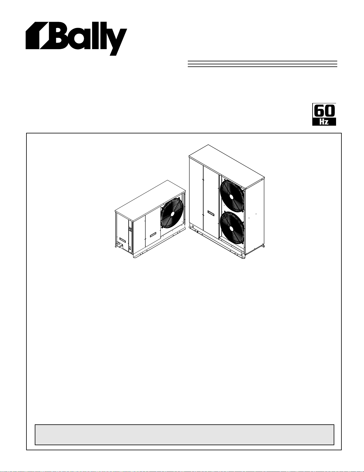
Outdoor Air-Cooled
Scroll Condensing Units
1 to 6 HP -
Medium and Low
Temperature Refrigeration
CONTENTS
Page
Nomenclature.....................................................................................................................
Features and Options ........................................................................................................
Capacity Data (Imperial and Metric)...................................................................................
Electrical Data....................................................................................................................
Dimensional Data...............................................................................................................
Specications.....................................................................................................................
Sound Data........................................................................................................................
Wiring Diagrams ...............................................................................................................
EC Motor Application.........................................................................................................
Generic Service Parts List..................................................................................................
Warranty.............................................................................................................................
Project Information.............................................................................................................
“As Built” Service Parts List................................................................................................
For the latest product updates and further information, visit www.ballyrefboxes.com
11 - 13
14 - 16
2
2 - 3
4 - 7
8
9
10
10
17
19
19
BACK
Page 2

ModelName
B40-BQZ-PDS-1
- 2 -
01/15/11
B = Bally
NOMENCLATURE
BQZA030H8-HT3A
Series
A = Latest Catalog Series
ModelSeries
QZ = Quiet Scroll Air Cooled Condensing Unit Line
CompressorManufacturer
A = Copeland
NominalHP
010 - 060 = 1 - 6 HP
ApplicationRange
H = High and Med Temp
M = Med Temp
E = Extended Medium Temperature
L = Low Temp
• Heavy duty weatherproof construction
• High efciency enhanced tube and n condenser design
• High efciency EC variable speed motor as head pressure control
• Receiver with fusible plug and liquid shut-off valve
• Liquid injection (low temperature models)
• Adjustable low pressure control and xed high pressure control
• Discharge thermostat on applicable models only
Voltage*
S2 = 208/230-1-60* S3 = 230-1-60
S6 = 200/220-1-50 S7 = 200-1-50*
T3 = 208/230-3-60 T4 = 460-3-60
T7 = 200/220-3-50 T9 = 380/400-3-50
STANDARDFEATURES
• Copeland Scroll compressors
• Painted cabinet
TM
• Gold Coat
• Crankcase heater
• Time delay relay
ns
Enclosure
H = Outdoor
Refrigerant*
6 = R404A / R507*
7 = R407C
8 = R404A / R507 / R22 / R407C
*subjecttocompressoravailability
OPTIONALACCESSORIES
• Sealed liquid line lter drier and sight glass
• Suction accumulator
• Sealed suction lter
• Heated and insulated receiver - required in ambients below 10°F
• Non-fused disconnect switch
• Pump down toggle switch
• Mechanical time clock
• Sound insulated compressor compartment *
• Wall mount kit
• Oil seperator (2 fan models only)
* see sound data table on page 10
Page 3

OPTIONALFEATUREPACKAGES
B40-BQZ-PDS-1
- 3 -
01/15/11
(FactoryMounted)
Package A:
• Standard Features (see pg. 2)
Package B:
• Standard Features (see pg. 2)
• Plus Sealed Liquid Line Filter Drier & Sight Glass
Package C:
• Standard Features (see pg. 2)
• Plus Sealed Liquid Line Filter Drier & Sight Glass
• Plus Suction Accumulator
• Plus Mechanical Time Clock
Package D:
• Standard Features (see pg. 2)
• Plus Sealed Liquid Line Filter Drier & Sight Glass
• Plus Heated and Insulated Receiver
(required in ambients below 10°F)
Package E:
• Standard Features (see pg. 2)
• Plus Sealed Liquid Line Filter Drier & Sight Glass
• Plus Heated and Insulated Receiver
(required in ambients below 10°F)
• Plus Suction Accumulator
• Plus Mechanical Time Clock
Package F:
• Standard Features (see pg. 2)
• Plus Sealed Liquid Line Filter Drier & Sight Glass
• Plus Mechanical Time Clock
Package G:
• Standard Features (see pg. 2)
• Plus Sealed Liquid Line Filter Drier & Sight Glass
• Plus Heated and Insulated Receiver
(required in ambients below 10°F)
• Plus Mechanical Time Clock
Package H:
• Standard Features (see pg. 2)
• Plus Sealed Liquid Line Filter Drier & Sight Glass
• Plus Suction Accumulator
• Plus Heated and Insulated Receiver
(required in ambients below 10°F)
Package J:
• Standard Features (see pg. 2)
• Plus Sealed Liquid Line Filter Drier & Sight Glass
• Plus Compressor Compartment Sound Insulation
Package K:
• Standard Features (see pg. 2)
• Plus Sealed Liquid Line Filter Drier & Sight Glass
• Plus Compressor Compartment Sound Insulation
• Plus Mechanical Time Clock
Page 4

BQZA
B40-BQZ-PDS-1
- 4 -
01/15/11
COPELAND
CAPACITYDATA-
R404A
R507
HIGH/MEDIUMTEMPERATURE
60Hz
SATURATED
MODEL
BQZA020H8 30 (-1.1) 22770 (6672) 21870 (6408) 20960 (6141) 20030 (5869) 19090 (5593) 18120 (5309) 17150 (5025)
Compressor 15 (-9.4) 17540 (5139) 16840 (4934) 16150 (4732) 15440 (4524) 14700 (4307) 13950 (4087) 13190 (3865)
Model 10 (-12.2) 15960 (4676) 15340 (4495) 14700 (4307) 14050 (4117) 13390 (3923) 12710 (3724) 12000 (3516)
ZB15KCE 5 (-15) 14480 (4243) 13910 (4076) 13340 (3909) 12750 (3736) 12150 (3560) 11520 (3375) 10880 (3188)
BQZA025H8 30 (-1.1) 27280 (7993) 26160 (7665) 25020 (7331) 23870 (6994) 22680 (6645) 21480 (6294) 20250 (5933)
Compressor 15 (-9.4) 21170 (6203) 20310 (5951) 19440 (5696) 18530 (5429) 17610 (5160) 16660 (4881) 15700 (4600)
Model 10 (-12.2) 19320 (5661) 18540 (5432) 17730 (5195) 16920 (4958) 16080 (4711) 15210 (4457) 14320 (4196)
ZB19KCE 5 (-15) 17570 (5148) 16860 (4940) 16130 (4726) 15380 (4506) 14620 (4284) 13830 (4052) 13010 (3812)
BQZA030H8 30 (-1.1) 32430 (9502) 31090 (9109) 29730 (8711) 28340 (8304) 26930 (7890) 25490 (7469) 24020 (7038)
Compressor 15 (-9.4) 25200 (7384) 24170 (7082) 23110 (6771) 22040 (6458) 20940 (6135) 19800 (5801) 18640 (5462)
Model 10 (-12.2) 23010 (6742) 22070 (6467) 21
ZB21KCE 5 (-15) 20930 (6132) 20080 (5883) 19200 (5626) 18310 (5365) 17390 (5095) 16440 (4817) 15470 (4533)
BQZA035H8 30 (-1.1) 40390 (11840) 38820 (11380) 37230 (10910) 35610 (10440) 33960 (9950) 32290 (9460) 30580 (8960)
Compressor 15 (-9.4) 31000 (9090) 29800 (8730) 28580 (8380) 27330 (8010) 26060 (7640) 24770 (7260) 23440 (6870)
Model 10 (-12.2) 28180 (8260) 27100 (7940) 26000 (7620) 24860 (7290) 23710 (6950) 22520 (6600) 21300 (6240)
ZB26KCE 5 (-15) 25550 (7490) 24570 (7200) 23570 (6910) 22540 (6610) 21490 (6300) 20410 (5980) 19300 (5660)
BQZA040H8 30 (-1.1) 46520 (13630) 44700 (13100) 42850 (12560) 40960 (12000) 39040 (11440) 37080 (10870) 35080 (10280)
Compressor 15 (-9.4) 35460 (10390) 34080 (9990) 32670 (9570) 31230 (9150) 29740 (8720) 28220 (8270) 26660 (7810)
Model 10 (-12.2) 32140 (9420) 30890 (9050) 29600 (8670) 28290 (8290) 26930 (7890) 25540 (7490) 24110 (7070)
ZB30KCE 5 (-15) 29010 (8500) 27870 (8170) 26700
BQZA050H8 30 (-1.1) 55670 (16320) 53460 (15670) 51200 (15010) 48910 (14330) 46570 (13650) 44190 (12950) 41770 (12240)
Compressor 15 (-9.4) 43000 (12600) 41300 (12100) 39560 (11590) 37790 (11080) 35980 (10540) 34130 (10000) 32220 (9440)
Model 10 (-12.2) 39190 (11490) 37640 (11030) 36070 (10570) 34450 (10100) 32790 (9610) 31100 (9110) 29350 (8600)
ZB38KCE 5 (-15) 35570 (10420) 34190 (10020) 32750 (9600) 31290 (9170) 29780 (8730) 28230 (8270) 26640 (7810)
BQZA060H8 30 (-1.1) 65430 (19180) 62800 (18400) 60120 (17620) 57410 (16830) 54640 (16010) 51830 (15190) 48950 (14350)
Compressor 15 (-9.4) 50640 (14840) 48630 (14250) 46570 (13650) 44460 (13030) 42300 (12400) 40100 (11750) 37830 (11090)
Model 10 (-12.2) 46180 (13530) 44340 (12990) 42470 (12450) 40550 (11880) 38580 (11310) 36560 (10710) 34480 (10110)
ZB45KCE 5 (-15) 41950 (12290) 40290 (11810) 38590 (11310) 36840 (10800) 35060 (10280) 33210 (9730) 31310 (9180)
SUCTION
TEMP.
F° (C°)
40 (4.4) 26690 (7820) 25640 (7513) 24570 (7199) 23490 (6883) 22390 (6560) 21270 (6232) 20130 (5898)
35 (1.7) 24700 (7237) 23720 (6950) 22730 (6660) 21720 (6364) 20710 (6068) 19670 (5763) 18610 (5453)
25 (-3.9) 20940 (6135) 20120 (5895) 19280 (5649) 18420 (5397) 17560 (5145) 16660 (4881) 15760 (4618)
20 (-6.7) 19190 (5623) 18440 (5403) 17670 (5177) 16880 (4946) 16090 (4714) 15280 (4477) 14440 (4231)
0 (-17.8) 13080 (3832) 12580 (3686) 12050 (3531) 11530 (3378) 10970 (3214) 10410 (3050) 9830 (2880)
-5 (-20.6)
40 (4.4) 31790 (9314) 30480 (8931) 29160 (8544) 27810 (8148) 26450 (7750) 25050 (7340) 23650 (6929)
35 (1.7) 29490 (8641) 28280 (8286) 27050 (7926) 25800 (7559) 24530 (7187) 23240 (6809) 21910 (6420)
25 (-3.9) 25150 (7369) 24120 (7067) 23070 (6760) 22010 (6449) 20920 (6130) 19800 (5801) 18670 (5470)
20 (-6.7) 23110 (6771) 22180 (6499) 21210 (6215) 20220 (5924) 19230 (5634) 18200 (5333) 17150 (5025)
0 (-17.8) 15910 (4662) 15280 (4477) 14620 (4284) 13930 (4081) 13240 (3879) 12520 (3668) 11770 (3449)
-5 (-20.6)
40 (4.4) 37770 (11067) 36200 (10607) 34620 (10144) 33010 (9672) 31370 (9191) 29720 (8708) 28020 (8210)
35 (1.7) 35050 (10270) 33600 (9845) 32130 (9414) 30630 (8975) 29110 (8529) 27560 (8075) 25980 (7612)
25 (-3.9)
20 (-6.7) 27500 (8058) 26380 (7729) 25220 (7389) 24050 (7047) 22850 (6695) 21610 (6332) 20350 (5963)
0 (-17.8) 18960 (5555) 18200 (5333) 17400 (5098) 16590 (4861) 15750 (4615) 14890 (4363) 14000 (4102)
-5 (-20.6)
40 (4.4) 47470 (13910) 45620 (13370) 43750 (12820) 41850 (12260) 39930 (11700) 37970 (11130) 35980 (10540)
35 (1.7) 43850 (12850) 42150 (12350) 40410 (11840) 38660 (11330) 36880 (10810) 35060 (10280) 33210 (9730)
25 (-3.9) 37100 (10870) 35660 (10450) 34200 (10020) 32710 (9590) 31200 (9140) 29640 (8690) 28070 (8230)
20 (-6.7) 33960 (9950) 32640 (9570) 31310 (9180) 29950 (8780) 28560 (8370) 27140 (7950) 25680 (7530)
0 (-17.8) 23070 (6760) 22190 (6500) 21280 (6240) 20360 (5970) 19400 (5690) 18430 (5400) 17410 (5100)
-5 (-20.6)
40 (4.4) 54770 (16050) 52630 (15420) 50440 (14780) 48230 (14130) 45970 (13470) 43670 (12800) 41330 (12110)
35 (1.7) 50560 (14820) 48580 (14240) 46570 (13650) 44520 (13050) 42430 (12430) 40310 (11810) 38140 (11180)
25 (-3.9) 42650 (12500) 40990 (12010) 39290 (11510) 37560 (11010) 35790 (10490) 33990 (9960) 32140 (9420)
20 (-6.7) 38970 (11420) 37450 (10980) 35900 (10520) 34310 (10060) 32700 (9580) 31040 (9100) 29340 (8600)
0 (-17.8) 26060 (7640) 25020 (7330) 23950 (7020) 22860 (6700) 21720 (6370) 20560 (6030) 19360 (5670)
-5 (-20.6)
40 (4.4) 651
35 (1.7) 60290 (17670) 57890 (16970) 55450 (16250) 52960 (15520) 50440 (14780) 47880 (14030) 45270 (13270)
25 (-3.9) 51250 (15020) 49200 (14420) 47130 (13810) 45020 (13190) 42870 (12560) 40680 (11920) 38430 (11260)
20 (-6.7) 47020 (13780) 45150 (13230) 43250 (12680) 41320 (12110) 39330 (11530) 37320 (10940) 35250 (10330)
0 (-17.8) 32180 (9430) 30920 (9060) 29630 (8680) 28310 (8300) 26940 (7900) 25530 (7480) 24070 (7050)
-5 (-20.6)
40 (4.4) 76400 (22390) 73320 (21490) 70200 (20570) 67040 (19650) 63830 (18710) 60560 (17750) 57250 (16780)
35 (1.7) 70810 (20750) 67960 (19920) 65070 (19070) 62130 (18210) 59150 (17340) 56100 (16440) 53010 (15540)
25 (-3.9) 60270 (17660) 57860 (16960) 55400 (16240) 52890 (15500) 50340 (14750) 47730 (13990) 45070 (13210)
20 (-6.7) 55350 (16220) 53130 (15570) 50870 (14910) 48570 (14230) 46220 (13550) 43820 (12840) 41360 (12120)
0 (-17.8) 37970 (11130) 36470 (10690) 34930 (10240) 33360 (9780) 31730 (9300) 30050 (8810) 28320 (8300)
-5 (-20.6)
80 (26.6) 85 (29.4) 90 (32.2) 95 (35.0) 100 (37.8) 105 (40.6) 110 (43.3)
11780 (3452) 11320 (3317) 10860 (3182) 10370 (3038) 9880 (2895) 9370 (2745) 8830 (2587)
14350 (4205) 13780 (4038) 13190 (3865) 12570 (3683) 11940 (3498) 11290 (3308) 10610 (3109)
29910 (8764) 28690 (8406) 27430 (8037) 26150 (7662) 24840 (7278) 23510 (6888) 22140 (6487)
17100 (5010) 16410 (4808) 15710 (4603) 14970 (4386) 14210 (4164) 13420 (3932) 12610 (3695)
20750 (6080) 19960 (5850) 19140 (5610) 18310 (5370) 17450 (5110) 16560 (4850) 15630 (4580)
23290 (6830) 22330 (6540) 21370 (6260) 20360 (5970) 19320 (5660) 18260 (5350) 17160 (5030)
10 (19080) 62510 (18320) 59870 (17550) 57200 (16760) 54480 (15970) 51720 (15160) 48920 (14340)
28990 (8500) 27870 (8170) 26700 (7820) 25500 (7470) 24270 (7110) 22980 (6730) 21650 (6340)
34220 (10030) 32880 (9640) 31490 (9230) 30060 (8810) 28590 (8380) 27070 (7930) 25480 (7470)
CAPACITYBTU/H(WATTS)
110 (6185) 20130 (5898) 19110 (5599) 18080 (5297) 17010 (4984)
(7820) 25490 (7470) 24260 (7110) 22980 (6730) 21670 (6350)
R404AR507
AMBIENTTEMPERATURE°F(°C)
Page 5

BQZA
B40-BQZ-PDS-1
- 5 -
01/15/11
COPELAND
CAPACITYDATA-
R407C
HIGH/MEDIUMTEMPERATURE
60Hz
MODEL
BQZA020H8
Compressor
Model
ZB15KCE
BQZA025H8
Compressor
Model
ZB19KCE
BQZA030H8
Compressor
Model
ZB21KCE
BQZA035H8
Compressor
Model
ZB26KCE
BQZA040H8
Compressor
Model
ZB30KCE
BQZA050H8
Compressor
Model
ZB38KCE
BQZA060H8
Compressor
Model
ZB45KCE
SATURATED
SUCTION
TEMP.
°F ° C
45 (7.2) 27500 (8060) 26700 (7820) 25900 (7590) 25000 (7330) 24200 (7090) 23300 (6830) 22400 (6560)
40 (4.4) 25200 (7390) 24400 (7150) 23700 (6950) 22900 (6710) 22100 (6480) 21300 (6240) 20400 (5980)
35 (1.7) 23000 (6740) 22300 (6540) 21600 (6330) 20900 (6130) 20100 (5890) 19300 (5660) 18500 (5420)
30 (-1.1) 20900 (6130) 20200 (5920) 19600 (5740) 18900 (5540) 18200 (5330) 17500 (5130) 16800 (4920)
25 (-3.9) 18900 (5540) 18300 (5360) 17700 (5190) 17100 (5010) 16500 (4840) 15800 (4630) 15100 (4430)
20 (-6.7) 17100 (5010) 16500 (4840) 16000 (4690) 15400 (4510) 14800 (4340) 14200 (4160) 13500 (3960)
15 (-9.4) 15400 (4510) 14900 (4370) 14400 (4220) 13800 (4040) 13300 (3900) 12700 (3720) 12100 (3550)
10 (-12.2) 13800 (4040) 13300 (3900) 12800 (3750) 12300 (3600) 11800 (3460) 11300 (3310) 10700 (3140)
45 (7.2) 30100 (8820) 29200 (8560) 28200 (8260) 27200 (7970) 26100 (7650) 25000 (7330) 23900 (7000)
40 (4.4) 27400 (8030) 26600 (7800) 25700 (7530) 24700 (7240) 23800 (6980) 22800 (6680) 21700 (6360)
35 (1.7) 24800 (7270) 24100 (7060) 23200 (6800) 22400 (6560) 21500 (6300) 20600 (6040) 19700 (5770)
30 (-1.1) 22400 (6560) 21700 (6360) 21000 (6150) 20200 (5920) 19400 (5690) 18600 (5450) 17800 (5220)
25 (-3.9) 20100 (5890) 19500 (5710) 18800 (5510) 18100 (5300) 17500 (5130) 16700 (4890) 16000 (4690)
20 (-6.7) 18000 (5280) 17400 (5100) 16800 (4920) 16200 (4750) 15600 (4570) 15000 (4400) 14400 (4220)
15 (-9.4) 16000 (4690) 15500 (4540) 15000 (4400) 14400 (4220) 13900 (4070) 13400 (3930) 12800 (3750)
10 (-12.2) 14200 (4160) 13700 (4020) 13300 (3900) 12800 (3750) 12400 (3630) 11900 (3490) 11400 (3340)
45 (7.2) 37800 (11080) 36600 (10730) 35400 (10370) 34100 (9990) 32800 (9610) 31400 (9200) 30100 (8820)
40 (4.4) 34600 (10140) 33500 (9820) 32400 (9500) 31200 (9140) 30000 (8790) 28800 (8440) 27500 (8060)
35 (1.7) 31600 (9260) 30600 (8970) 29500 (8650) 28500 (8350) 27400 (8030) 26300 (7710) 25100 (7360)
30 (-1.1) 28700 (8410) 27800 (8150) 26800 (7850) 25900 (7590) 24900 (7300) 23900 (7000) 22800 (6680)
25 (-3.9) 26000 (7620) 25200 (7390) 24300 (7120) 23400 (6860) 22500 (6590) 21600 (6330) 20700 (6070)
20 (-6.7) 23400 (6860) 22700 (6650) 21900 (6420) 21100 (6180) 20300 (5950) 19500 (5710) 18700 (5480)
15 (-9.4) 21100 (6180) 20400 (5980) 19700 (5770) 19000 (5570) 18300 (5360) 17500 (5130) 16800 (4920)
10 (-12.2) 18800 (5510) 18200 (5330) 17600 (5160) 17000 (4980) 16300 (4780) 15700 (4600) 15000 (4400)
45 (7.2) 47100 (13800) 45800 (13420) 44400 (13010) 43100 (12630) 41600 (12190) 40100 (11750) 38500 (1
40 (4.4) 43300 (12690) 42100 (12340) 40800 (11960) 39500 (11580) 38100 (11170) 36600 (10730) 35100 (10290)
35 (1.7) 39500 (11580) 38400 (11250) 37200 (10900) 35900 (10520) 34600 (10140) 33200 (9730) 31800 (9320)
30 (-1.1) 35800 (10490) 34700 (10170) 33600 (9850) 32500 (9520) 31200 (9140) 30000 (8790) 28600 (8380)
25 (-3.9) 32300 (9470) 31300 (9170) 30300 (8880) 29200 (8560) 28000 (8210) 26800 (7850) 25600 (7500)
20 (-6.7) 29000 (8500) 28100 (8240) 27100 (7940) 26100 (7650) 25100 (7360) 24000 (7030) 22900 (6710)
15 (-9.4) 26100 (7650) 25200 (7390) 24400 (7150) 23500 (6890) 22500 (6590) 21500 (6300) 20500 (6010)
10 (-12.2) 23500 (6890) 22800 (6680) 22000 (6450) 21200 (6210) 20400 (5980) 19500 (5710) 18600 (5450)
45 (7.2) 53300 (15620) 51900 (15210) 50500 (14800) 49000 (14360) 47400 (13890) 45800 (13420) 44200 (12950)
40 (4.4) 48600 (14240) 47300 (13860) 46000 (13480) 44600 (13070) 43100 (12630) 41700 (12220) 40200 (11780)
35 (1.7) 44200 (12950) 43000 (12600) 41700 (12220) 40400 (11840) 39100 (11460) 37800 (11080) 36400 (10670)
30 (-1.1) 40000 (11720) 38900 (11400) 37700 (11050) 36600 (10730) 35400 (10370) 34100 (9990) 32900 (9640)
25 (-3.9) 36100 (10580) 35100 (10290) 34000 (9960) 33000 (9670) 31900 (9350) 30700 (9000) 29600 (8670)
20 (-6.7) 32500 (9520) 31600 (9260) 30600 (8970) 29600 (8670) 28600 (8380) 27600 (8090) 26500 (7770)
15 (-9.4) 29100 (8530) 28300 (8290) 27400 (8030) 26500 (7770) 25600 (7500) 24600 (7210) 23700 (6950)
10 (-12.2) 26100 (7650) 25300 (7410) 24400 (7150) 23600 (6920) 22800 (6680) 21900 (6420) 21100 (6180)
45 (7.2) 65700 (19250) 64100 (18790) 62300 (18260) 60400 (17700) 58500 (17140) 56400 (16530) 54300 (15910)
40 (4.4) 60300 (17670) 58700 (17200) 57100 (16730) 55300 (16210) 53500 (15680) 51600 (15120) 49700 (14570)
35 (1.7) 55100 (16150) 53600 (15710) 52100 (15270) 50500 (14800) 48800 (14300) 47000 (13770) 45200 (13250)
30 (-1.1) 50100 (14680) 48800 (14300) 47300 (13860) 45800 (13420) 44300 (12980) 42700 (12510) 41000 (12020)
25 (-3.9) 45500 (13330) 44200 (12950) 42900 (12570) 41500 (12160) 40100 (11750) 38600 (11310) 37100 (10870)
20 (-6.7) 41100 (12050) 39900 (11690) 38700 (11340) 37400 (10960) 36100 (10580) 34800 (10200) 33500 (9820)
15 (-9.4) 36900 (10810) 35900 (10520) 34800 (10200) 33600 (9850) 32500 (9520) 31300 (9170) 30100 (8820)
10 (-12.2) 33100 (9700) 32200 (9440) 31200 (9140) 30100 (8820) 29100 (8530) 28100 (8240) 27000 (7910)
45 (7.2) 75600 (22160) 73600 (21570) 71500 (20950) 69300 (20310) 67100 (19660) 64800 (18990) 62400 (18290)
40 (4.4) 69100 (20250) 67300 (19720) 65400 (19170) 63400 (18580) 61300 (17970) 59200 (17350) 57000 (16700)
35 (1.7) 63000 (18460) 61300 (17970) 59600 (17470) 57800 (16940) 55900 (16380) 53900 (15800) 51900 (15210)
30 (-1.1) 57300 (16790) 55800 (16350) 54200 (15880) 52500 (15390) 50800 (14890) 49000 (14360) 47100 (13800)
25 (-3.9) 52000 (15240) 50600 (14830) 49100 (14390) 47600 (13950) 45900 (13450) 44300 (12980) 42600 (12480)
20 (-6.7) 47000 (13770) 45700 (13390) 44300 (12980) 42900 (12570) 41400 (12130) 39900 (11690) 38300 (11220)
15 (-9.4) 42400 (12430) 41100 (12050) 39800 (11660) 38500 (11280) 37100 (10870) 35700 (10460) 34200 (10020)
10 (-12.2) 38000 (11140) 36800 (10780) 35600 (10430) 34400 (10080) 33100 (9700) 31800 (9320) 30400 (8910)
80 (26.6) 85 (29.4) 90 (32.2) 95 (35.0) 100 (37.8) 105 (40.6) 110 (43.3)
CAPACITYBTU/H(WATTS)
R407C
AMBIENTTEMPERATURE°F(°C)
1280)
NOTE: The capacities shown above are rated at dew point. The dew point is a saturation point and is the condition (pressure and temperature) at
which a gas begins to condense. Since R407C has signicant glide, the saturated gas and saturated liquid temperatures are not the same.
It is important that all components of a system are selected correctly
Page 6

CAPACITYDATA-
B40-BQZ-PDS-1
- 6 -
01/15/11
BQZA
R404A
R507
60Hz
MEDIUMTEMPERATURE
COPELAND
SATURATED
MODEL
BQZA010M6 30 (-1.1) 15730 (4609) 15110 (4427) 14470 (4240) 13830 (4052) 13160 (3856) 12470 (3654) 11770 (3449)
Compressor 15 (-9.4) 11900 (3487) 11430 (3349) 10960 (3211) 10480 (3071) 9980 (2924) 9450 (2769) 8900 (2608)
Model 10 (-12.2) 10770 (3156) 10360 (3035) 9930 (2909) 9490 (2781) 9040 (2649) 8560 (2508) 8060 (2362)
ZB10KCE 5 (-15) 9710 (2845) 9350 (2740) 8970 (2628) 8570 (2511) 8160 (2391) 7720 (2262) 7270 (2130)
BQZA011M6 30 (-1.1) 17580 (5151) 16910 (4955) 16220 (4752) 15520 (4547) 14810 (4339) 14070 (4123) 13300 (3897)
Compressor 15 (-9.4) 13280 (3891) 12790 (3747) 12270 (3595) 11740 (3440) 11180 (3276) 10610 (3109) 10010 (2933)
Model 10 (-12.2) 12020 (3522) 11570 (3390) 11100 (3252) 10620 (3112) 10100 (2959) 9570 (2804) 9010 (2640)
ZB11KCE 5 (-15) 10840 (3176) 10430 (3056) 10000 (2930) 9540 (2795) 9070 (2658) 8580 (2514) 8050 (2359)
BQZA015M6 30 (-1.1) 21030 (6162) 20180 (5913) 19300 (5655) 18380 (5385) 17420 (5104) 16410 (4808) 15360 (4500)
Compressor 15 (-9.4) 15920 (4665) 15250 (4468) 14540 (4260) 13790 (4040) 12990 (3806) 12150 (3560) 11250 (3296)
Model 10 (-12.2) 14390 (4216) 13770 (4035) 13100 (3838) 12390 (3630) 1
ZB13KCE 5 (-15) 12940 (3791) 12350 (3619) 11730 (3437) 11060 (3241) 10340 (3030) 9570 (2804) 8740 (2561)
SUCTION
TEMP.
F° (C°)
40 (4.4) 18670 (5470) 17930 (5253) 17180 (5034) 16400 (4805) 15610 (4574) 14810 (4339) 13980 (4096)
35 (1.7) 17160 (5028) 16470 (4826) 15790 (4626) 15080 (4418) 14350 (4205) 13610 (3988) 12840 (3762)
25 (-3.9) 14370 (4210) 13810 (4046) 13230 (3876) 12640 (3704) 12030 (3525) 11410 (3343) 10760 (3153)
20 (-6.7) 13090 (3835) 12590 (3689) 12060 (3534) 11530 (3378) 10970 (3214) 10410 (3050) 9810 (2874)
0 (-17.8) 8740 (2561) 8400 (2461) 8060 (2362) 7700 (2256) 7330 (2148) 6930 (2030) 6510 (1907)
-5 (-20.6)
40 (4.4) 20880 (6118) 20080 (5883) 19260 (5643) 18430 (5400) 17580 (5151) 16710 (4896) 15810 (4632)
35 (1.7) 19180 (5620) 18450 (5406) 17690 (5183) 16940 (4963) 16150 (4732) 15350 (4498) 14530 (4257)
25 (-3.9) 16050 (4703) 15450 (4527) 14830 (4345) 14190 (4158) 13530 (3964) 12850 (3765) 12150 (3560)
20 (-6.7) 14630 (4287) 14080 (4125) 13510 (3958) 12930 (3788) 12330 (3613) 11700 (3428) 11050 (3238)
0 (-17.8) 9710 (2845) 9350 (2740) 8950 (2622) 8540 (2502) 8100 (2373) 7630 (2236) 7140 (2092)
-5 (-20.6)
40 (4.4) 24910 (7299) 23910 (7006) 22890 (6707) 21830 (6396) 20730 (6074) 19590 (5740) 18410 (5394)
35 (1.7) 22920 (6716) 22000 (6446) 21050 (6168) 20060 (5878) 19040 (5579) 17970 (5265) 16850 (4937)
25 (-3.9)
20 (-6.7) 17540 (5139) 16810 (4925) 16040 (4700) 15250 (4468) 14400 (4219) 13500 (3956) 12560 (3680)
0 (-17.8) 11560 (3387) 11000 (3223) 10420 (3053) 9780 (2866) 9080 (2660) 8340 (2444) 7530 (2206)
-5 (-20.6)
80 (26.6) 85 (29.4) 90 (32.2) 95 (35.0) 100 (37.8) 105 (40.6) 110 (43.3)
7810 (2288) 7520 (2203) 7210 (2113) 6890 (2019) 6540 (1916) 6180 (1811) 5800 (1699)
8670 (2540) 8330 (2441) 7960 (2332) 7570 (2218) 7160 (2098) 6720 (1969) 6250 (1831)
19240 (5637) 18450 (5406) 17630 (5166) 16770 (4914) 15880 (4653) 14930 (4374) 13930 (4081)
10240 (3000) 9710 (2845) 9150 (2681) 8530 (2499) 7860 (2303) 7140 (2092) 6350 (1861)
CAPACITYBTU/H(WATTS)
R404AR507
AMBIENTTEMPERATURE°F(°C)
1630 (3408) 10840 (3176) 9980 (2924)
Page 7

BQZA
B40-BQZ-PDS-1
- 7 -
01/15/11
COPELAND
CAPACITYDATA-
LOWTEMPERATURE
R404A
R507
60Hz
SATURATED
MODEL
BQZA020L6 -10 (-23.3) 10640 (3118) 10260 (3006) 9860 (2889) 9470 (2775) 9070 (2658) 8670 (2540) 8280 (2426)
Compressor -20 (-28.9) 8640 (2532) 8340 (2444) 8030 (2353) 7720 (2262) 7400 (2168) 7090 (2077) 6790 (1989)
Model -25 (-31.7) 7740 (2268) 7470 (2189) 7180 (2104) 6910 (2025) 6630 (1943) 6350 (1861) 6090 (1784)
ZF06K4E -30 (-34.4) 6880 (2016) 6640 (1946) 6390 (1872) 6140 (1799) 5890 (1726) 5650 (1655) 5420 (1588)
BQZA025L6 -10 (-23.3) 13480 (3950) 13010 (3812) 12530 (3671) 12010 (3519) 11490 (3367) 10940 (3205) 10370 (3038)
Compressor -20 (-28.9) 10910 (3197) 10540 (3088) 10160 (2977) 9770 (2863) 9350 (2740) 8910 (2611) 8460 (2479)
Model -25 (-31.7) 9770 (2863) 9440 (2766) 9100 (2666) 8750 (2564) 8380 (2455) 7990 (2341) 7590 (2224)
ZF08K4E -30 (-34.4) 8690 (2546) 8410 (2464) 8110 (2376) 7800 (2285) 7480 (2192) 7130 (2089) 6770 (1984)
BQZA030L6 -10 (-23.3) 14780 (4331) 14260 (4178) 13720 (4020) 13170 (3859) 12600 (3692) 12000 (3516) 11380 (3334)
Compressor -20 (-28.9) 11980 (3510) 11570 (3390) 11150 (3267) 10720 (3141) 10270 (3009) 9800 (2871) 9300 (2725)
Model
ZF09K4E -30 (-34.4) 9570 (2804) 9250 (2710) 8910 (2611) 8580 (2514) 8220 (2408) 7840 (2297) 7470 (2189)
BQZA035L6
Compressor -20 (-28.9) 14450 (4234) 13920 (4079) 13390 (3923) 12820 (3756) 12240 (3586) 11660 (3416) 11040 (3235)
Model -25 (-31.7) 12960 (3797) 12500 (3663) 12010 (3519) 11520 (3375) 11010 (3226) 10480 (3071) 9930 (2909)
ZF11K4E -30 (-34.4) 11590 (3396) 11170 (3273) 10740 (3147) 10310 (3021) 9860 (2889) 9400 (2754) 8910 (2611)
BQZA045L6 -10 (-23.3) 22440 (6580) 21570 (6320) 20630 (6050) 19660 (5760) 18660 (5470) 17640 (5170) 16620 (4870)
Compressor -20 (-28.9) 18040 (5290) 17290 (5070) 16520 (4840) 15720 (4610) 14910 (4370) 14110 (4140) 13350 (3910)
Model -25 (-31.7) 16020 (4690) 15350 (4500) 14640 (4290) 13920 (4080) 13220 (3870) 12530 (3670) 11890 (3480)
ZF13K4E -30 (-34.4) 14130 (4140) 13520 (3960) 12880 (3770) 12250 (3590) 11640 (3410) 11070 (3240) 10540 (3090)
BQZA055L6 -10 (-23.3) 26520 (7770) 25580 (7500)
Compressor -20 (-28.9) 21440 (6280) 20690 (6060) 19900 (5830) 19080 (5590) 18250 (5350) 17390 (5100) 16520 (4840)
Model -25 (-31.7) 19160 (5620) 18480 (5420) 17780 (5210) 17050 (5000) 16320 (4780) 15560 (4560) 14790 (4330)
ZF15K4E -30 (-34.4) 17050 (5000) 16440 (4820) 15810 (4630) 15160 (4440) 14510 (4250) 13850 (4060) 13190 (3870)
BQZA060L6 -10 (-23.3) 31360 (9190) 30270 (8870) 29170 (8550) 28040 (8220) 26860 (7870) 25650 (7520) 24390 (7150)
Compressor -20 (-28.9) 25260 (7400) 24410 (7150) 23560 (6900) 22690 (6650) 21800 (6390) 20880 (6120) 19940 (5840)
Model -25 (-31.7) 22530 (6600) 21790 (6390) 21030 (6160) 20280 (5940) 19510 (5720) 18720 (5490) 17900 (5250)
ZF18K4E -30 (-34.4) 20010 (5860) 19340 (5670) 18690 (5480) 18040 (5290) 17380 (5090) 16710 (4900) 16000 (4690)
SUCTION
TEMP.
F° (C°)
0 (-17.8)
-5 (-20.6) 11740 (3440) 11310 (3314) 10870 (3185) 10420 (3053) 9980 (2924) 9520 (2789) 9080 (2660)
-15 (-26.1) 9610 (2816) 9270 (2716) 8910 (2611) 8570 (2511) 8210 (2406) 7860 (2303) 7520 (2203)
-35 (-37.2) 6080 (1781) 5860 (1717) 5630 (1650) 5410 (1585) 5180 (1518) 4960 (1453) 4760 (1395)
-40 (-40.0)
0 (-17.8)
-5 (-20.6) 14910 (4369) 14370 (4210) 13830 (4052) 13260 (3885) 12660 (3709) 12050 (3531) 11420 (3346)
-15 (-26.1) 12150 (3560) 11740 (3440) 11310 (3314) 10860 (3182) 10380 (3041) 9900 (2901) 9390 (2751)
-35 (-37.2) 7720 (2262) 7460 (2186) 7190 (2107) 6910 (2025) 6630 (1943) 6320 (1852) 6000 (1758)
-40 (-40.0)
0 (-17.8)
-5 (-20.6) 16330 (4785) 15740 (4612) 15140 (4436) 14520 (4254) 13870 (4064) 13210 (3871) 12520 (3668)
-15 (-26.1) 13340 (3909) 12870 (3771) 12400 (3633) 11910 (3490) 11390 (3337) 10870 (3185) 10310 (3021)
-25 (-31.7) 10720 (3141) 10360 (3035) 10000 (2930) 9610 (2816) 9210 (2699) 8790 (2575) 8360 (2449)
-35 (-37.2) 8490 (2488) 8210 (2406) 7920 (2321) 7610 (2230) 7290 (2136) 6960 (2039) 6620 (1940)
-40 (-40.0)
0 (-17.8)
-5 (-20.6) 19580 (5737) 18840 (5520) 18070 (5295) 17270 (5060) 16450 (4820) 15610 (4574) 14740 (4319)
-10 (-23.3) 17760 (5204) 17090 (5007) 16410 (4808) 15700 (4600) 14970 (4386) 14220 (4166) 13430 (3935)
-15 (-26.1) 16040 (4700) 15460 (4530) 14850 (4351) 14220 (4166) 13570 (3976) 12890 (3777) 12200 (3575)
-35 (-37.2) 10320 (3024) 9950 (2915) 9580 (2807) 9190 (2693) 8790 (2575) 8380 (2455) 7950 (2329)
-40 (-40.0)
0 (-17.8)
-5 (-20.6) 24840 (7280) 23900 (7000) 22880 (6710) 21810 (6390) 20710 (6070) 19580 (5740) 18450 (5410)
-15 (-26.1) 20170 (5910) 19370 (5680) 18510 (5420) 17630 (5170) 16730 (4900) 15810 (4630) 14930 (4380)
-35 (-37.2) 12370 (3630) 11810 (3460) 11250 (3300) 10700 (3140) 10170 (2980) 9710 (2850) 9310 (2730)
-40 (-40.0)
0 (-17.8)
-5 (-20.6) 29340 (8600) 28280 (8290) 27170 (7960) 26030 (7630) 24840 (7280) 23610 (6920) 22370 (6560)
-15 (-26.1) 23900 (7000) 23050 (6760) 22170 (6500) 21250 (6230) 20310 (5950) 19340 (5670) 18340 (5370)
-35 (-37.2) 15100 (4430) 14540 (4260) 13980 (4100) 13400 (3930) 12820 (3760) 12240 (3590) 11670 (3420)
-40 (-40.0)
0 (-17.8)
-5 (-20.6) 34740 (10180) 33520 (9820) 32260 (9450) 30960 (9070) 29640 (8690) 28270 (8290) 26840 (7870)
-15 (-26.1) 28200 (8260) 27250 (7990) 26270 (7700) 25270 (7410) 24240 (7100) 23190 (6800) 22090 (6470)
-35 (-37.2) 17680 (5180) 17090 (5010) 16520 (4840) 15950 (4670) 15380 (4510) 14810 (4340) 14220 (4170)
-40 (-40.0)
80 (26.6) 85 (29.4) 90 (32.2) 95 (35.0) 100 (37.8) 105 (40.6) 110 (43.3)
12900 (3780) 12420 (3639) 11930 (3495) 11420 (3346) 10930 (3202) 10430 (3056) 9930 (2909)
5320 (1559) 5110 (1497) 4900 (1436) 4690 (1374) 4480 (1313) 4290 (1257) 4110 (1204)
16420 (4811) 15820 (4635) 15210 (4457) 14570 (4269) 13910 (4076) 13230 (3876) 12530 (3671)
6810 (1995) 6570 (1925) 6330 (1855) 6080 (1781) 5820 (1705) 5540 (1623) 5260 (1541)
17980 (5268) 17330 (5078) 16640 (4876) 15950 (4673) 15230 (4462) 14480 (4243) 13710 (4017)
7510 (2200) 7250 (2124) 6980 (2045) 6710 (1966) 6420 (1881) 6120 (1793) 5820 (1705)
21500 (6300) 20670 (6056) 19810 (5804) 18930 (5546) 18020 (5280) 17080 (5004) 16120 (4723)
9180 (2690) 8840 (2590) 8490 (2488) 8150 (2388) 7790 (2282) 7430 (2177) 7060 (2069)
27370 (8020) 26360 (7730) 25250 (7400) 24100 (7060) 22890 (6710) 21640 (6340) 20390 (5980)
10720 (3140) 10220 (3000) 9720 (2850) 9250 (2710) 8830 (2590) 8470 (2480) 8190 (2400)
32330 (9470) 31140 (9130) 29910 (8770) 28640 (8390) 27320 (8010) 25960 (7610) 24560 (7200)
13300 (3900) 12790 (3750) 12270 (3600) 11760 (3450) 11250 (3300) 10740 (3150) 10240 (3000)
38340 (11240) 36950 (10830) 35540 (10420) 34080 (9990) 32590 (9550) 31040 (9100) 29430 (8630)
15550 (4560) 15030 (4400) 14510 (4250) 14020 (4110) 13520 (3960) 13040 (3820) 12550 (3680)
CAPACITYBTU/H(WATTS)
24590 (7210) 23560 (6900) 22500 (6590) 21410 (6270) 20300 (5950)
R404AR507
AMBIENTTEMPERATURE°F(°C)
Page 8

BQZA
B40-BQZ-PDS-1
- 8 -
01/15/11
COPELAND
ELECTRICALDATA
COPELANDMODELS
WITHSTANDARDECFANMOTOR
60Hz
CONDENSING
UNIT
MODEL
BQZA010M6-H S2 ZB10KCE-PFV 208-230/1/60 10.0 41 1 165 1.7 14.2 20
BQZA011M6-H S2 ZB11KCE-PFV 208-230/1/60 10.0 45 1 165 1.7 14.2 20
BQZA015M6-H
BQZA020H8-H
BQZA025H8-H
BQZA030H8-H
BQZA035H8-H
BQZA040H8-H
BQZA050H8-H
BQZA060H8-H
BQZA020L6-H
BQZA025L6-H
BQZA030L6-H
BQZA035L6-H
BQZA045L6-H
BQZA055L6-H
BQZA060L6-H
S2 ZB13KCE-PFV 208-230/1/60 12.9 54 1 165 1.7 17.8 30
S2 ZB15KCE-PFV 208-230/1/60 15.7 61 1 165 1.7 21.3 35
T3 ZB15KCE-TF5 208-230/3/60 8.9 55 1 165 1.7 12.8 20
T4 ZB15KCE-TFD 460/3/60 5.0 27 1 165 0.9 7.2 15
S2 ZB19KCE-PFV 208-230/1/60 17.9 73 1 165 1.7 24.1 40
T3 ZB19KCE-TF5 208-230/3/60 10.0 63 1 165 1.7 14.2 20
T4 ZB19KCE-TFD 460/3/60 5.0 31 1 165 0.9 7.2 15
S2 ZB21KCE-PFV 208-230/1/60 20.7 95 1 165 1.7 27.6 45
T3 ZB21KCE-TF5 208-230/3/60 12.1 77 1 165 1.7 16.8 25
T4 ZB21KCE-TFD 460/3/60 7.4 39 1 165 0.9 10.2 15
S2 ZB26KCE-PFV 208-230/1/60 23.6 127 2 330 3.4 32.9 50
T3 ZB26KCE-TF5 208-230/3/60 13.9 88 2 330 3.4 20.8 30
T4 ZB26KCE-TFD 460/3/60 7.1 44 2 330 1.8 10.7 15
S2 ZB30KCE-PFV 208-230/1/60 26.8 132 2 330 3.4 36.9 60
T3 ZB30KCE-TF5 208-230/3/60 15.7 115 2 330 3.4 23.0 35
T4 ZB30KCE-TFD 460/3/60 7.5 47.5 2 330 1.8 11.2 15
S2 ZB38KCE-PFV 208-230/1/60 31.1 175 2 330 3.4 42.3 70
T3 ZB38KCE-TF5 208-230/3/60 22.1 115 2 330 3.4 31.0 50
T4 ZB38KCE-TFD 460/3/60 9.6 63 2 330 1.8 13.8 20
T3 ZB45KCE-TF5 208-230/3/60 22.5 156 2 330 3.4 31.5 50
T4 ZB45KCE-TFD 460/3/60 11.5 70 2 330 1.8 16.2 25
S2 ZF06K4E-PFV 208-230/1/60 13.6 61 1 165 1.7 18.7 30
T3 ZF06K4E-TF5 208-230/3/60 9.3 55 1 165 1.7 13.3 20
T4 ZF06K4E-TFD 460/3/60 4.3 27 1 165 0.9 6.3 15
S2 ZF08K4E-PFV 208-230/1/60 16.4 73 1 165 1.7 22.2 35
T3 ZF08K4E-TF5 208-230/3/60 9.7 63 1 165 1.7 13.8 20
T4 ZF08K4E-TFD 460/3/60 5.0 31 1 165 0.9 7.2 15
S2 ZF09K4E-PFV 208-230/1/60 16.4 88 1 165 1.7 22.2 35
T3 ZF09K4E-TF5 208-230/3/60 9.6 77 1 165 1.7 13.7 20
T4 ZF09K4E-TFD 460/3/60 5.7 39 1 165 0.9 8.0 15
S2 ZF11K4E-PFV 208-230/1/60 20.7 109 1 165 1.7 27.6 45
T3 ZF11K4E-TF5 208-230/3/60 12.1 88 1 165 1.7 16.8 25
T4 ZF11K4E-TFD 460/3/60 7.1 44 1 165 0.9 9.8 15
S2 ZF13K4E-PFV 208-230/1/60 26.8 129 2 330 3.4 36.9 60
T3 ZF13K4E-TF5 208-230/3/60 15.0 99 2 330
T4 ZF13K4E-TFD 460/3/60 8.2 49.5 2 330 1.8 12.1 20
S2 ZF15K4E-PFV 208-230/1/60 31.8 169 2 330 3.4 43.2 70
T3 ZF15K4E-TF5 208-230/3/60 21.4 123 2 330 3.4 30.2 50
T4 ZF15K4E-TFD 460/3/60 9.6 62 2 330 1.8 13.8 20
T3 ZF18K4E-TF5 208-230/3/60 23.9 156 2 330 3.4 33.3 50
T4 ZF18K4E-TFD 460/3/60 9.3 70 2 330 1.8 13.4 20
COMPRESSOR
MODELNO.
POWER
SUPPLY
COMPRESSOR
RLA LRA QTY WATTS FLA MCA MOP
WITH STANDARD EC
CONDENSER FAN MOTOR
3.4 22.2 35
UNIT
Page 9

BQZA
B40-BQZ-PDS-1
- 9 -
01/15/11
COPELAND
DIMENSIONALDATA
60Hz
Page 10

COPELAND
B40-BQZ-PDS-1
- 10 -
01/15/11
SPECIFICATIONS
COPELANDMODELS
60HzBQZA
CONDENSING
UNIT
MODEL
BQZA010M6 5/8 16 3/8 10 11 5.0 300 136
BQZA011M6 5/8 16 3/8 10 11 5.0 305 139
BQZA015M6 7/8 22 3/8 10 14 6.4 305 139
BQZA020H8 7/8 22 3/8 10 14 6.4 325 148
BQZA025H8 7/8 22 1/2 13 19.5 8.9 325 148
BQZA030H8 7/8 22 1/2 13 19.5 8.9 325 148
BQZA035H8 7/8 22 1/2 13 21.5 9.8 TBA
BQZA040H8 1 1/8 29 1/2 13 21.5 9.8 TBA
BQZA050H8 1 1/8 29 1/2 13 21.5 9.8 TBA
BQZA060H8 1 1/8 29 1/2 13 30.0 13.6 TBA
BQZA020L6 7/8 22 3/8 10 11.0 5.0 320 145
BQZA025L6 7/8 22 3/8 10 14.0 6.4 325 148
BQZA030L6 7/8 22 3/8 10 14.0 6.4 325 148
BQZA035L6 7/8 22 1/2 13 19.5 8.9 325 148
BQZA045L6 1 1/8 29 1/2 13 21.5 9.8 TBA
BQZA055L6 1 1/8 29 1/2 13 21.5 9.8 TBA
BQZA060L6 1 1/8 29 1/2 13 21.5 9.8 TBA
SUCTION(OD) LIQUID(OD)
Inches mm Inches mm Lbs. Kgs Lbs. Kgs
UNITCONNECTIONS
RECEIVERCAPACITY
90%FULL
APPROX.SHIPPINGWEIGHT
SOUNDPRESSURELEVELS
(dBA-60Hz)
CONDENSINGUNIT
MODEL
BQZA010M6 ZB10KCE 55 71
BQZA011M6 ZB11KCE 56 72
BQZA015M6 ZB13KCE 58 74
BQZA020H8 ZB15KCE 55 71
BQZA025H8 ZB19KCE 57 71
BQZA030H8 ZB21KCE 53 72
BQZA035H8 ZB26KCE TBA TBA
BQZA040H8 ZB30KCE TBA TBA
BQZA050H8 ZB38KCE TBA TBA
BQZA060H8 ZB45KCE TBA TBA
BQZA020L6 ZF06K4E 54 71
BQZA025L6 ZF08K4E 53 72
BQZA030L6 ZF09K4E 55 73
BQZA035L6 ZF11K4E 55 73
BQZA045L6 ZF13K4E TBA TBA
BQZA055L6 ZF15K4E TBA TBA
BQZA060L6 ZF18K4E TBA TBA
- Data is typical of “free eld” conditions. Factors such as reecting wall, background noise and
installation may have signicant inuence on data
- Testing performed according to AHRI Standard 270
COMPRESSOR
MODEL
dBA@10ft.
withSoundInsulated
CompressorCompartment
dBA@10ft.
withoutSoundInsulated
CompressorCompartment
- For more accurate ratings refer to AHRI Standard 275 for correction factors due to reecting planes
- Data is for 100% fan speed. Further sound reductions of approx. 4-6 dBA can be expected at ambients
below 70°F
Page 11

BQZA
B40-BQZ-PDS-1
- 11 -
01/15/11
COPELAND
TYPICALUNITWIRINGDIAGRAM-
230/1/60-STANDARDECFANMOTOR
60Hz
Page 12

BQZA
B40-BQZ-PDS-1
- 12 -
01/15/11
COPELAND
TYPICALUNITWIRINGDIAGRAM-
230/3/60-STANDARDECFANMOTOR
60Hz
Page 13

BQZA
B40-BQZ-PDS-1
- 13 -
01/15/11
COPELAND
TYPICALUNITWIRINGDIAGRAM-
60Hz
460/3/60-STANDARDECFANMOTOR
Page 14

BQZA
B40-BQZ-PDS-1
- 14 -
01/15/11
COPELAND
ECMOTORAPPLICATION
EC MOTORS
60Hz
ECMotors-FeaturesandBenets
Air cooled condensing units utilizing electrically commutated motor (EC motor) technology offer many benets;
Improved Efciency, Reduced Sound Levels, Speed Control, Simplicity and Reliability
Efciency
EC motors are more energy efcient than conventional
AC (PSC and shaded pole) motors. Unlike AC motors that
see efciency decrease as the motor speed is decreased,
an EC motor efciency remains consistent throughout its
range of operation.
Head Pressure Control
EC motors make it easier to maintain stable head pressures when motor speeds are varied according to operating conditions. When compared to a conventional ooded
valve system, EC motors do a much better job maintaining
stable head pressures. System performance is further
enhanced with consistent liquid temperatures that ensure
optimized operation of the nozzle and TX valve in the
evaporator.
Reduced Refrigerant Charge
System charges can be reduced by 30 – 40% by utilizing
variable speed EC motors to control head pressures. The
elimination of the head pressure control valve also eliminates the need for extra refrigerant required to ood the
condenser
Reduced Energy Consumption
When a system’s head pressure is controlled using a
ooded head pressure control valve, the condenser fan
motor runs at 100% fan speed all of the time. When head
pressure is controlled using an EC motor and the motor
speed is varied according to operating conditions, this
results in lower energy consumption of the motor.
There are also potential energy savings available from the
compressor by running with lower head pressure setting
controlled by a simple EC motor controller.
The amount of energy to be saved depends on; ambient
conditions, system operation conditions and head pressure set point.
Sound
As EC motor speeds vary for different operating conditions
they also offer reduced sound levels when compared to
conventional motor running full speed. Sound levels are
reduced on cooler days and in evenings.
Simplicity and Reliability
The installation and control of EC motors is very simple
compared to other methods of speed control used on
conventional AC motors. Lower running operating temperatures and smooth transitional speed changes make EC
motors durable and reliable.
Page 15

BQZA
B40-BQZ-PDS-1
- 15 -
01/15/11
COPELAND
ECMOTORAPPLICATION
(cont’d)
EC MOTORS
60Hz
VariableSpeedECCondenserFanMotors
ECM fan/motor combinations using DC motors with integral AC to DC conversion allow direct connection to the AC
mains with all the energy saving and control benets of a
DC motor. Ideally, with multiple motors on the condenser,
all should simultaneously slow down /speed up together.
This provides for maximum energy savings and smoothest
head pressure control.
Important Warnings:
(Please read before handling motors)
!
1. When connecting the unit to the power supply,
dangerous voltages occur. Due to motor
capacitor discharge time, do not open the motor
within 5 minutes after disconnection of all phases.
2. With a Control voltage fed in or a set speed value
being saved, the motor will restart automatically
after a power failure.
3. Dangerous external voltages can be present at the
motor terminals even when the unit is turned off.
4. The Electronics housing can get hot.
5. The cycling on and off of EC motors should be
controlled by the DC control voltage (i.e. 0V DC
will turn motor off). Excessive cycling of the motor
by line voltage contactors may cause stress on
the motors and reduce the motor life.
Speed Adjustment Characteristics
The EC motor varies its speed linearly based on a 1-10V
input signal. At 10 VDC, the motor runs at full speed. At 0
to approx. 1 VDC, the motor turns off. A chart of the speed
control curve is shown below. The motor can be controlled
at any speed below its nominal RPM.
Control Signal
The input control signal is supplied by an external control
signal from a factory installed proportional pressure control. Units with factory installed proportional pressure controls are adjusted with initial factory settings. These may
require further adjustments to suit local eld conditions.
Proportional Pressure Control (Factory Installed)
Units equipped with factory installed P352 controls use a
proportional/integral pressure controller to vary and maintain the motor speed at the desired head pressure. The
controller has two main user adjustable features:
• Head Pressure Set point
• Throttling range
Leave the minimum Output setting at 0% and Jumpers
should be set for Direct Acting (do not re-adjust)
Mod ule
User Adjust
Setpoint
Potentiometer
User Adjust
Throttling Range
Potentiom eter
0%
Minimum
Output
Potentio meter
LED Indicat or
(Percent of Output)
THROT
RANGE
OUTPU
Connec tor
MIN
T
Operation Mode
Jumper Positions
3 4
2
1
N
O
Integration DIP Switch
Direct
Acting
Full RPM
RPM
1
Control voltage [V dc]
Head Pressure Set Point
The head pressure set point potentiometer is adjustable
from 90-250 psig. This maintains a minimum condensing temp at the corresponding pressure set point. Typical
R404A set points are from 170-200 psig. (i.e. 78oF - 89oF
Condensing Temperature).
Note: Very low set points may cause the fan motors to run
full speed continually even if the condenser is properly
sized. The fans will turn off if the system pressure falls
below the desired set point.
10
Page 16

BQZA
B40-BQZ-PDS-1
- 16 -
01/15/11
COPELAND
ECMOTORAPPLICATION
(cont’d)
EC MOTORS
60Hz
Minimum Output
The minimum output potentiometer controls the minimum
signal sent to the motor and is factory set at 0%. It is adjustable between 0 and 60% of the output range. If this is
adjusted to 50%, the motors will not start running until 5V
is applied to the motor. The motor will start running at 50%
of full speed. To maximize sound reduction and energy
savings and to provide the most stable control, it is recommended this setting be left at 0%.
Throttling range
The throttling range potentiometer controls how far the
system pressure deviates from the control set point to
generate a 100% output signal from the control and is adjustable from 10 -100 psig. The throttling range determines
how quickly the motor will reach full speed when detecting
a change in head pressure. For example, if the set point
is 190 psig and the throttling range is 50 psig, when the
system pressure is below 190 psig, the fans will be off.
When the system pressure reaches 240 psig (190+50)
the fans will be at full speed. To make the fans ramp more
slowly the throttling range should be increased. To maximize sound reduction and energy efciency and to provide
for the most stable control, it is recommended this setting
be left at 100 psig.
Direct Acting (DA) mode. Failure to ensure J1 jumper is
in direct acting mode will cause the system to trip on high
head pressure.
Integration constant
The integration constant switch provides ability to change
controller from a proportional only control to a proportional plus integral control. To provide the most responsive system and to maintain a stable head pressure, it is
recommended the integration setting be left on “fast” with
the Mode switch set to OFF (Proportional AND Integral
activated)
FAST (on)
3 4
2
1
O
N
MEDIUM (off)
SLOW (off)
OFF (set for PROPORTIONAL /
INTEGRAL MODE)
Reverse acting or direct acting mode of operation
The reverse acting/direct acting jumper is used to ensure the controller responds correctly to the desired head
pressure. In Direct Acting (DA) mode, the motor speed
increases as the pressure rises above desired set point.
For proper condenser operation, this jumper MUST be in
Transducer Wiring
The P352PN controls use a P266 (P399,or P499) pressure transducer to generate a 0.5 to 4.5 VDC input signal.
The transducer is wired to the terminal block at the bottom
of the control as shown in the diagram below.
InteriorViewandTypicalWiringofP352PNControl
Page 17

BQZA
B40-BQZ-PDS-1
- 17 -
01/15/11
GENERICSERVICEPARTSLIST
60Hz
COPELAND
PARTDESCRIPTION MODELS PARTNUMBER
ECFanMotor- 1/3 HP ALL 1089880
Transformer(req’d for EC Motor on 460V models) 460V Models 1086000-0207
FanBlade ALL 1090668
MotorMount ALL 1089899
FanGuard ALL 1089892
PressureControl, P352PN-3C, Fan Motor Speed Control ALL 1087946
Transformer, 24V, for pressure control ALL 170110
PressureTransducer ALL 1073355
WallMountingKit ALL 1089895
Page 18

NOTES
B40-BQZ-PDS-1
- 18 -
01/15/11
Page 19

Finished Goods Warranty
B40-BQZ-PDS-1
- 19 -
01/15/11
The terms and conditions as described below in the General Warranty Policy cover all products
manufactured by National Refrigeration.
GeneraL Warranty PoLiCy
Subject to the terms and conditions hereof, the Company warrants all Products, including Service
Parts, manufactured by the Company to be free of defects in material or workmanship, under normal use and application for a period of one (1) year from the original date of installation, or eighteen
(18) months from the date of shipment from the Company, whichever occurs rst. Any replacement
part(s) so supplied will be warranted for the balance of the product’s original warranty. The part(s) to
be replaced must be made available in exchange for the replacement part(s) and reasonable proof
of the original installation date of the product must be presented in order to establish the effective
date of the warranty, failing which, the effective date will be based upon the date of manufacture plus
thirty (30) days. Any labour, material, refrigerant, transportation, freight or other charges incurred in
connection with the performance of this warranty will be the responsibility of the owner at the current rates and prices then in effect. This warranty may be transferred to a subsequent owner of the
product.
this Warranty does not CoVer
(a) Damages caused by accident, abuse, negligence, misuse, riot, re, ood, or Acts of God (b) damages
caused by operating the product in a corrosive atmosphere (c) damages caused by any unauthorized
alteration or repair of the system affecting the product’s reliability or performance (d) damages caused
by improper matching or application of the product or the product’s components (e) damages caused by
failing to provide routine and proper maintenance or service to the product (f) expenses incurred for the
erecting, disconnecting, or dismantling the product (g) parts used in connection with normal maintenance,
such as lters or belts (h) products no longer at the site of the original installation (i) products installed
or operated other than in accordance with the printed instructions, with the local installation or building
codes and with good trade practices (j) products lost or stolen.
NooneisauthorizedtochangethisWARRANTY or to create for or on behalf of the Company any
other obligation or liability in connection with the Product(s). There is no other representation, warranty
or condition in any respect, expressed or implied, made by or binding upon the Company other than
the above or as provided by provincial or state law and which cannot be limited or excluded by such
law, nor will we be liable in any way for incidental, consequential, or special damages however caused.
The provisions of this additional written warranty are in addition to and not a modication of or subtraction
from the statutory warranties and other rights and remedies provided by Federal, Provincial or State laws.
PROJECTINFORMATION
Sy stem
Mo del Numbe r Da te o f Sta rt-Up
Se rial Numb er Se rvic e Con tract or
Re frig erant Ph one
El ectr ical Suppl y Fa x
Page 20

“ASBUILT”SERVICEPARTSLIST
01/15/11
Service Parts List
Label
To Be Attached
HERE
DISTRIBUTEDBY:
General Sales, Parts & Service Manufacturing & Engineering
135 Little Nine Drive, Morehead City, NC 28557
252-240-2829 • 1-800-24-BALLY • FAX: 252-240-0384
e-mail: ballysales@ballyrefboxes.com • www.ballyrefboxes.com
Due to Manufacturer’s policy of continuous product improvement,
the Manufacturer reserves the right to make changes without notice.
 Loading...