

Page 1
PRODUCT DATA &
®
25/08/11
INSTALLATION
Bulletin B30-BMP-PDI-10
BMP
Medium Prole
Evaporator
Air, Electric, Hot Gas
& Warm Fluid Defrost
1082853
Electrical Power:
208-230/1/60, 208-230/3/60,
Latest product updates and further information
at w w w . b a l l y r e f b o x e s . c o m
N O W F E A T U R I N G
See Page 19 for details
460/1/60, 460/3/60, 575/1/60, 575/3/60
CONTENTS
Nomenclature..................................................................................................................
Features & Options.........................................................................................................
Capacity Data.................................................................................................................
Electrical Data.................................................................................................................
Wiring Diagrams - Models with standard PSC motors ...................................................
Wiring Diagrams - Models with optional EC Motors / SmartSpeed ...............................
Dimensional Data/Specications....................................................................................
Shipping Weights............................................................................................................
Factory Installed Distributor Nozzles..............................................................................
Recommended Expansion Valve Selections..................................................................
Installation Instructions...................................................................................................
Hot Gas Piping Schematics............................................................................................
Glycol Fluid Cooler Data.................................................................................................
Generic Service Parts List..............................................................................................
Warranty.........................................................................................................................
Project Information.........................................................................................................
“As Built” Service Parts..................................................................................................
Page
2
2
3
4 - 10
11 - 18
19 - 23
24 - 25
26
26
27 - 28
29 - 30
31 - 32
33
33 - 34
35
35
BACK
Page 2

NOMENCLATURE
B30-BMP-PDI-10
- 2 -
25/08/11
B MP 3 15 V E - T5 A
B = Bally
Medium Prole Evaporator
Number of Fans
Nominal Capacity:
x 1000 @ 10°F TD, Btu/H, R404A
Application Range:
M = Medium to High Temp 6 FPI (10°F to 45°F Evap Temp) *
L = Low Temp 6 FPI (-40°F to 0°F Evap Temp)
V = Low Temp 4 FPI (-40°F to 0°F Evap Temp)
W = Fluid Air Cooler (with water or glycol)
* except “488M”, which is 8 FPI
STANDARD FEATURES
• Modern look
• Totally enclosed high efciency PSC motors
• High efciency and high strength fan guard
Generation: A = 1
Voltage:
S2 = 208-230/1/60 T3 = 208-230/3/60
S4 = 460/1/60 T4 = 460/3/60
S5 = 575/1/60 T5 = 575/3/60
Defrost:
A = Air E = Electric
T = 3 Pipe Hot Gas w/ Electric Heater Pan
or Warm Fluid w/ Electric Heater Pan for Fluid Air Coolers
H = 3 Pipe Hot Gas w/ Hot Gas Loop Pan (optional)
G = Reverse Cycle w/ Electric Heater Pan
R = Reverse Cycle w/ Hot Gas Loop Pan (optional)
st
• Proven motor/fan/motor mount design
• Liquid line solenoid valve wire harness factory
installed
• Hinged doors
• Compact
• Internally enhanced tubing
• More uniform air ow
• Reverse cycle & 3 pipe hot gas available
• Ample electrical and header compartments
• Lower heater wattage
OPTIONAL FEATURES
• EC motors with SmartSpeed® Technology
(Patent Pending). See page 19
• Hot gas loop pan with hot gas defrost models
• Schrader valve on suction header
• Positive slope, hinged drain pan
• Central drain connections (approximate)
• Universal drain tting
• Large 3/4” ID (3/4” MPT) drain hole
• Shipped in upright position
• Wire fan guard
• Factory installed expansion valve,
solenoid valve and room thermostat
Page 3
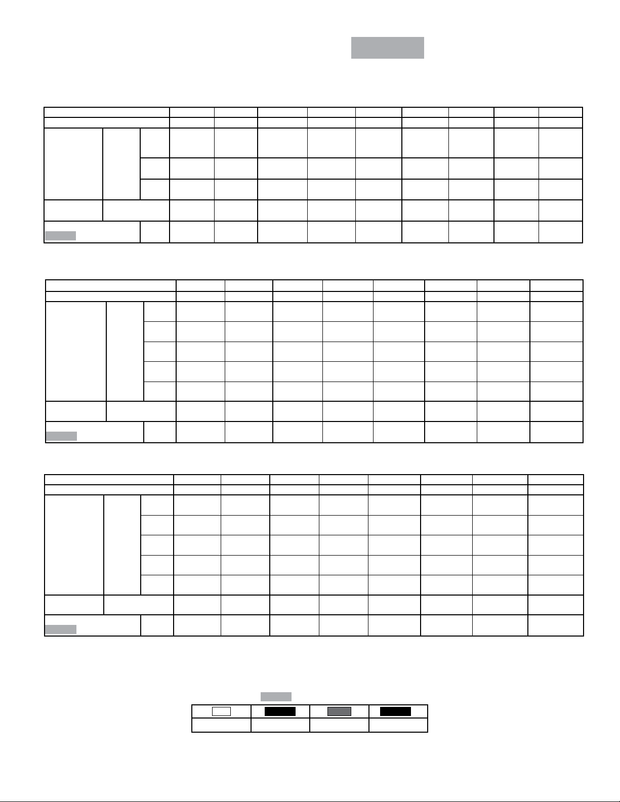
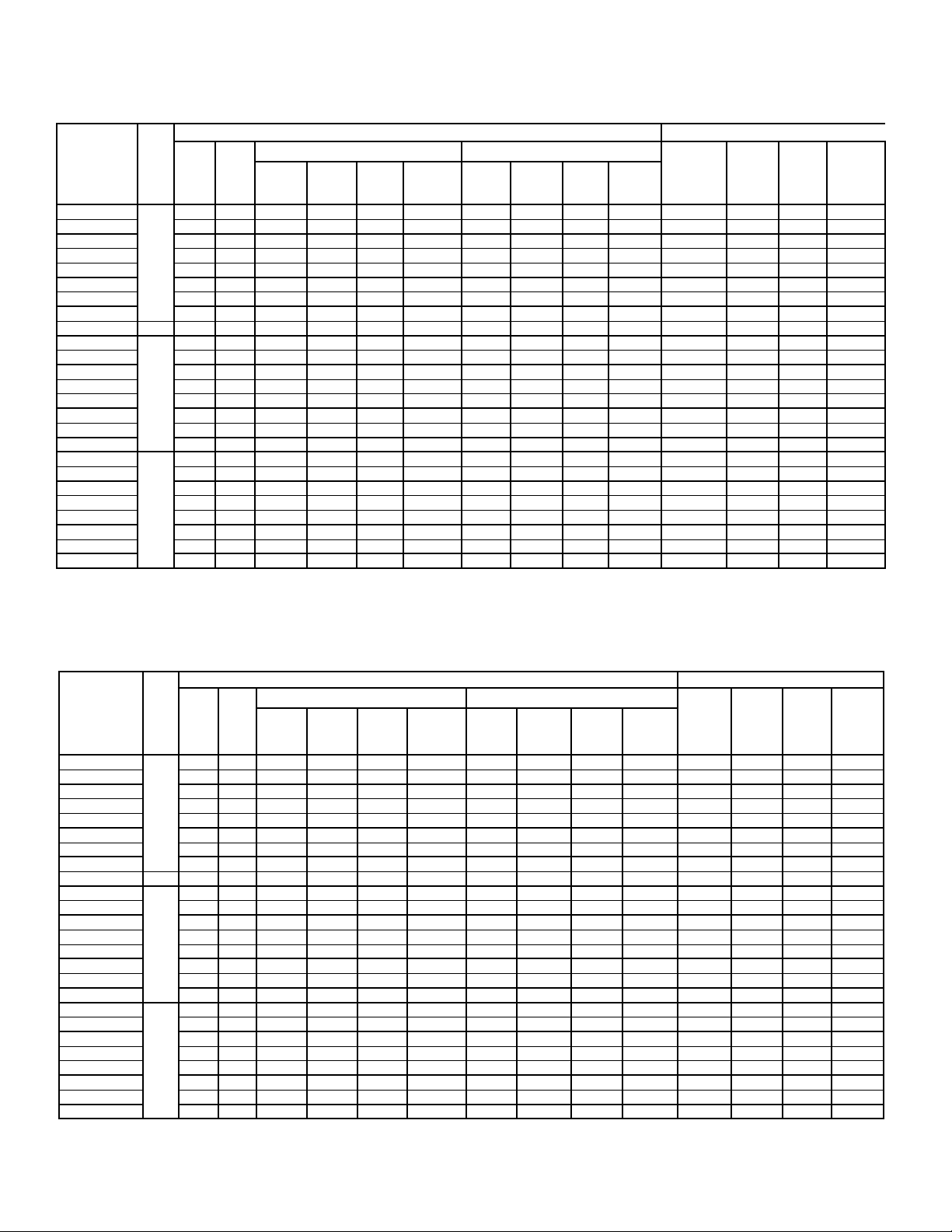
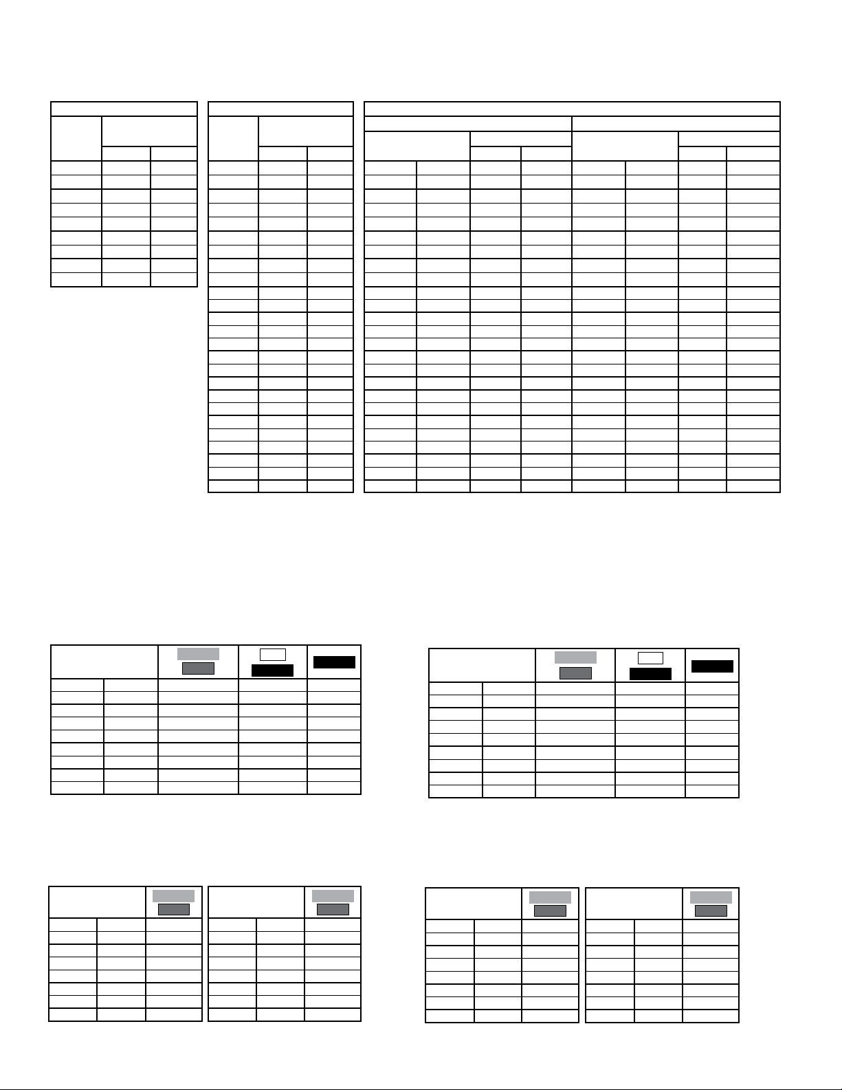
CAPACITY DATA -
B30-BMP-PDI-10
- 3 -
25/08/11
R404A
60HzBMP
ALL MODELS
Medium Temperature Models - Capacity @ 6 F.P.I. *
Medium Temp. Models 118M 122M 228M 236M 245M 355M 368M 480M 488M *
Number Of Fans 1 1 2 2 2 3 3 4 4
4.7
36000
(10500)
35640
(10445)
35280
(10340)
6870
(3240)
7.0
(3.2)
34100
(9990)
33200
(9720)
32000
(9370)
29500
(8640)
26800
(7850)
(3240)
6870
7.0
(3.2)
45000
(13200)
44550
(13057)
44100
(12925)
6480
(3060)
9.1
(4.1)
42200
(12400)
41200
(12100)
40000
(11700)
37000
(10800)
33800
(9900)
6480
(3060)
9.4
(4.2)
55000
(16100)
54450
(15958)
53900
(15797)
10300
(4860)
10
(4.7)
49300
(14400)
48800
(14300)
48000
(14100)
44900
(13200)
41600
(12200)
10300
(4860)
10
(4.7)
68000
(19900)
67320
(19730)
66640
(19531)
9720
(4590)
14
(6.3)
80000
(23400)
79200
(23212)
78400
(22978)
13000
(6140)
(7.4)
57300
(16800)
56800
(16600)
56000
(16400)
52600
(15400)
48900
(14300)
9720
(4590)
14
(6.3)
16
88000
(25800)
87120
(25533)
86240
(25275)
12200
(5760)
16
(7.4)
73200
(21400)
72300
(21200)
71000
(20800)
66300
(19400)
61300
(18000)
13000
(6140)
16
(7.4)
Capacity
BTUH (WATTS)
Air Flow CFM (L/S)
Refrigerant Charge
R404A
* “488M” models are 8 F.P.I.
Evap
Temp.
°F (°C)
LB.
(KG)
25/20
(-4/-7)
15
(-9)
10
(-12)
18000
(5270)
17820
(5223)
17640
(5170)
3430
(1620)
3.6
(1.6)
22000
(6440)
21780
(6383)
21560
(6319)
3240
(1530)
4.8
(2.2)
28000
(8200)
27720
(8124)
27440
(8042)
7260
(3430)
4.2
(1.9)
Low Temperature Models - Capacity @ 6 F.P.I.
Low Temp. Models 116L 119L 225L 232L 240L 348L 356L 471L
Number Of Fans 1 1 2 2 2 3 3 4
Capacity BTUH
(WATTS)
Air Flow CFM (L/S)
Refrigerant Charge
Evap
Temp.
°F (°C)
R404A
0
(-18)
-10
(-23)
-20
(-29)
-30
(-34)
-40
(-40)
LB.
(KG)
16500
(4830)
16300
(4770)
16000
(4690)
14900
(4360)
13800
(4040)
3430
(1620)
3.6
(1.6)
20100
(5890)
19600
(5740)
19000
(5570)
17600
(5160)
16000
(4690)
3240
(1530)
4.8
(2.2)
26400
(7730)
25700
(7530)
25000
(7320)
23100
(6770)
21100
(6180)
7260
(3430)
(2.1)
Low Temperature Models - Capacity @ 4 F.P.I.
Low Temp. 4 FPI Models 113V 117V 222V 228V 234V 339V 350V 459V
Number Of Fans 1 1 2 2 2 3 3 4
0
(-18)
-10
Capacity
BTUH (WATTS)
Air Flow CFM (L/S)
Refrigerant Charge
Evap
Temp.
°F (°C)
R404A
Capacities rated using R404A with 10°F (5.6°C) TD & 100°F (38°C) liquid temperature.
Capacities at other TD within a range of 8 to 15 °F (4.4 to 8.3°C) are directly proportional to TD, or use formula: Capacity = Rated capacity ÷ 10 x TD.
For capacities at TD outside of range 8 to 15 °F (4.4 to 8.3°C), or liquid temperature lower than 75°F (24°), consult factory.
* When using R407C, the factor above is to be used when matching to condensing units with Dew Point ratings. This factor will ensure that proper
system balancing will occur to compensate for glide to t the application. If the system is sized correctly, one may expect a slight increase in system
capacity, along with slightly higher saturated suction temperatures.
(-23)
-20
(-29)
-30
(-34)
-40
(-40)
LB.
(KG)
13300
(3900)
13200
(3870)
13000
(3800)
12200
(3570)
11400
(3340)
3640
(1720)
3.6
(1.6)
17700
(5190)
17400
(5100)
17000
(4980)
15800
(4630)
14600
(4280)
3430
(1620)
4.8
(2.2)
22800
(6680)
22500
(6590)
22000
(6440)
20500
(6000)
18900
(5540)
7690
(3630)
4.7
(2.1)
29300
(8580)
28700
(8410)
28000
(8200)
26000
(7620)
23900
(7000)
7280
(3440)
7.0
(3.2)
Correction Factors for Other Refrigerants
R404A
Use
R22
0.95 0.90 1.00 0.90
Values Multiplied By:
R134a
R507
35300
(10300)
34700
(10200)
34000
(9960)
31700
(9290)
29200
(8550)
6870
(3240)
9.4
(4.2)
R407C
43700
(12800)
41700
(12200)
39000
(11400)
35700
(10500)
31700
(9290)
10900
(5140)
10
(4.7)
*
55000
(16100)
52900
(15500)
50000
(14700)
45900
(13400)
41000
(12000)
10300
(4860)
14
(6.3)
60300
(17700)
59800
(17500)
59000
(17300)
55500
(16300)
51600
(15100)
13700
(6470)
16
(7.4)
Page 4
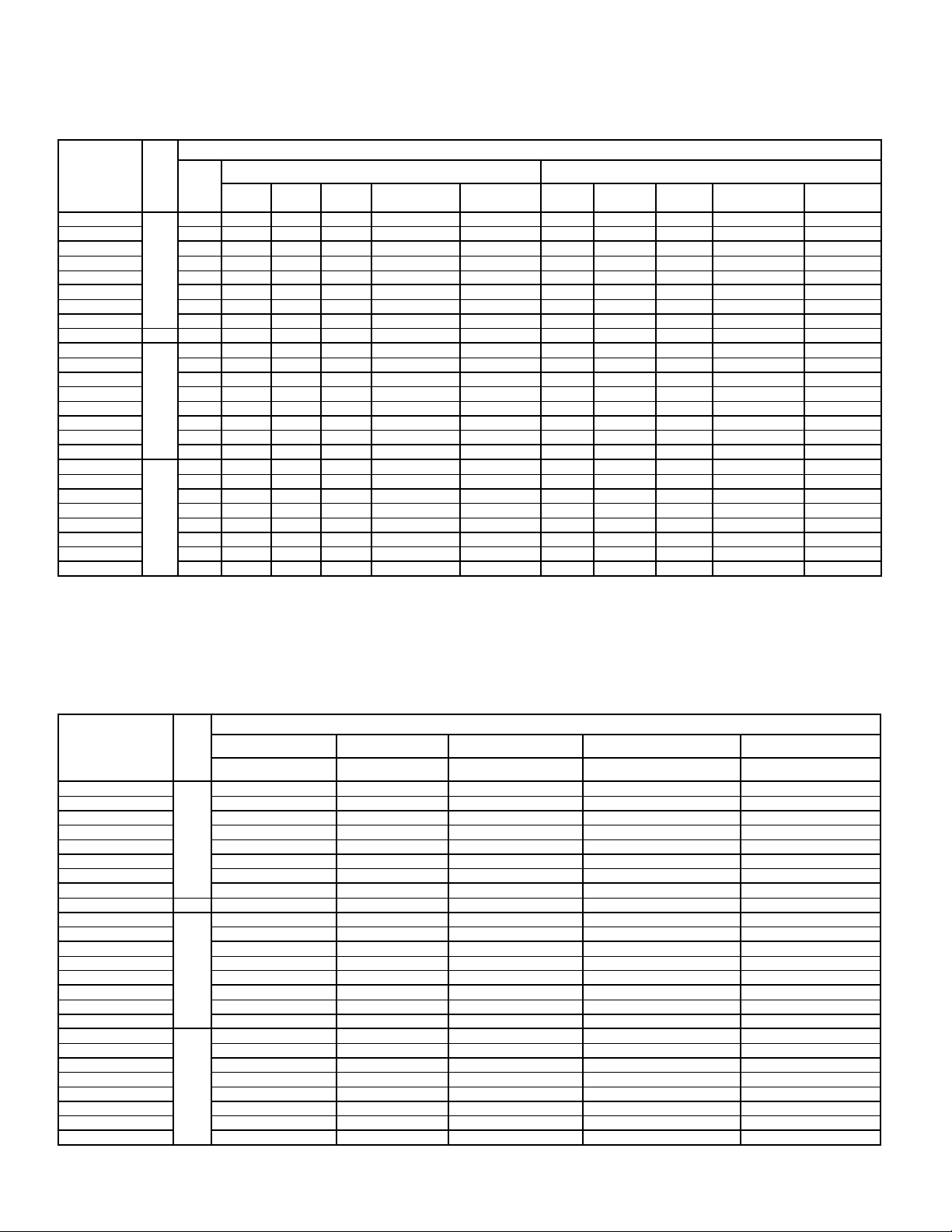
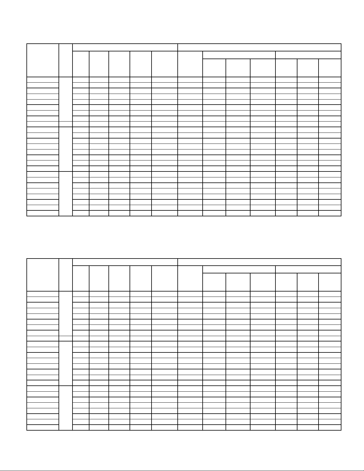
ELECTRICAL DATA - 208-230/1/60
B30-BMP-PDI-10
- 4 -
25/08/11
AIR DEFROST & HOT GAS DEFROST
60HzBMP
WITH HOT GAS LOOP PAN MODELS
FAN MOTORS
MODEL FPI
118M#-S2A
122M#-S2A 1 1/3 1.7 320 2.1 15 1/3 2.6 245 3.3 15
228M#-S2A 2 1/3 3.4 640 3.8 15 1/3 5.2 490 5.9 15
236M#-S2A 2 1/3 3.4 640 3.8 15 1/3 5.2 490 5.9 15
245M#-S2A 2 1/3 3.4 640 3.8 15 1/3 5.2 490 5.9 15
355M#-S2A 3 1/3 5.1 960 5.5 15 1/3 7.8 735 8.5 15
368M#-S2A 3 1/3 5.1 960 5.5 15 1/3 7.8 735 8.5 15
480M#-S2A 4 1/3 6.8 1280 7.2 15 1/3 10.4 980 11.1 15
488M#-S2A 8 4 1/3 6.8 1280 7.2 15 1/3 10.4 980 11.1 15
116L†-S2A
119L†-S2A 1 1/3 1.7 320 2.1 15 1/3 2.6 245 3.3 15
225L#-S2A 2 1/3 3.4 640 3.8 15 1/3 5.2 490 5.9 15
232L#-S2A 2 1/3 3.4 640 3.8 15 1/3 5.2 490 5.9 15
240L#-S2A 2 1/3 3.4 640 3.8 15 1/3 5.2 490 5.9 15
348L#-S2A 3 1/3 5.1 960 5.5 15 1/3 7.8 735 8.5 15
356L#-S2A 3 1/3 5.1 960 5.5 15 1/3 7.8 735 8.5 15
471L#-S2A 4 1/3 6.8 1280 7.2 15 1/3 10.4 735 11.1 15
113V†-S2A
117V†-S2A 1 1/3 1.7 320 2.1 15 1/3 2.6 245 3.3 15
222V#-S2A 2 1/3 3.4 640 3.8 15 1/3 5.2 490 5.9 15
228V#-S2A 2 1/3 3.4 640 3.8 15 1/3 5.2 490 5.9 15
234V#-S2A 2 1/3 3.4 640 3.8 15 1/3 5.2 490 5.9 15
339V#-S2A 3 1/3 5.1 960 5.5 15 1/3 7.8 735 8.5 15
350V#-S2A 3 1/3 5.1 960 5.5 15 1/3 7.8 735 8.5 15
459V#-S2A 4 1/3 6.8 1280 7.2 15 1/3 10.4 980 11.1 15
# = A, H or R. Refer to Nomenclature for details † = H or R. Refer to Nomenclature for details
QTY
6
6
4
HP
1 1/3 1.7 320 2.1 15 1/3 2.6 245 3.3 15
1 1/3 1.7 320 2.1 15 1/3 2.6 245 3.3 15
1 1/3 1.7 320 2.1 15 1/3 2.6 245 3.3 15
STANDARD PSC MOTORS OPTIONAL EC MOTORS
FLA
TOTAL
WATTS
MIN. CIRC.
AMPACITY (A)
MAX. FUSE
(AMPS)
HP
FLA
TOTAL
WATTS
MIN. CIRC.
AMPACITY (A)
MAX. FUSE
(AMPS)
ELECTRICAL DATA - 460/1/60
AIR DEFROST & HOT GAS DEFROST
WITH HOT GAS LOOP PAN MODELS
FAN MOTORS
MODEL FPI
QUANTITY HP FLA TOTAL MIN. CIRC. AMPACITY (A) MAX. FUSE (AMPS)
118M#-S4A
122M#-S4A 1 1/3 0.9 1.1 15
228M#-S4A 2 1/3 1.8 2.0 15
236M#-S4A 2 1/3 1.8 2.0 15
245M#-S4A 2 1/3 1.8 2.0 15
355M#-S4A 3 1/3 2.7 2.9 15
368M#-S4A 3 1/3 2.7 2.9 15
480M#-S4A 4 1/3 3.6 3.8 15
488M#-S4A 8 4 1/3 3.6 3.8 15
116L†-S4A
119L†-S4A 1 1/3 0.9 1.1 15
225L#-S4A 2 1/3 1.8 2.0 15
232L#-S4A 2 1/3 1.8 2.0 15
240L#-S4A 2 1/3 1.8 2.0 15
348L#-S4A 3 1/3 2.7 2.9 15
356L#-S4A 3 1/3 2.7 2.9 15
471L#-S4A 4 1/3 3.6 3.8 15
113V†S4A
117V†S4A 1 1/3 0.9 1.1 15
222V#-S4A 2 1/3 1.8 2.0 15
228V#-S4A 2 1/3 1.8 2.0 15
234V#-S4A 2 1/3 1.8 2.0 15
339V#-S4A 3 1/3 2.7 2.9 15
350V#-S4A 3 1/3 2.7 2.9 15
459V#-S4A 4 1/3 3.6 3.8 15
# = A, H or R. Refer to Nomenclature for details † = H or R. Refer to Nomenclature for details
6
6
4
1 1/3 0.9 1.1 15
1 1/3 0.9 1.1 15
1 1/3 0.9 1.1 15
Page 5
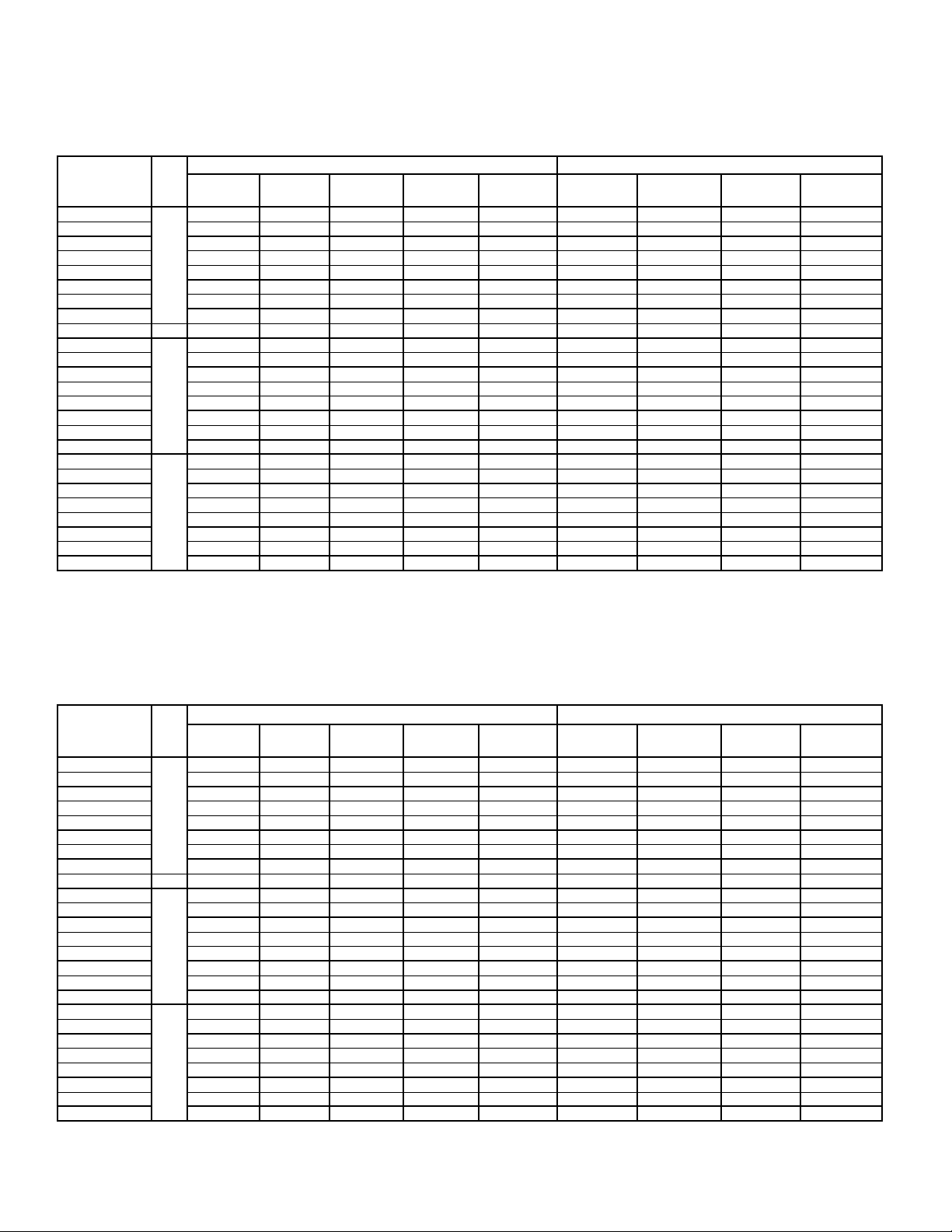
ELECTRICAL DATA - 575/1/60
B30-BMP-PDI-10
- 5 -
25/08/11
AIR DEFROST & HOT GAS DEFROST
WITH HOT GAS LOOP PAN MODELS
MODEL FPI
118M#-S5A
122M#-S5A 1 1/3 0.7 0.9 15
228M#-S5A 2 1/3 1.4 1.6 15
236M#-S5A 2 1/3 1.4 1.6 15
245M#-S5A 2 1/3 1.4 1.6 15
355M#-S5A 3 1/3 2.1 2.3 15
368M#-S5A 3 1/3 2.1 2.3 15
480M#-S5A 4 1/3 2.8 3.0 15
488M#-S5A 8 4 1/3 2.8 3.0 15
116L†-S5A
119L†-S5A 1 1/3 0.7 0.9 15
225L#-S5A 2 1/3 1.4 1.6 15
232L#-S5A 2 1/3 1.4 1.6 15
240L#-S5A 2 1/3 1.4 1.6 15
348L#-S5A 3 1/3 2.1 2.3 15
356L#-S5A 3 1/3 2.1 2.3 15
471L#-S5A 4 1/3 2.8 3.0 15
113V†-S5A
117V†-S5A 1 1/3 0.7 0.9 15
222V#-S5A 2 1/3 1.4 1.6 15
228V#-S5A 2 1/3 1.4 1.6 15
234V#-S5A 2 1/3 1.4 1.6 15
339V#-S5A 3 1/3 2.1 2.3 15
350V#-S5A 3 1/3 2.1 2.3 15
459V#-S5A 4 1/3 2.8 3.0 15
# = A, H or R. Refer to Nomenclature for details
† = H or R. Refer to Nomenclature for details
6
6
4
QUANTITY HP FLA TOTAL MIN. CIRC. AMPACITY (A) MAX. FUSE (AMPS)
1 1/3 0.7 0.9 15
1 1/3 0.7 0.9 15
1 1/3 0.7 0.9 15
FAN MOTORS
60HzBMP
Page 6
ELECTRICAL DATA - 208-230/1/60
B30-BMP-PDI-10
- 6 -
25/08/11
TOTAL
AMPS
60HzBMP
MCA
(A)
ELECTRIC DEFROST MODELS
FAN MOTORS DEFROST HEATERS
MODEL FPI
118ME-*A
122ME-*A 1 1/3 1.7 320 2.1 15 2.6 245 3.3 15 3330 14.5 18 20
228ME-*A 2 1/3 3.4 640 3.8 15 5.2 490 5.9 15 6190 26.9 34 35
236ME-*A 2 1/3 3.4 640 3.8 15 5.2 490 5.9 15 6190 26.9 34 35
245ME-*A 2 1/3 3.4 640 3.8 15 5.2 490 5.9 15 6190 26.9 34 35
355ME-*A 3 1/3 5.1 960 5.5 15 7.8 735 8.5 15 9040 39.3 49 50
368ME-*A 3 1/3 5.1 960 5.5 15 7.8 735 8.5 15 9040 39.3 49 50
480ME-*A 4 1/3 6.8 1280 7.2 15 10.4 980 11.1 15 10600 46.1 58 60
488ME-*A 8 4 1/3 6.8 1280 7.2 15 10.4 980 11.1 15 10600 46.1 58 60
116LE-*A
119LE-*A 1 1/3 1.7 320 2.1 15 2.6 245 3.3 15 3330 14.5 18 20
225LE-*A 2 1/3 3.4 640 3.8 15 5.2 490 5.9 15 6190 26.9 34 35
232LE-*A 2 1/3 3.4 640 3.8 15 5.2 490 5.9 15 6190 26.9 34 35
240LE-*A 2 1/3 3.4 640 3.8 15 5.2 490 5.9 15 6190 26.9 34 35
348LE-*A 3 1/3 5.1 960 5.5 15 7.8 735 8.5 15 9040 39.3 49 50
356LE-*A 3 1/3 5.1 960 5.5 15 7.8 735 8.5 15 9040 39.3 49 50
471LE-*A 4 1/3 6.8 1280 7.2 15 10.4 735 11.1 15 10600 46.1 58 60
113VE-*A
117VE-*A 1 1/3 1.7 320 2.1 15 2.6 245 3.3 15 3330 14.5 18 20
222VE-*A 2 1/3 3.4 640 3.8 15 5.2 490 5.9 15 6190 26.9 34 35
228VE-*A 2 1/3 3.4 640 3.8 15 5.2 490 5.9 15 6190 26.9 34 35
234VE-*A 2 1/3 3.4 640 3.8 15 5.2 490 5.9 15 6190 26.9 34 35
339VE-*A 3 1/3 5.1 960 5.5 15 7.8 735 8.5 15 9040 39.3 49 50
350VE-*A 3 1/3 5.1 960 5.5 15 7.8 735 8.5 15 9040 39.3 49 50
459VE-*A 4 1/3
* = S2 or T3. Refer to Nomenclature for details
QTY. HP
1 1/3 1.7 320 2.1 15 2.6 245 3.3 15 3330 14.5 18 20
6
1 1/3 1.7 320 2.1 15 2.6 245 3.3 15 3330 14.5 18 20
6
1 1/3 1.7 320 2.1 15 2.6 245 3.3 15 3330 14.5 18 20
4
STANDARD PSC MOTORS OPTIONAL EC MOTORS
FLA
TOTAL
WATTS
6.8 1280 7.2 15 10.4 980 11.1
MCA
(A)
MAX.
FUSE
(AMPS)
FLA
TOTAL
WATTS
MCA
(A)
MAX.
FUSE
(AMPS)
15 10600 46.1 58 60
TOTAL
WATTS
MAX.
FUSE
(AMPS)
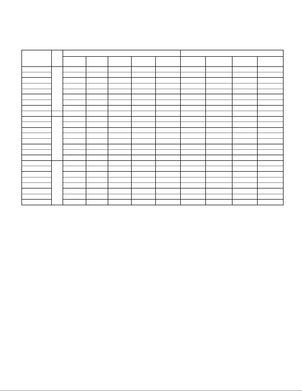
ELECTRICAL DATA - 208-230/3/60
ELECTRIC DEFROST MODELS
FAN MOTORS DEFROST HEATERS
MODEL FPI
118ME-*A
122ME-*A 1 1/3 1.7 320 2.1 15 2.6 245 3.3 15 3330 9.9 12 15
228ME-*A 2 1/3 3.4 640 3.8 15 5.2 490 5.9 15 6190 18.3 23 25
236ME-*A 2 1/3 3.4 640 3.8 15 5.2 490 5.9 15 6190 18.3 23 25
245ME-*A 2 1/3 3.4 640 3.8 15 5.2 490 5.9 15 6190 18.3 23 25
355ME-*A 3 1/3 5.1 960 5.5 15 7.8 735 8.5 15 9040 26.7 33 35
368ME-*A 3 1/3 5.1 960 5.5 15 7.8 735 8.5 15 9040 26.7 33 35
480ME-*A 4 1/3 6.8 1280 7.2 15 10.4 980 11.1 15 10600 31.2 39 40
488ME-*A 8 4 1/3 6.8 1280 7.2 15 10.4 980 11.1 15 10600 31.2 39 40
116LE-*A
119LE-*A 1 1/3 1.7 320 2.1 15 2.6 245 3.3 15 3330 9.9 12 15
225LE-*A 2 1/3 3.4 640 3.8 15 5.2 490 5.9 15 6190 18.3 23 25
232LE-*A 2 1/3 3.4 640 3.8 15 5.2 490 5.9 15 6190 18.3 23 25
240LE-*A 2 1/3 3.4 640 3.8 15 5.2 490 5.9 15 6190 18.3 23 25
348LE-*A 3 1/3 5.1 960 5.5 15 7.8 735 8.5 15 9040 26.7 33 35
356LE-*A 3 1/3 5.1 960 5.5 15 7.8 735 8.5 15 9040 26.7 33 35
471LE-*A 4 1/3 6.8 1280 7.2 15 10.4 735 11.1 15 10600 31.2 39 40
113VE-*A
117VE-*A 1 1/3 1.7 320 2.1 15 2.6 245 3.3 15 3330 9.9 12 15
222VE-*A 2 1/3 3.4 640 3.8 15 5.2 490 5.9 15 6190 18.3 23 25
228VE-*A 2 1/3 3.4 640 3.8 15 5.2 490 5.9 15 6190 18.3 23 25
234VE-*A 2 1/3 3.4 640 3.8 15 5.2 490 5.9 15 6190 18.3 23 25
339VE-*A 3 1/3 5.1 960 5.5 15 7.8 735 8.5 15 9040 26.7 33 35
350VE-*A 3 1/3 5.1 960 5.5 15 7.8 735 8.5 15 9040 26.7 33 35
459VE-*A 4 1/3
* = S2 or T3. Refer to Nomenclature for details
QTY. HP
1 1/3 1.7 320 2.1 15 2.6 245 3.3 15 3330 9.9 12 15
6
1 1/3 1.7 320 2.1 15 2.6 245 3.3 15 3330 9.9 12 15
6
1 1/3 1.7 320 2.1 15 2.6 245 3.3 15 3330 9.9 12 15
4
STANDARD PSC MOTORS OPTIONAL EC MOTORS
FLA
TOTAL
WATTS
6.8 1280 7.2 15 10.4 980 11.1
MCA
(A)
MAX.
FUSE
(AMPS)
FLA
TOTAL
WATTS
MCA
(A)
MAX.
FUSE
(AMPS)
TOTAL
WATTS
15 10600 31.2 39 40
TOTAL
AMPS
MCA
(A)
MAX.
FUSE
(AMPS)
Page 7
ELECTRICAL DATA - 460/1/60 & 460/3/60
B30-BMP-PDI-10
- 7 -
25/08/11
ELECTRIC DEFROST MODELS
FAN MOTORS DEFROST HEATERS
MODEL FPI
118ME-*A
122ME-*A 1 1/3 0.9 1.1 15 3330 7.2 9.0 15 5.0 6.2 15
228ME-*A 2 1/3 1.8 2.0 15 6190 13.5 17 20 9.2 11 15
236ME-*A 2 1/3 1.8 2.0 15 6190 13.5 17 20 9.2 11 15
245ME-*A 2 1/3 1.8 2.0 15 6190 13.5 17 20 9.2 11 15
355ME-*A 3 1/3 2.7 2.9 15 9040 19.7 25 25 13.4 17 20
368ME-*A 3 1/3 2.7 2.9 15 9040 19.7 25 25 13.4 17 20
480ME-*A 4 1/3 3.6 3.8 15 10600 23.0 29 30 15.6 19 20
488ME-*A 8 4 1/3 3.6 3.8 15 10600 23.0 29 30 15.6 19 20
116LE-*A
119LE-*A 1 1/3 0.9 1.1 15 3330 7.2 9.0 15 5.0 6.2 15
225LE-*A 2 1/3 1.8 2.0 15 6190 13.5 17 20 9.2 11 15
232LE-*A 2 1/3 1.8 2.0 15 6190 13.5 17 20 9.2 11 15
240LE-*A 2 1/3 1.8 2.0 15 6190 13.5 17 20 9.2 11 15
348LE-*A 3 1/3 2.7 2.9 15 9040 19.7 25 25 13.4 17 20
356LE-*A 3 1/3 2.7 2.9 15 9040 19.7 25 25 13.4 17 20
471LE-*A 4 1/3 3.6 3.8 15 10600 23.0 29 30 15.6 19 20
113VE-*A
117VE-*A 1 1/3 0.9 1.1 15 3330 7.2 9.0 15 5.0 6.2 15
222VE-*A 2 1/3 1.8 2.0 15 6190 13.5 17 20 9.2 11 15
228VE-*A 2 1/3 1.8 2.0 15 6190 13.5 17 20 9.2 11 15
234VE-*A 2 1/3 1.8 2.0 15 6190 13.5 17 20 9.2 11 15
339VE-*A 3 1/3 2.7 2.9 15 9040 19.7 25 25 13.4 17 20
350VE-*A 3 1/3 2.7 2.9 15 9040 19.7 25 25 13.4 17 20
459VE-*A 4 1/3 3.6 3.8 15 10600 23.0 29 30 15.6 19 20
* = S4 or T4. Refer to Nomenclature for details
QTY. HP
1 1/3 0.9 1.1 15 3330 7.2 9.0 15 5.0 6.2 15
6
1 1/3 0.9 1.1 15 3330 7.2 9.0 15 5.0 6.2 15
6
1 1/3 0.9 1.1 15 3330 7.2 9.0 15 5.0 6.2 15
4
FLA
TOTAL
MCA
(A)
MAX.
FUSE
(AMPS)
TOTAL
WATTS
TOTAL
AMPS
460/1/60 460/3/60
MCA
(A)
MAX.
FUSE
(AMPS)
TOTAL
AMPS
60HzBMP
MCA
(A)
MAX.
FUSE
(AMPS)
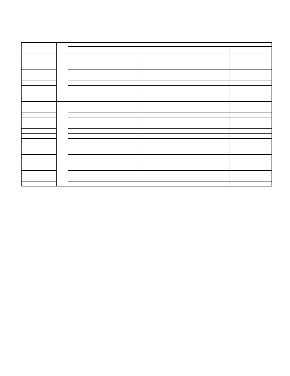
ELECTRICAL DATA - 575/1/60 & 575/3/60
ELECTRIC DEFROST MODELS
FAN MOTORS DEFROST HEATERS
MODEL FPI
118ME-*A
122ME-*A 1 1/3 0.7 0.9 15 3330 5.8 7.2 15 4.0 5.0 15
228ME-*A 2 1/3 1.4 1.6 15 6190 10.8 13 15 7.3 9.2 15
236ME-*A 2 1/3 1.4 1.6 15 6190 10.8 13 15 7.3 9.2 15
245ME-*A 2 1/3 1.4 1.6 15 6190 10.8 13 15 7.3 9.2 15
355ME-*A 3 1/3 2.1 2.3 15 9040 15.7 20 20 10.7 13 15
368ME-*A 3 1/3 2.1 2.3 15 9040 15.7 20 20 10.7 13 15
480ME-*A 4 1/3 2.8 3.0 15 10600 18.4 23 25 12.5 16 20
488ME-*A 8 4 1/3 2.8 3.0 15 10600 18.4 23 25 12.5 16 20
116LE-*A
119LE-*A 1 1/3 0.7 0.9 15 3330 5.8 7.2 15 4.0 5.0 15
225LE-*A 2 1/3 1.4 1.6 15 6190 10.8 13 15 7.3 9.2 15
232LE-*A 2 1/3 1.4 1.6 15 6190 10.8 13 15 7.3 9.2 15
240LE-*A 2 1/3 1.4 1.6 15 6190 10.8 13 15 7.3 9.2 15
348LE-*A 3 1/3 2.1 2.3 15 9040 15.7 20 20 10.7 13 15
356LE-*A 3 1/3 2.1 2.3 15 9040 15.7 20 20 10.7 13 15
471LE-*A 4 1/3 2.8 3.0 15 10600 18.4 23 25 12.5 16 20
113VE-*A
117VE-*A 1 1/3 0.7 0.9 15 3330 5.8 7.2 15 4.0 5.0 15
222VE-*A 2 1/3 1.4 1.6 15 6190 10.8 13 15 7.3 9.2 15
228VE-*A 2 1/3 1.4 1.6 15 6190 10.8 13 15 7.3 9.2 15
234VE-*A 2 1/3 1.4 1.6 15 6190 10.8 13 15 7.3 9.2 15
339VE-*A 3 1/3 2.1 2.3 15 9040 15.7 20 20 10.7 13 15
350VE-*A 3 1/3 2.1 2.3 15 9040 15.7 20 20 10.7 13 15
459VE-*A 4 1/3 2.8 3.0 15 10600 18.4 23 25 12.5 16 20
* = S5 or T5. Refer to Nomenclature for details
QTY. HP
1 1/3 0.7 0.9 15 3330 5.8 7.2 15 4.0 5.0 15
6
1 1/3 0.7 0.9 15 3330 5.8 7.2 15 4.0 5.0 15
6
1 1/3 0.7 0.9 15 3330 5.8 7.2 15 4.0 5.0 15
4
FLA
TOTAL
MCA
(A)
MAX.
FUSE
(AMPS)
TOTAL
WATTS
TOTAL
AMPS
575/1/60 575/3/60
MCA
(A)
MAX.
FUSE
(AMPS)
TOTAL
AMPS
MCA
(A)
MAX.
FUSE
(AMPS)
Page 8
ELECTRICAL DATA - 208-230/1/60
B30-BMP-PDI-10
- 8 -
25/08/11
HOT GAS DEFROST
60HzBMP
WITH DRAIN PAN HEATER MODELS
FAN MOTORS DRAIN PAN HEATERS
MODEL FPI
118M^-S2A
122M^-S2A 1 1/3 1.7 2.1 15 534 2.3 2.9 15
228M^-S2A 2 1/3 3.4 3.8 15 887 3.9 4.8 15
236M^-S2A 2 1/3 3.4 3.8 15 887 3.9 4.8 15
245M^-S2A 2 1/3 3.4 3.8 15 887 3.9 4.8 15
355M^-S2A 3 1/3 5.1 5.5 15 1240 5.4 6.7 15
368M^-S2A 3 1/3 5.1 5.5 15 1240 5.4 6.7 15
480M^-S2A 4 1/3 6.8 7.2 15 1430 6.0 7.8 15
488M^-S2A 8 4 1/3 6.8 7.2 15 1430 6.0 7.8 15
116L^-S2A
119L^-S2A 1 1/3 1.7 2.1 15 534 2.3 2.9 15
225L^-S2A 2 1/3 3.4 3.8 15 887 3.9 4.8 15
232L^-S2A 2 1/3 3.4 3.8 15 887 3.9 4.8 15
240L^-S2A 2 1/3 3.4 3.8 15 887 3.9 4.8 15
348L^-S2A 3 1/3 5.1 5.5 15 1240 5.4 6.7 15
356L^-S2A 3 1/3 5.1 5.5 15 1240 5.4 6.7 15
471L^-S2A 4 1/3 6.8 7.2 15 1430 6.2 7.8 15
113V^-S2A
117V^-S2A 1 1/3 1.7 2.1 15 534 2.3 2.9 15
222V^-S2A 2 1/3 3.4 3.8 15 887 3.9 4.8 15
228V^-S2A 2 1/3 3.4 3.8 15 887 3.9 4.8 15
234V^-S2A 2 1/3 3.4 3.8 15 887 3.9 4.8 15
339V^-S2A 3 1/3 5.1 5.5 15 1240 5.4 6.7 15
350V^-S2A 3 1/3 5.1 5.5 15 1240 5.4 6.7 15
459V^-S2A 4 1/3 6.8 7.2 15 1430 6.2 7.8 15
^ = T or G. Refer to Nomenclature for details
QTY. HP
1 1/3 1.7 2.1 15 534 2.3 2.9 15
6
1 1/3 1.7 2.1 15 534 2.3 2.9 15
6
1 1/3 1.7 2.1 15 534 2.3 2.9 15
4
FLA
TOTAL
MCA
(A)
MAX. FUSE
(AMPS)
TOTAL
WATTS
TOTAL AMPS
MCA
(A)
MAX. FUSE
(AMPS)
ELECTRICAL DATA - 460/1/60
HOT GAS DEFROST
WITH DRAIN PAN HEATER MODELS
FAN MOTORS DRAIN PAN HEATERS
MODEL FPI
118M^-S4A
122M^-S4A 1 1/3 0.9 1.1 15 534 1.2 1.5 15
228M^-S4A 2 1/3 1.8 2.0 15 887 1.9 2.4 15
236M^-S4A 2 1/3 1.8 2.0 15 887 1.9 2.4 15
245M^-S4A 2 1/3 1.8 2.0 15 887 1.9 2.4 15
355M^-S4A 3 1/3 2.7 2.9 15 1240 2.7 3.4 15
368M^-S4A 3 1/3 2.7 2.9 15 1240 2.7 3.4 15
480M^-S4A 4 1/3 3.6 3.8 15 1430 3.1 3.9 15
488M^-S4A 8 4 1/3 3.6 3.8 15 1430 3.1 3.9 15
116L^-S4A
119L^-S4A 1 1/3 0.9 1.1 15 534 1.2 1.5 15
225L^-S4A 2 1/3 1.8 2.0 15 887 1.9 2.4 15
232L^-S4A 2 1/3 1.8 2.0 15 887 1.9 2.4 15
240L^-S4A 2 1/3 1.8 2.0 15 887 1.9 2.4 15
348L^-S4A 3 1/3 2.7 2.9 15 1240 2.7 3.4 15
356L^-S4A 3 1/3 2.7 2.9 15 1240 2.7 3.4 15
471L^-S4A 4 1/3 3.6 3.8 15 1430 3.1 3.9 15
113V^-S4A
117V^-S4A 1 1/3 0.9 1.1 15 534 1.2 1.5 15
222V^-S4A 2 1/3 1.8 2.0 15 887 1.9 2.4 15
228V^-S4A 2 1/3 1.8 2.0 15 887 1.9 2.4 15
234V^-S4A 2 1/3 1.8 2.0 15 887 1.9 2.4 15
339V^-S4A 3 1/3 2.7 2.9 15 1240 2.7 3.4 15
350V^-S4A 3 1/3 2.7 2.9 15 1240 2.7 3.4 15
459V^-S4A 4 1/3 3.6 3.8 15 1430 3.1 3.9 15
^ = T or G. Refer to Nomenclature for details
QTY. HP
1 1/3 0.9 1.1 15 534 1.2 1.5 15
6
1 1/3 0.9 1.1 15 534 1.2 1.5 15
6
1 1/3 0.9 1.1 15 534 1.2 1.5 15
4
FLA
TOTAL
MCA
(A)
MAX. FUSE
(AMPS)
TOTAL
WATTS
TOTAL AMPS
MCA
(A)
MAX. FUSE
(AMPS)
Page 9
ELECTRICAL DATA - 575/1/60
B30-BMP-PDI-10
- 9 -
25/08/11
HOT GAS DEFROST
60HzBMP
WITH DRAIN PAN HEATER MODELS
FAN MOTORS DRAIN PAN HEATERS
MODEL FPI
118M^-S5A
122M^-S5A 1 1/3 0.7 0.9 15 534 0.9 1.2 15
228M^-S5A 2 1/3 1.4 1.6 15 887 1.5 1.9 15
236M^-S5A 2 1/3 1.4 1.6 15 887 1.5 1.9 15
245M^-S5A 2 1/3 1.4 1.6 15 887 1.5 1.9 15
355M^-S5A 3 1/3 2.1 2.3 15 1240 2.2 2.7 15
368M^-S5A 3 1/3 2.1 2.3 15 1240 2.2 2.7 15
480M^-S5A 4 1/3 2.8 3.0 15 1430 2.5 3.1 15
488M^-S5A 8 4 1/3 2.8 3.0 15 1430 2.5 3.1 15
116L^-S5A
119L^-S5A 1 1/3 0.7 0.9 15 534 0.9 1.2 15
225L^-S5A 2 1/3 1.4 1.6 15 887 1.5 1.9 15
232L^-S5A 2 1/3 1.4 1.6 15 887 1.5 1.9 15
240L^-S5A 2 1/3 1.4 1.6 15 887 1.5 1.9 15
348L^-S5A 3 1/3 2.1 2.3 15 1240 2.2 2.7 15
356L^-S5A 3 1/3 2.1 2.3 15 1240 2.2 2.7 15
471L^-S5A 4 1/3 2.8 3.0 15 1430 2.5 3.1 15
113V^-S5A
117V^-S5A 1 1/3 0.7 0.9 15 534 0.9 1.2 15
222V^-S5A 2 1/3 1.4 1.6 15 887 1.5 1.9 15
228V^-S5A 2 1/3 1.4 1.6 15 887 1.5 1.9 15
234V^-S5A 2 1/3 1.4 1.6 15 887 1.5 1.9 15
339V^-S5A 3 1/3 2.1 2.3 15 1240 2.2 2.7 15
350V^-S5A 3 1/3 2.1 2.3 15 1240 2.2 2.7 15
459V^-S5A 4 1/3 2.8 3.0 15 1430 2.5 3.1 15
^ = T or G. Refer to Nomenclature for details
QTY. HP
1 1/3 0.7 0.9 15 534 0.9 1.2 15
6
1 1/3 0.7 0.9 15 534 0.9 1.2 15
6
1 1/3 0.7 0.9 15 534 0.9 1.2 15
4
FLA
TOTAL
MCA
(A)
MAX. FUSE
(AMPS)
TOTAL
WATTS
TOTAL AMPS
MCA
(A)
MAX. FUSE
(AMPS)
Page 10
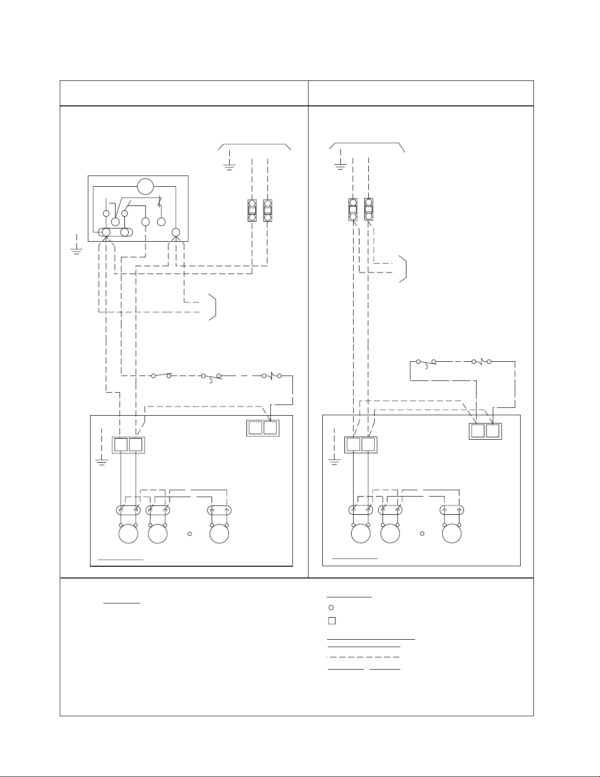
WIRING DIAGRAM - 208-230/1/60
CONDUCTORS/WIRING
AND NATIONAL CODES.
-TERMINAL BLOCK TERMINAL
ALL FIELD WIRING MUST BE DONE IN
COMPLIANCE WITH ALL APPLICABLE LOCAL
-COMPONENT TERMINAL
4). MAY BE FACTORY INSTALLED-MOUNTED AND
3). OVERCURRENT PROTECTION FOR
1). USE COPPER CONDUCTORS ONLY
VALUE SHOWN ON EVAPORATOR NAMEPLATE.
HEATERS MUST NOT EXCEED MAXIMUM
EVAPORATOR FAN MOTORS AND DEFROST
2). USE 90°C WIRE (OR HIGHER)
WIRED ON EVAPORATOR .
NOTES
TERMINALS
OPTIONAL FACTORY OR
1-MP AIR 230V 11/05
BY OTHERS
WIRING BY OTHERS
FACTORY WIRING
WITHOUT DEFROST TIME CLOCK
REQUIREMENTS
REFER TO EVAPORATOR
NAMEPLATE FOR ELECTRICAL
L1
PARAGON # 8145
DEFROST CLOCK
OR EQUIVALENT
THERMOSTAT
CIRCUIT
FUSE OR
NOTE #3
BREAKER
SWITCH
PUMP DOWN
(IF USED)
NOTE #4
SPACE
LIQUID LINE
SOLENOID VALVE
NOTE #4
N.C.
WITH DEFROST TIME CLOCK
GND
L1
GND
BREAKER
NOTE #3
FUSE OR
CIRCUIT
L2
1
TM
3
2
4 X
N
REFER TO
EVAPORATOR
DATA PLATE
FOR MOTOR
QUANTITY
GND.
FAN
MTR
FAN
MTR
FAN
MTR
EVAPORATOR
TERMINAL BOARD
FAN MOTOR
POWER
PLUGS
FAN
MTR
FAN
MTR
FAN
MTR
M2
GND.
M1
TERMINAL BOARD
REFER TO
EVAPORATOR
DATA PLATE
FOR MOTOR
QUANTITY
FAN MOTOR
POWER
PLUGS
EVAPORATOR
L2
M2
M1
TO MULTIPLE EVAPS
(IF APPLIC)
EVAPORATORS (IF APPLIC)
TO MULTIPLE
GND
M1
M2
M1
M2
NOTE #4
SPACE
THERMOSTAT
4
N
N.C.
NOTE #4
LIQUID LINE
SOLENOID VALVE
4
N
REQUIREMENTS
REFER TO EVAPORATOR
NAMEPLATE FOR ELECTRICAL
B30-BMP-PDI-10
- 10 -
25/08/11
AIR DEFROST MODELS
60HzBMP
Page 11
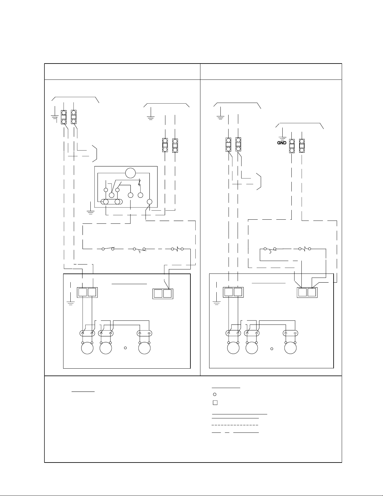
WIRING DIAGRAM -
CONDUCTORS/WIRING
AND NATIONAL CODES.
-TERMINAL BLOCK TERMINAL
ALL FIELD WIRING MUST BE DONE IN
COMPLIANCE WITH ALL APPLICABLE LOCAL
-COMPONENT TERMINAL
4). MAY BE FACTORY INSTALLED-MOUNTED AND
3). OVERCURRENT PROTECTION FOR
1). USE COPPER CONDUCTORS ONLY
VALUE SHOWN ON EVAPORATOR NAMEPLATE.
HEATERS MUST NOT EXCEED MAXIMUM
EVAPORATOR FAN MOTORS AND DEFROST
2). USE 90°C WIRE (OR HIGHER)
WIRED ON EVAPORATOR .
NOTES
TERMINALS
OPTIONAL FACTORY OR
2-MP AIR 460-575 10/05
BY OTHERS
WIRING BY OTHERS
FACTORY WIRING
WITHOUT DEFROST TIME CLOCK
REQUIREMENTS
REFER TO EVAPORATOR
NAMEPLATE FOR ELECTRICAL
L1
THERMOSTAT
CIRCUIT
FUSE OR
NOTE #3
BREAKER
SWITCH
PUMP DOWN
(IF USED)
NOTE #4
SPACE
LIQUID LINE
SOLENOID VALVE
NOTE #4
N.C.
WITH DEFROST TIME CLOCK
GND
GND
SOLENOID VALVE
THERMOSTAT
BREAKER
NOTE #3
FUSE OR
CIRCUIT
SPACE
NOTE #4
LIQUID LINE
NOTE #4
N.C.
L2
1
TM
3
2
4 X
N
REFER TO
EVAPORATOR
DATA PLATE
FOR MOTOR
QUANTITY
GND.
FAN
MTR
FAN
MTR
FAN
MTR
EVAPORATOR
TERMINAL BOARD
FAN MOTOR
POWER
PLUGS
FAN
MTR
FAN
MTR
FAN
MTR
M2
GND.
M1
TERMINAL BOARD
REFER TO
EVAPORATOR
DATA PLATE
FOR MOTOR
QUANTITY
FAN MOTOR
POWER
PLUGS
EVAPORATOR
(IF APPLIC)
TO MULTIPLE
GND
M1
M2
M1
M2
4
N
4
N
L1
L2(N)
BREAKER
NOTE #3
CIRCUIT
FUSE OR
EVAPORATORS
CONTROL VOLTAGE
2ND FUSE
OMITTED IF N
L1
L2(N)
2ND FUSE
OMITTED IF N
NAMEPLATE FOR ELECTRICAL
REFER TO EVAPORATOR
BREAKER
NOTE #3
CIRCUIT
FUSE OR
REQUIREMENTS
GND
L1
L2
CONTROL VOLTAGE
M2
M1
TO MULTIPLE
EVAPORATORS
(IF APPLIC)
B30-BMP-PDI-10
- 11 -
25/08/11
460/1/60, 575/1/60
AIR DEFROST MODELS
60HzBMP
Page 12
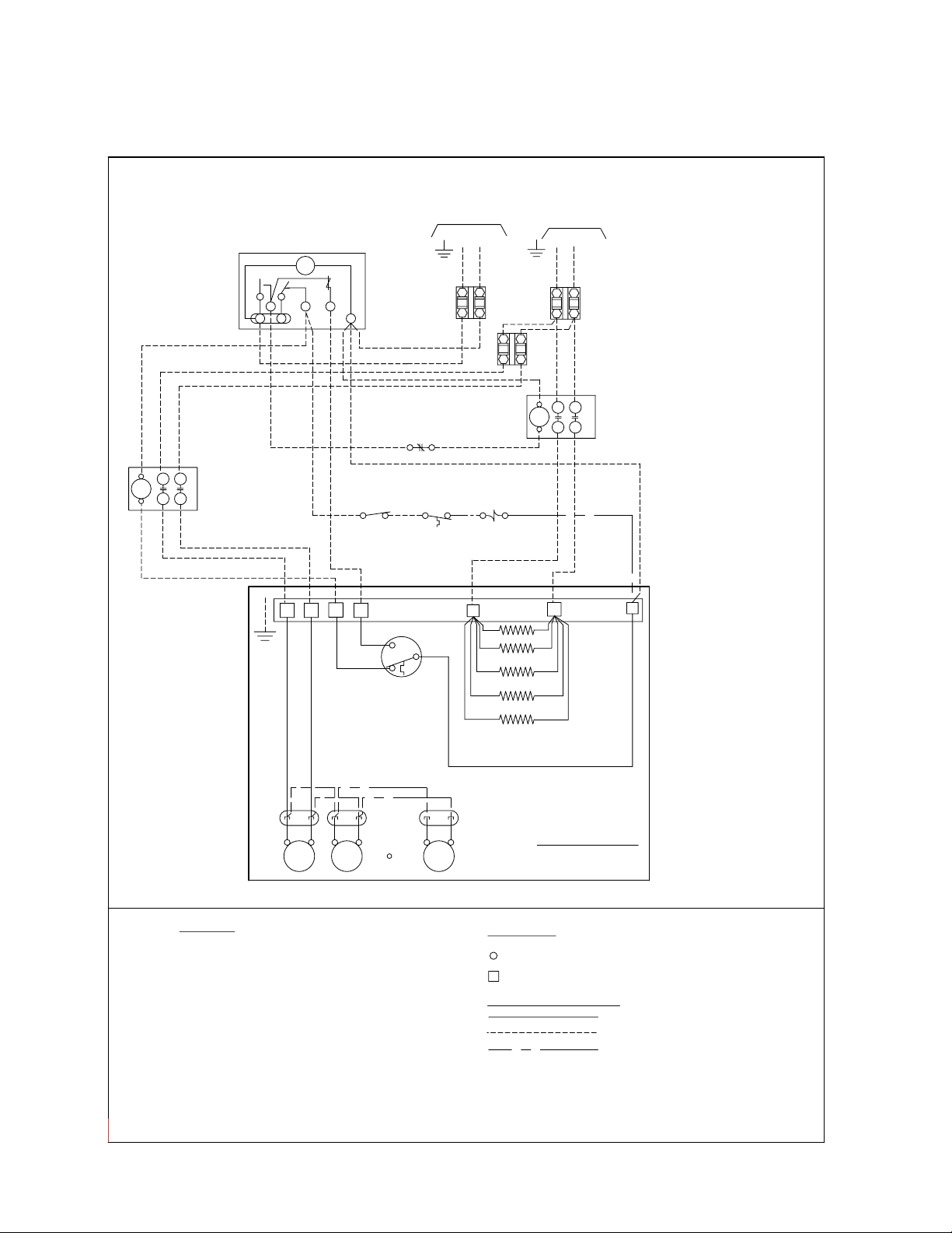
WIRING DIAGRAM -
REFER TO EVAPORATOR
NAMEPLATE FOR ELECTRICAL
REQUIREMENTS
COMPR INTERLOCK
FOR ALL MODELS USING DEFROST HEATER CONTACTOR AND FAN CONTACTOR
THERMOSTAT
NOTE #4
EVAPORATOR FAN MOTORS AND
DEFROST HEATERS MUST NOT EXCEED
1). USE COPPER CONDUCTORS ONLY
3). OVERCURRENT PROTECTION FOR
MAXIMUM VALUE SHOWN ON
EVAPORATOR NAMEPLATE.
NOTES
2). USE 90°C WIRE (OR HIGHER)
MTR
FANFAN
MTR
FAN
MTR
KLIXON DEFROST TERMINATION
CONTROL
(10.0A MAX.)
& FAN DELAY
FD-FAN DELAY
DT-DEFROST TERM
X
M2
M1
BK
GND.
C
FD
DT
BN
RD
(IF USED)
SWITCH
OR EQUIVALENT
PUMP DOWN
SPACE
(IF USED)
BREAKER
21
N
NOTE #3
TM
4 X
3
CIRCUIT
FUSE OR
DEFROST CLOCK
PARAGON # 8145
EVAPORATOR
OPTIONAL FACTORY
FACTORY WIRING
WIRING BY OTHERS
ALL FIELD WIRING MUST BE DONE IN
COMPLIANCE WITH ALL APPLICABLE LOCAL
AND NATIONAL CODES.
4A-MP ED 1 ph. ALL SINGLE 11/05
-TERMINAL BLOCK TERMINAL
-COMPONENT TERMINAL
CONDUCTORS/WIRING
TERMINALS
DATA PLATE FOR
MOTOR QUANTITY
EVAPORATOR
REFER TO
POWER PLUGS
FAN MOTOR
NOTE #4
SOL VALVE
N
L2
L1
N.C.
LIQUID LINE
GND
OR BY OTHERS
AND WIRED ON EVAPORATOR
4.) MAY BE FACTORY INSTALLED-MOUNTED
CIRCUIT
BREAKER
NOTE #3
FUSE OR
GND
L2(N)
L1
EVAP FAN
C
CONTACTOR
T2
T1
L2
L1
4
DEFROST HEATER
C
CONTACTOR
T2
T1
L2
L1
DEFROST HEATERS
H1
H2
CONTROL VOLTAGE
B30-BMP-PDI-10
- 12 -
25/08/11
208-230/1/60, 460/1/60, 575/1/60
60HzBMP
ELECTRIC DEFROST MODELS -SINGLE EVAPORATOR
Page 13

WIRING DIAGRAM - 208-230/3/60
REFER TO EVAPORATOR
NAMEPLATE FOR ELECTRICAL
REQUIREMENTS
COMPR INTERLOCK
FOR ALL MODELS USING THREE PHASE DEFROST HEATER CONTACTOR
THERMOSTAT
NOTE #4
EVAPORATOR FAN MOTORS AND
DEFROST HEATERS MUST NOT EXCEED
1). USE COPPER CONDUCTORS ONLY
3). OVERCURRENT PROTECTION FOR
MAXIMUM VALUE SHOWN ON
EVAPORATOR NAMEPLATE.
NOTES
2). USE 90°C WIRE (OR HIGHER)
MTR
FANFAN
MTR
FAN
MTR
KLIXON DEFROST TERMINATION
CONTROL
(10.0A MAX.)
& FAN DELAY
FD-FAN DELAY
DT-DEFROST TERM
X
M2
M1
BK
GND.
C
FD
DT
BN
RD
(IF USED)
SWITCH
OR EQUIVALENT
PUMP DOWN
SPACE
(IF USED)
21
N
TM
4 X
3
DEFROST CLOCK
PARAGON # 8145
EVAPORATOR
OPTIONAL FACTORY
FACTORY WIRING
WIRING BY OTHERS
ALL FIELD WIRING MUST BE DONE IN
COMPLIANCE WITH ALL APPLICABLE LOCAL
AND NATIONAL CODES.
3-MP ED 230V single 10/05
-TERMINAL BLOCK TERMINAL
-COMPONENT TERMINAL
CONDUCTORS/WIRING
TERMINALS
DATA PLATE FOR
MOTOR QUANTITY
EVAPORATOR
REFER TO
POWER PLUGS
FAN MOTOR
H2
H1
NOTE #4
SOL VALVE
N
N.C.
LIQUID LINE
OR BY OTHERS
AND WIRED ON EVAPORATOR
4.) MAY BE FACTORY INSTALLED-MOUNTED
DEFROST HEATERS
CIRCUIT
BREAKER
NOTE #3
FUSE OR
CONTACTOR
DEFROST HEATER
T2
T1
C
L2
L1
NOTE #3
BREAKER
FUSE OR
CIRCUIT
GND
L2
L1
L3
H3
T3
L3
4
WITHOUT FAN CONTACTOR
B30-BMP-PDI-10
- 13 -
25/08/11
ELECTRIC DEFROST MODELS
WITHOUT FAN CONTACTOR
60HzBMP
Page 14

WIRING DIAGRAM -
REFER TO EVAPORATOR
NAMEPLATE FOR ELECTRICAL
REQUIREMENTS
COMPR INTERLOCK
FOR ALL MODELS USING DEFROST HEATER CONTACTOR AND FAN CONTACTOR
THERMOSTAT
NOTE #4
EVAPORATOR FAN MOTORS AND
DEFROST HEATERS MUST NOT EXCEED
1). USE COPPER CONDUCTORS ONLY
3). OVERCURRENT PROTECTION FOR
MAXIMUM VALUE SHOWN ON
EVAPORATOR NAMEPLATE.
NOTES
2). USE 90°C WIRE (OR HIGHER)
MTR
FANFAN
MTR
FAN
MTR
KLIXON DEFROST TERMINATION
CONTROL
(10.0A MAX.)
& FAN DELAY
FD-FAN DELAY
DT-DEFROST TERM
X
M2
M1
BK
GND.
C
FD
DT
BN
RD
(IF USED)
SWITCH
OR EQUIVALENT
PUMP DOWN
SPACE
(IF USED)
BREAKER
21
N
NOTE #3
TM
4 X
3
CIRCUIT
FUSE OR
DEFROST CLOCK
PARAGON # 8145
EVAPORATOR
OPTIONAL FACTORY
FACTORY WIRING
WIRING BY OTHERS
ALL FIELD WIRING MUST BE DONE IN
COMPLIANCE WITH ALL APPLICABLE LOCAL
AND NATIONAL CODES.
4-MP ED ALL SINGLE 10/05
-TERMINAL BLOCK TERMINAL
-COMPONENT TERMINAL
CONDUCTORS/WIRING
TERMINALS
DATA PLATE FOR
MOTOR QUANTITY
EVAPORATOR
REFER TO
POWER PLUGS
FAN MOTOR
NOTE #4
SOL VALVE
N
L2
L1
N.C.
LIQUID LINE
GND
OR BY OTHERS
AND WIRED ON EVAPORATOR
4.) MAY BE FACTORY INSTALLED-MOUNTED
CIRCUIT
BREAKER
NOTE #3
FUSE OR
GND
L2(N)
L1
EVAP FAN
C
CONTACTOR
T2
T1
L2
L1
4
DEFROST HEATER
C
CONTACTOR
T2
T1
T3
L2
L1
L3
DEFROST HEATERS
H1
H2
H3
L3
CONTROL VOLTAGE
B30-BMP-PDI-10
- 14 -
25/08/11
208-230/3/60, 460/3/60, 575/3/60
ELECTRIC DEFROST MODELS - SINGLE EVAPORATOR
60HzBMP
Page 15

WIRING DIAGRAM -
L2
X
REFER TO EVAPORATOR
NAMEPLATE FOR ELECTRICAL
REQUIREMENTS
COMPR INTERLOCK
FOR ALL MODELS USING DEFROST HEATER CONTACTOR AND FAN CONTACTOR
THERMOSTAT
NOTE #4
EVAPORATOR FAN MOTORS AND
DEFROST HEATERS MUST NOT EXCEED
1). USE COPPER CONDUCTORS ONLY
3). OVERCURRENT PROTECTION FOR
MAXIMUM VALUE SHOWN ON
EVAPORATOR NAMEPLATE.
NOTES
2). USE 90°C WIRE (OR HIGHER)
MTR
FANFAN
MTR
FAN
MTR
KLIXON DEFROST TERMINATION
CONTROL
(10.0A MAX.)
& FAN DELAY
FD-FAN DELAY
DT-DEFROST TERM
X
M2
M1
BK
GND.
C
FD
DT
BN
RD
(IF USED)
SWITCH
OR EQUIVALENT
PUMP DOWN
SPACE
(IF USED)
BREAKER
2
1
N
NOTE #3
TM
4
X
3
CIRCUIT
FUSE OR
DEFROST CLOCK
PARAGON # 8145
EVAPORATOR
OPTIONAL FACTORY
FACTORY WIRING
WIRING BY OTHERS
ALL FIELD WIRING MUST BE DONE IN
COMPLIANCE WITH ALL APPLICABLE LOCAL
AND NATIONAL CODES.
5A-MP ED 1ph. ALL MULTI 11/05
-TERMINAL BLOCK TERMINAL
-COMPONENT TERMINAL
CONDUCTORS/WIRING
TERMINALS
DATA PLATE FOR
MOTOR QUANTITY
EVAPORATOR
REFER TO
POWER PLUGS
FAN MOTOR
NOTE #4
SOL VALVE
N
L2
L1
N.C.
LIQUID LINE
GND
OR BY OTHERS
AND WIRED ON EVAPORATOR
4.) MAY BE FACTORY INSTALLED-MOUNTED
CIRCUIT
BREAKER
NOTE #3
FUSE OR
GND
L2(N)
L1
EVAP FAN
C
CONTACTOR
T2
T1
L2
L1
4
DEFROST HEATER
C
CONTACTOR
T2
T1
T3
L1
L3
DEFROST HEATERS
H1
H2
L3
CONTROL VOLTAGE
M1
M2
H1
H2
N
C
KLIXON DEFROST TERMINATION
CONTROL
& FAN DELAY
FD
BK
RD
BN
DT
EVAPORATOR
PRIMARY
SECONDARY
TO M1 & M2
2ND EVAP
*FAN DELAY NOT USED ON 2ND EVAP.
4
*
FUSE OR
CIRCUIT
BREAKER
NOTE #3
FUSE OR
CIRCUIT
BREAKER
NOTE #3
GND.
L3
T3
B30-BMP-PDI-10
- 15 -
25/08/11
208-230/3/60, 460/3/60, 575/3/60
ELECTRIC DEFROST MODELS -
MULTIPLE SINGLE PHASE EVAPORATORS
60HzBMP
Page 16

WIRING DIAGRAM -
FAN
MTR
REFER TO EVAPORATOR
NAMEPLATE FOR ELECTRICAL
REQUIREMENTS
COMPR INTERLOCK
FOR ALL MODELS USING DEFROST HEATER CONTACTOR AND FAN CONTACTOR
THERMOSTAT
NOTE #4
EVAPORATOR FAN MOTORS AND
DEFROST HEATERS MUST NOT EXCEED
1). USE COPPER CONDUCTORS ONLY
3). OVERCURRENT PROTECTION FOR
MAXIMUM VALUE SHOWN ON
EVAPORATOR NAMEPLATE.
NOTES
2). USE 90°C WIRE (OR HIGHER)
MTR
FANFAN
MTR
KLIXON DEFROST TERMINATION
CONTROL
(10.0A MAX.)
& FAN DELAY
FD-FAN DELAY
DT-DEFROST TERM
X
M2
M1
BK
GND.
C
FD
DT
BN
RD
(IF USED)
SWITCH
OR EQUIVALENT
PUMP DOWN
SPACE
(IF USED)
BREAKER
21
N
NOTE #3
TM
4 X
3
CIRCUIT
FUSE OR
DEFROST CLOCK
PARAGON # 8145
EVAPORATOR
OPTIONAL FACTORY
FACTORY WIRING
WIRING BY OTHERS
ALL FIELD WIRING MUST BE DONE IN
COMPLIANCE WITH ALL APPLICABLE LOCAL
AND NATIONAL CODES.
5-MP ED ALL MULTI 10/05
-TERMINAL BLOCK TERMINAL
-COMPONENT TERMINAL
CONDUCTORS/WIRING
TERMINALS
DATA PLATE FOR
MOTOR QUANTITY
EVAPORATOR
REFER TO
POWER PLUGS
FAN MOTOR
NOTE #4
SOL VALVE
N
L2
L1
N.C.
LIQUID LINE
GND
OR BY OTHERS
AND WIRED ON EVAPORATOR
4.) MAY BE FACTORY INSTALLED-MOUNTED
CIRCUIT
BREAKER
NOTE #3
FUSE OR
GND
L2(N)
L1
EVAP FAN
C
CONTACTOR
T2
T1
L2
L1
4
DEFROST HEATER
C
CONTACTOR
T2
T1
T3
L2
L1
L3
DEFROST HEATERS
H1
H2
H3
L3
CONTROL VOLTAGE
M1
M2
X
H1
H2
H3
N
C
KLIXON DEFROST TERMINATION
CONTROL
& FAN DELAY
FD
BK
RD
BN
DT
EVAPORATOR
PRIMARY
SECONDARY
TO M1 & M2
2ND EVAP
*FAN DELAY NOT USED ON 2ND EVAP.
4
*
FUSE OR
CIRCUIT
BREAKER
NOTE #3
FUSE OR
CIRCUIT
BREAKER
NOTE #3
GND.
B30-BMP-PDI-10
- 16 -
25/08/11
208-230/3/60, 460/3/60, 575/3/60
ELECTRIC DEFROST MODELS -
MULTIPLE THREE PHASE EVAPORATORS
60HzBMP
Page 17

WIRING DIAGRAM -
B30-BMP-PDI-10
- 17 -
25/08/11
208-230/1/60
HOT GAS DEFROST MODELS
60HzBMP
Page 18

WIRING DIAGRAM -
REFER TO EVAPORATOR
EVAPORATOR FAN MOTORS AND
DEFROST HEATERS MUST NOT EXCEED
1). USE COPPER CONDUCTORS ONLY
3). OVERCURRENT PROTECTION FOR
MAXIMUM VALUE SHOWN ON
EVAPORATOR NAMEPLATE.
NOTES
2). USE 90°C WIRE (OR HIGHER)
MTR
FANFAN
MTR
FAN
MTR
*FAN HEATER
CONTROL
X
M2
M1
BK
GND.
C
BN
RD
EVAPORATOR
OPTIONAL FACTORY
FACTORY WIRING
WIRING BY OTHERS
ALL FIELD WIRING MUST BE DONE IN
COMPLIANCE WITH ALL APPLICABLE LOCAL
AND NATIONAL CODES.
7-MP ALL HG 10/05
-TERMINAL BLOCK TERMINAL
-COMPONENT TERMINAL
CONDUCTORS/WIRING
TERMINALS
DATA PLATE FOR
MOTOR QUANTITY
EVAPORATOR
REFER TO
POWER PLUGS
FAN MOTOR
H2
H1
N
L2
L1
GND
NAMEPLATE FOR ELECTRICAL
REQUIREMENTS
OR BY OTHERS
AND WIRED ON EVAPORATOR
4.) MAY BE FACTORY INSTALLED-MOUNTED
DRAIN PAN HEATER
CIRCUIT
BREAKER
FUSE OR
USING FAN CONTACTOR ( AND HEATER CONTACTOR IF APPLIC)
**DEFROST TERMINATION
CONTROL
RD
RD
REFER TO SPECIFIC SYSTEM WIRING DIAGRAM
(BY OTHERS) FOR FIELD CONTROL WIRING
NOTE: DURING THE HOT GAS DEFROST CYCLE
THE FAN/HEATER CONTROL DE-ENERGIZES THE
EVAPORATOR FANS AND ENERGIZES THE
DRAIN PAN HEATER.
(ANYTIME THE TEMPERATURE OF THE INCOMING
REFRIGERANT GAS IS ABOVE 50° F).
*FAN HEATER
CONTROL
ON REVERSE CYCLE LOCATED AT SUCTION LINE.
ON THREE-PIPE LOCATED AT DISTRIBUTOR SIDE PORT.
CONTROL
**DEFROST TERMINATION
ON REVERSE CYCLE LOCATED AT DISTRIBUTOR SIDE PORT
ON THREE-PIPE LOCATED AT SUCTION LINE.
THE CONTROL CLOSES WHEN REACHES 55` F (20 F DIFF)
(IF APPLICABLE)
F
L1
T1
C
T2
L2
EVAP FAN
CONTACTOR
CONTACTOR
DEFROST HEATER
T2
T1
C
L2
L1
3
(IF APPLIC)
B30-BMP-PDI-10
- 18 -
25/08/11
460/1/60, 575/1/60
HOT GAS DEFROST MODELS
60HzBMP
Page 19

u
EVAP with SmartSpeed
BMP
B30-BMP-PDI-10
- 19 -
25/08/11
PATENT
PENDING
• Energy saving benet on motor and compressor wattage consumption:
20000
ECM
60Hz
DESIGN FEATURES
• Standard on all EC Motors
• NO special controls required.
• Refrigeration mode – EC motor operates at full speed.
Consumption 245 W per motor
• Off Cycle mode – EC motor operates at reduced speed.
Consumption 70 W per motor.
18000
16000
14000
12000
10000
8000
mption (Watt-Hours)
6000
4000
Energy Cons
2000
Note: Data collected on a typical freezer application with a 4HP low temp condensing unit and a 1 fan BMP evaporator
with PSC vs ECM vs SmartSpeed Evaporator Fan Motors
0
0 50 100 150 200 250 300 350 400
ENERGY CONSUMPTION COMPARISON:
ADDITIONAL ENERGY SAVINGS WHEN
USING SMARTSPEED EVAPS
Time (minutes)
Compressor w/ PSC
Compressor w/ ECM
Compressor w/ SmartSpeed
EVAP w/ PSC
EVAP w/ ECM
EC motors are factory wired for SmartSpeed operation on evaporators equipped with
a factory installed thermostat.
For SmartSpeed operation on Evaporators without a factory installed thermostat,
a eld wired SPDT type thermostat is required.
INSTALLATION NOTES
Page 20

BMP
B30-BMP-PDI-10
- 20 -
25/08/11
WIRING DIAGRAM - 115/1/60, 208-230/1/60
OPTIONAL EC MOTORS with
AIR DEFROST MODELS
ECM
60Hz
Page 21

BMP
B30-BMP-PDI-10
- 21 -
25/08/11
WIRING DIAGRAM - 208-230/1/60
OPTIONAL EC MOTORS with
ELECTRIC DEFROST MODELS
ECM
60Hz
Page 22

BMP
B30-BMP-PDI-10
- 22 -
25/08/11
ELECTRIC DEFROST MODELS - MULTIPLE EVAPORATORS
WIRING DIAGRAM - 208-230/1/60
OPTIONAL EC MOTORS with
ECM
60Hz
Page 23

BMP
B30-BMP-PDI-10
- 23 -
25/08/11
WIRING DIAGRAM - 115/1/60, 208-230/1/60
OPTIONAL EC MOTORS with
HOT GAS DEFROST MODELS
ECM
60Hz
Page 24

PIPING
COMPARTMENT
ELECTRICAL
COMPARTMENT
1 FAN MODEL
TOP VIEW
ELECTRICAL
COMPARTMENT
ELECTRICAL
COMPARTMENT
ELECTRICAL
COMPARTMENT
PIPING
COMPARTMENT
PIPING
COMPARTMENT
PIPING
COMPARTMENT
4 FAN MODEL
TOP VIEW
3 FAN MODEL
TOP VIEW
2 FAN MODEL
TOP VIEW
136 1/4
(3461)
118 1/4
(3004)
84 1/4
(2140)
30
(762)
36
(914)
34
(864)
8 1/8
(206)
8 1/8
(206)
30
(762)
34
(864)
8 1/8
(206)
8 1/8
(206)
50 1/4
(1276)
16 3/4
(425)
MTG SLOTS
34
(864)
36
(914)
6 1/8
(156)
32
(813)
30
(762)
36
(914)
6 1/8
(156)
6 1/8
(156)
5 3/4
(144)
11 7/8
(302)
15
(387)
24
(608)
MINIMUM CLEARANCE
6 1/8
(156)
27 3/4
(704)
16 3/4
(425)
MTG SLOTS
16 3/4
(425)
MTG SLOTS
16 3/4
(425)
MTG SLOTS
3/4 NPT ( 14 NPS )
DRAIN CONNECTION
ALL MODELS
AIR THROW :
APPROX. 75 FEET
(23 METERS)
IN OPEN SPACE
B30-BMP-PDI-10
- 24 -
25/08/11
DIMENSIONAL DATA
60HzBMP
Page 25

DIMENSIONAL DATA/SPECIFICATIONS
B30-BMP-PDI-10
- 25 -
25/08/11
Medium Temperature Air and Electric Defrost Models
MODEL NO. OF FANS SUCTION CONNECTION (ID) SWEAT DISTRIBUTOR INLET SIZE
118M# 1 7/8 5/8
122M# 1 1 1/8 5/8
228M# 2 1 1/8 5/8
236M# 2 1 3/8 5/8
245M# 2 1 3/8 7/8
355M# 3 1 5/8 7/8
368M# 3 1 5/8 7/8
480M# 4 1 5/8 7/8
488M# 4 1 5/8 7/8
# = A or E. Refer to Nomenclature for details
Low Temperature Electric Defrost Models
MODEL NO. OF FANS SUCTION CONNECTION (ID) SWEAT DISTRIBUTOR INLET SIZE
116LE 1 1 1/8 5/8
119LE 1 1 1/8 5/8
225LE 2 1 3/8 5/8
232LE 2 1 3/8 7/8
240LE 2 1 5/8 7/8
348LE 3 1 5/8 7/8
356LE 3 1 5/8 1 1/8
471LE 4 2 1/8 1 1/8
113VE 1 1 1/8 5/8
117VE 1 1 1/8 5/8
222VE 2 1 3/8 5/8
228VE 2 1 3/8 7/8
234VE 2 1 5/8 7/8
339VE 3 1 5/8 7/8
350VE 3 1 5/8 7/8
459VE 4 1 5/8 1 1/8
60HzBMP
Hot Gas Defrost Models
MODEL
118M^ 1 7/8 5/8 1/2 5/8 1/2 7/8
122M^ 1 1 1/8 7/8 1/2 7/8 1/2 7/8
228M^ 2 1 1/8 7/8 1/2 7/8 1/2 7/8
236M^ 2 1 3/8 7/8 1/2 7/8 1/2 7/8
245M^ 2 1 3/8 1 1/8 5/8 1 1/8 5/8 7/8
355M^ 3 1 5/8 1 1/8 5/8 1 1/8 5/8 1 1/8
368M^ 3 1 5/8 1 3/8 7/8 1 3/8 7/8 1 1/8
480M^ 4 1 5/8 1 3/8 7/8 1 5/8 7/8 1 3/8
488M^ 4 1 5/8 1 3/8 7/8 1 5/8 7/8 1 3/8
116L^ 1 1 1/8 7/8 1/2 7/8 1/2 7/8
119L^ 1 1 1/8 7/8 1/2 7/8 1/2 7/8
225L^ 2 1 3/8 7/8 1/2 1 1/8 5/8 7/8
232L^ 2 1 3/8 1 1/8 5/8 1 3/8 7/8 7/8
240L^ 2 1 5/8 1 3/8 7/8 1 3/8 7/8 7/8
348L^ 3 1 5/8 1 5/8 1 1/8 1 5/8 1 1/8 1 1/8
356L^ 3 1 5/8 1 5/8 1 1/8 1 5/8 1 1/8 1 1/8
471L^ 4 2 1/8 1 5/8 1 1/8 1 5/8 1 1/8 1 3/8
113V^ 1 1 1/8 7/8 1/2 7/8 1/2 7/8
117V^ 1 1 1/8 7/8 1/2 7/8 1/2 7/8
222V^ 2 1 3/8 7/8 1/2 1 1/8 5/8 7/8
228V^ 2 1 3/8 1 1/8 5/8 1 1/8 5/8 7/8
234V^ 2 1 5/8 1 3/8 7/8 1 3/8 7/8 7/8
339V^ 3 1 5/8 1 1/8 5/8 1 3/8 7/8 1 1/8
350V^ 3 1 5/8 1 3/8 7/8 1 5/8 7/8 1 1/8
459V^ 4 1 5/8 1 5/8 1 1/8 1 5/8 1 1/8 1 3/8
^ = T, H, G, or R. Refer to Nomenclature for details
NO. OF
FANS
SUCTION
CONNECTION
(ID) SWEAT
REVERSE CYCLE DEFROST 3 PIPE DEFROST
DISTRIBUTOR
INLET
SIZE (OD) SWEAT
SIDE PORT CON-
NECTION
(OD) SWEAT
DISTRIBUTOR
INLET
SIZE (OD) SWEAT
SIDE PORT CON-
NECTION
(OD) SWEAT
HOT GAS DRAIN PAN
LOOP CONNECTION
(OD) SWEAT
Page 26
SHIPPING WEIGHTS
B30-BMP-PDI-10
- 26 -
25/08/11
60HzBMP
AIR DEFROST ELECTRIC DEFROST HOT GAS DEFROST
MODEL
#
118MA
122MA
228MA
236MA 240 (109) 236ME 257 (116) 236MH 236MR 255 (116) 236MG 236MT 244 (111)
245MA
355MA
368MA
480MA
488MA
SHIPPING
WEIGHT
LB. (kg.) LB. (kg.) LB. (kg.) LB. (kg.)
154 (70) 118ME 163 (74) 118MH 118MR 160 (72) 118MG 118MT 156 (71)
161 (73) 122ME 171 (77) 122MH 122MR 168 (76) 122MG 122MT 164 (74)
224 (102) 228ME 241 (109) 228MH 228MR 239 (108) 228MG 228MT 228 (104)
254 (115) 245ME 270 (123) 245MH 245MR 269 (122) 245MG 245MT 258 (117)
326 (148) 355ME 349 (158) 355MH 355MR 353 (160) 355MG 355MT 332 (150)
349 (158) 368ME 372 (169) 368MH 368MR 376 (170) 368MG 368MT 355 (161)
414 (188) 480ME 441 (200) 480MH 480MR 453 (205) 480MG 480MT 421 (191)
433 (196) 488ME 460 (209) 488MH 488MR 472 (214) 488MG 488MT 440 (200)
MODEL
#
116LE 164 (74) 116LH 116LR 161 (73) 116LG 116LT 157 (71)
119LE 171 (78) 119LH 119LR 168 (76) 119LG 119LT 164 (75)
225LE 243 (110) 225LH 225LR 241 (109) 225LG 225LT 230 (104)
232LE 257 (117) 232LH 232LR 256 (116) 232LG 232LT 245 (111)
240LE 273 (124) 240LH 240LR 272 (123) 240LG 240LT 261 (119)
348LE 352 (160) 348LH 348LR 356 (162) 348LG 348LT 335 (152)
356LE 377 (171) 356LH 356LR 382 (173) 356LG 356LT 360 (164)
471LE 443 (201) 471LH 471LR 455 (206) 471LG 471LT 423 (192)
113VE 160 (73) 113VH 113VR 157 (71) 113VG 113VT 153 (70)
117VE 166 (75) 117VH 117VR 163 (74) 117VG 117VT 160 (72)
222VE 238 (108) 222VH 222VR 236 (107) 222VG 222VT 226 (102)
228VE 250 (113) 228VH 228VR 249 (113) 228VG 228VT 238 (108)
234VE 263 (119) 234VH 234VR 262 (119) 234VG 234VT 252 (114)
339VE 346 (157) 339VH 339VR 350 (159) 339VG 339VT 329 (149)
350VE 362 (164) 350VH 350VR 367 (166) 350VG 350VT 346 (157)
459VE 425 (193) 459VH 459VR 438 (198) 459VG 459VT 406 (184)
SHIPPING
WEIGHT
WITH HOT GAS LOOP WITH ELECTRIC HEATER PAN
MODEL #
SHIPPING WEIGHT
MODEL #
SHIPPING WEIGHT
FACTORY INSTALLED DISTRIBUTOR NOZZLES
Note: For Hot Gas Defrost models only. Air and Electric Defrost models use Venturi distributors and no nozzle is required.
Medium Temperature
3 Pipe Defrost Models
R404A
MODEL
118MT 118MH J-1 1/2 J-1 J-2
122MT 122MH G-2 G-1 1/2 G-2
228MT 228MH G-2 1/2 G-1 1/2 G-2 1/2
236MT 236MH G-3 G-2 G-3
245MT 245MH E-4 E-2-1/2 E-4
355MT 355MH E-5 E-3 E-5
368MT 368MH C-6 C-4 C-6
480MT 480MH C-8 C-5 C-10
488MT 488MH C-10 C-5 C-10
R507
R22
R407C
Low Temperature
3 Pipe Defrost Models
MODEL
116LT 116LH G-2-1/2
119LT 119LH G-3
225LT 225LH G-4
232LT 232LH E-5
240LT 240LH C-6
348LT 348LH A-8
356LT 356LH A-10
471LT 471LH A-12
R404A
R507
MODEL
113VT 113VH G-2
117VT 117VH G-2-1/2
222VT 222VH G-3
228VT 228VH E-4
234VT 234VH C-5
339VT 339VH E-6
350VT 350VH C-8
459VT 459VH A-10
R404A
R134a
R507
Medium Temperature
Reverse Cycle Defrost Models
R404A
MODEL
118MG 118MR J-1 1/2 J-1 J-2
122MG 122MR G-2 G-1 1/2 G-2
228MG 228MR G-2 1/2 G-1 1/2 G-2 1/2
236MG 236MR G-3 G-2 G-3
245MG 245MR E-4 E-2-1/2 E-4
355MG 355MR E-5 E-3 E-5
368MG 368MR C-6 C-4 C-6
480MG 480MR A-8 C-5 C-10
488MG 488MR A-10 C-5 C-10
R507
R22
R407C
Low Temperature
Reverse Cycle Defrost Models
MODEL
116LG 116LR G-2-1/2
119LG 119LR G-3
225LG 225LR E-4
232LG 232LR C-5
240LG 240LR C-6
348LG 348LR A-8
356LG 356LR A-10
471LG 471LR A-12
R404A
R507
MODEL
113VG 113VR G-2
117VG 117VR G-2-1/2
222VG 222VR E-3
228VG 228VR E-4
234VG 234VR C-5
339VG 339VR C-6
350VG 350VR A-8
459VG 459VR A-10
R404A
R134a
R507
Page 27

RECOMMENDED EXPANSION VALVE SELECTIONS
B30-BMP-PDI-10
- 27 -
25/08/11
MEDIUM TEMPERATURE MODELS
60HzBMP
DANFOSS
MODEL
118M TUAE-07 TUAE-06 TUAE-07
122M TUAE-08 TUAE-07 TUAE-08
228M TUAE-09 TUAE-08 TUAE-09
236M TUAE-09 TUAE-08 TUAE-09
245M TCAE-2 TUAE-09 TCAE-2
355M TCAE-3 TCAE-1 TCAE-3
368M TDEBS 5.8 TCAE-2 TDEBN 8.5
480M TDEBS 8.0 TCAE-3 TDEBN 9.6
488M TDEBS 8.0 TCAE-3 TDEBN 9.6
R404A
R507
R407C R134a
R22
ALCO
MODEL
118M HFESC - 1-1/4 - SC HFESC - 1-1/2 - HC HFESC - 1-1/2 - MC
122M HFESC - 1-1/2 - SC HFESC - 2 - HC HFESC - 1-3/4- MC
228M HFESC - 2 - SC HFESC - 2 - HC HFESC - 1-3/4 - MC
236M HFESC - 3-1/2 - SC HFESC - 2-1/2 - HC HFESC - 2-1/2 - MC
245M HFESC - 3-1/2 - SC HFESC - 3 - HC HFESC - 4 - MC
355M HFESC - 3-1/2 - SC HFESC - 5-1/2 - HC HFESC - 4 - MC
368M HFESC - 5 - SC HFESC - 5-1/2 - HC HFESC - 6- MC
480M HFESC - 7 - SC HFESC -5-1/2 - HC HFESC - 6 - MC
488M HFESC - 7 - SC HFESC - 8 - HC HFESC - 7-1/2 - MC
Above selections based on:
1) 100°F (38°C) vapor free liquid entering expansion valve
2) 110°F (43°C) Condensing temperature
3) 8 -12°F (4.4 -6.7°C) evaporator TD
R404A
R507
R407C R134a
R22
SPORLAN*
MODEL
* For R507, refrigerant code for Sporlan expansion valve will be
R404A
118M EGSE-1 1/2-C EGVE-1-1/2-C EGJE-1-C
122M EGSE-1 1/2-C EGVE-1-1/2-C EGJE-1 1/2-C
228M EGSE-2-C EGVE-2-C EGJE-1 1/2-C
236M SSE-3-C EGVE-3-C SJE- 2 1/2-C
245M SSE-4-C EGVE-3-C SJE-3-C
355M SSE-4-C SVE-4-C SJE-3-C
368M SSE-6-C SVE-5-C SJE-5-C
480M SSE-7-C SVE-5-C SJE-6-C
488M SSE-7-C SVE-8-C SJE-6-C
“”P”” instead of “”S”” . i.e.: “”EGSE”” becomes “”EGPE””
R507
If correct noz zle is n ot available, the
pro per orice size can be drilled in the
el d using the followi ng chart
NOZ ZLE
ORI FICE No.
1/2 .07 0
3/4 .08 6
1 . 0995
1-1 /2 .120
2 . 1406
2-1 /2 .157
3 .17 2
4 .19 9
5 .21 1
6 .24 2
8 .26 6
10 .28 1
R407C R134a
R22
DRI LL SIZE
IN.
DANFOSS
RECOMMENDED EXPANSION VALVE SELECTIONS
LOW TEMPERATURE
MODEL 0° F (-18° C) EVAP. -10° F (-23° C) EVAP. -20° F (-29° C) EVAP. -30° F (-34° C) EVAP. -40° F (-40° C) EVAP.
116L TUAE-08 TUAE-09 TUAE-09 TUAE-09 TCAE-1
119L TUAE-09 TUAE-09 TCAE-1 TCAE-1 TCAE-1
225L TCAE-1 TCAE-1 TCAE-2 TCAE-2 TCAE-2
232L TCAE-2 TCAE-2 TCAE-2 TCAE-3 TCAE-3
240L TCAE-3 TCAE-3 TCAE-3 TDEBS 5.8 TDEBS 5.8
348L TCAE-3 TDEBS 5.8 TDEBS 5.8 TDEBS 8.0 TDEBS 8.0
356L TDEBS 5.8 TDEBS 8.0 TDEBS 8.0 TDEBS 8.0 TDEBS 8.0
471L TDEBS 8.0 TDEBS 9.1 TDEBS 11.7 TDEBS 11.7 TDEBS 11.7
113V TUAE-08 TUAE-08 TUAE-08 TUAE-09 TUAE-09
117V TUAE-08 TUAE-09 TUAE-09 TUAE-09 TCAE-1
222V TUAE-09 TCAE-1 TCAE-1 TCAE-1 TCAE-2
228V TCAE-1 TCAE-2 TCAE-2 TCAE-2 TCAE-3
234V TCAE-2 TCAE-2 TCAE-3 TCAE-3 TCAE-3
339V TCAE-3 TCAE-3 TCAE-3 TDEBS 5.8 TDEBS 5.8
350V TDES 5.5 TDEBS 5.8 TDEBS 8.0 TDEBS 8.0 TDEBS 8.0
459V TDEBS 5.8 TDEBS 8.0 TDEBS 8.0 TDEBS 9.1
R404A
R507
MODELS
TDEBS 9.1
Page 28

RECOMMENDED EXPANSION VALVE SELECTIONS
B30-BMP-PDI-10
- 28 -
25/08/11
LOW TEMPERATURE
R404A
R507
MODELS
SPORLAN*
MODEL 0° F (-18° C) EVAP. -10° F (-23° C) EVAP. -20° F (-29° C) EVAP. -30° F (-34° C) EVAP. -40° F (-40° C) EVAP.
116L EGSE-1-C EGSE-1 1/2-ZP EGSE-1 1/2-ZP EGSE-1 1/2-ZP EGSE-2-ZP
119L EGSE-1 1/2-C EGSE-1 1/2-ZP EGSE-2-ZP EGSE-2-ZP EGSE-2-ZP
225L EGSE-2-C EGSE-2-ZP SSE-3-ZP SSE-3-ZP SSE-3-ZP
232L SSE-3-C SSE-3-ZP SSE-4-ZP SSE-4-ZP SSE-4-ZP
240L SSE-4-C SSE-4-ZP SSE-4-ZP SSE-6-ZP SSE-6-ZP
348L SSE-4-C SSE-6-ZP SSE-6-ZP SSE-7-ZP SSE-7-ZP
356L SSE-6-C SSE-6-ZP SSE-7-ZP SSE-7-ZP OSE-9-ZP
471L SSE-7-C SSE-7-ZP OSE-9-ZP OSE-12-ZP OSE-12-ZP
113V EGSE-1-C EGSE-1-ZP EGSE-1-ZP EGSE-1 1/2-ZP EGSE-1 1/2-ZP
117V EGSE-1 1/2-C EGSE-1 1/2-ZP EGSE-1 1/2-ZP EGSE-2-ZP EGSE-2-ZP
222V EGSE-2-C EGSE-2-ZP EGSE-2-ZP EGSE-2-ZP SSE-3-ZP
228V EGSE-2-C SSE-3-ZP SSE-3-ZP SSE-3-ZP SSE-3-ZP
234V SSE-3-C SSE-3-ZP SSE-4-ZP SSE-4-ZP SSE-4-ZP
339V SSE-4-C SSE-4-ZP SSE-4-ZP SSE-4-ZP SSE-6-ZP
350V SSE-4-C SSE-6-ZP SSE-6-ZP SSE-7-ZP SSE-7-ZP
459V SSE-6-C SSE-6-ZP SSE-7-ZP OSE-9-ZP OSE-9-ZP
* For R507, refrigerant code for Sporlan expansion valve will be “”P”” instead of “”S”” . i.e.: “”EGSE”” becomes “”EGPE””
Above selections based on:
1) 100°F (38°C) vapor free liquid entering expansion valve
2) 110°F (43°C) Condensing temperature
3) 8 -12°F (4.4 -6.7°C) evaporator TD
60HzBMP
ALCO
MODEL 0° F (-18° C) EVAP. -10° F (-23° C) EVAP. -20° F (-29° C) EVAP. -30° F (-34° C) EVAP. -40° F (-40° C) EVAP.
116L HFESC - 1-1/4 - SC HFESC - 1-1/2 - SW45 HFESC - 2 - SW45 HFESC - 2 - SW45 HFESC - 2 - SW45
119L HFESC - 1-1/2 - SC HFESC - 1-1/2 - SW45 HFESC - 2 - SW45 HFESC - 2 - SW45 HFESC - 3-1/2 - SW45
225L HFESC - 2 - SC HFESC - 2 - SW45 HFESC - 3-1/2 - SW45 HFESC - 3-1/2 - SW45 HFESC - 3-1/2 - SW45
232L HFESC - 2- SC HFESC - 3-1/2 - SW45 HFESC - 3-1/2 - SW45 HFESC - 3-1/2 - SW45 HFESC - 5 - SW45
240L HFESC - 3-1/2 - SC HFESC - 3-1/2 - SW45 HFESC - 5 - SW45 HFESC - 5 - SW45 HFESC - 5 - SW45
348L HFESC - 3-1/2 - SC HFESC - 5- SW45 HFESC - 5 - SW45 HFESC - 7 - SW45 HFESC - 7- SW45
356L HFESC - 3-1/2 - SC HFESC - 5 - SW45 HFESC - 7 - SW45 HFESC - 7 - SW45 HFESC - 10 - SW45
471L HFESC - 5 - SC HFESC - 7 - SW45 HFESC - 10 - SW45 HFESC - 10 - SW45 HFESC - 13 - SW45
113V HFESC - 1 - SC HFESC - 1-1/4 - SW45 HFESC - 1-1/2 - SW45 HFESC - 1-1/2 - SW45 HFESC - 2 - SW45
117V HFESC - 1-1/4 - SC HFESC - 1-1/2 - SW45 HFESC - 2 - SW45 HFESC - 2 - SW45 HFESC - 3-1/2 - SW45
222V HFESC - 1-1/2 - SC HFESC - 2 - SW45 HFESC - 2 - SW45 HFESC - 3-1/2 - SW45 HFESC - 3-1/2 - SW45
228V HFESC - 2 - SC HFESC - 2 - SW45 HFESC - 3-1/2 - SW45 HFESC - 3-1/2 - SW45 HFESC - 3-1/2- SW45
234V HFESC - 3-1/2 - SC HFESC - 3-1/2 - SW45 HFESC - 3-1/2 - SW45 HFESC - 5 - SW45 HFESC - 5 - SW45
339V HFESC - 3-1/2 - SC HFESC - 3-1/2 - SW45 HFESC - 5 - SW45 HFESC - 5 - SW45 HFESC - 5 - SW45
350V HFESC - 3-1/2 - SC HFESC - 5 - SW45 HFESC - 5 - SW45 HFESC - 7 - SW45 HFESC - 7 - SW45
459V HFESC - 5 - SC HFESC - 5 - SW45 HFESC - 7 - SW45 HFESC - 10 - SW45 HFESC - 10 - SW45
Above selections based on:
1) 100°F (38°C) vapor free liquid entering expansion valve
2) 110°F (43°C) Condensing temperature
3) 8 -12°F (4.4 -6.7°C) evaporator TD
Page 29

INSTALLATION INSTRUCTIONS
B30-BMP-PDI-10
- 29 -
25/08/11
INSTALLATION
The installation and start-up of evaporators should only be
performed by qualied refrigeration mechanics. This equipment should be installed in accordance with all applicable
codes, ordinances and local by-laws.
INSPECTION
Inspect all equipment before unpacking for visible signs of
damage or loss. Check shipping list against material
received to ensure shipment is complete.
IMPORTANT: Remember, you, the consignee, must make
any claim necessary against the transportation company.
Shipping damage or missing parts, when discovered at the
outset, will prevent later unnecessary and costly delays.
If damage or loss during transport is evident, make
claim to carrier, as this will be their responsibility, not
the manufacturer’s.
Should carton be damaged, but damage to equipment is
not obvious, a claim should be led for “concealed
damage” with the carrier.
IMPORTANT: The electrical characteristics of the unit
should be checked at this time to make sure they correspond to those ordered and to electrical power
available at the job site.
Save all shipping papers, tags and instruction sheets for
reference by installer and owner.
APPLICATION
MP evaporators are designed for walk-in cooler, walk-in
refrigerated warehouse and food processing plant
applications used with refrigerant R22, R407C or R404A.
For room temperatures above 35°F (2°C) AND evaporating
temperatures above 26°F (-3°C), positive defrosting means
(with electric or hot gas) may not be required, otherwise,
electric defrost or hot gas defrost models should be used.
Electric defrost models come with defrost termination and
fan delay as standard to control the defrost cycle termination and fan delay, while defrost initiation means (e.g.
defrost timer) is not included.
For other types of refrigerant, contact factory.
The coil must not be exposed to any abnormal
atmospheric or acidic environments. This may result in
corrosion to the cabinet and possible coil failure (leaks).
(Consult manufacturer for optional baked on phenolic
protective coatings).
60HzBMP
based at a specic pressure differential and entering liquid
temperature). Since applications will differ it is suggested
the following selection procedure be followed.
1. Determine actual evaporator capacity. The nominal
rating is based at 10
minus Evap. Temp.), R404A refrigerant. For R22, use
the rated capacity x 0.95. For medium temperature
R134a, use the rated capacity x 0.90. Note that a
higher/lower operating T.D.will increase/decrease
this capacity rating by their direct ratio within a range of
8 to 12°F (4.4 to 6.7°C) T.D.
2. Determine the pressure drop across the valve by
subtracting the evaporating pressure and distributor
pressure drop from the high side liquid pressure.
The distributor pressure drop is typically in the range
of 20 to 35 psig (1.4 to 2.4 bar) depending on the type
of refrigerant and operating conditions.
3. Estimate entering liquid temperature. Temperatures
lower than 100°F (38 °C) increase valve capacity
ratings. Refer to valve manufacturer’s specs for details.
4. Select valve from the valve manufacturer selection
charts or software for the appropriate refrigerant,
evaporating temp and pressure drop.
For best performance, the outlet of the expansion valve
should be installed directly to the distributor body. If this is
not possible, a straight tube up to 12 inches may be used
for the connection.
Locate the expansion valve bulb on a horizontal length
of suction line preferably 3 to 6 inches from the suction
header. Locate the bulb at 4 or 8 clock position and insulate with a waterproof type of insulation. Clamp the bulb to
ensure 100% contact of the bulb with the suction line.
For hot gas defrost models, ensure appropriate nozzle has
been installed in the distributor before installing valve.
After following the manufacturer’s installation instructions
and after the room has reached the desired temperature
the valve superheat should be checked. This will conrm
that the evaporator is operating properly and performing
to maximum efciency. The superheat should be around
60 to 80% of T.D. Too high or low a super heat will result in
unsatisfactory system performance and possible compressor problems.
O
F T.D. (5 .6°C) (Entering Air Temp.
LOCATION
The unit location in the room should be selected to ensure
uniform air distribution throughout the entire space to be
refrigerated. Be sure that the product does not obstruct the
free circulation of air. Allow a minimum of 24” clearance
at each end. Do not locate evaporators over doors. Consideration should be given to the coil location in order to
minimize the piping run length to the
condensing unit and oor drain.
EXPANSION VALVE (TXV) SELECTION
All units require the use of an externally equalized
expansion valve. (A 1/4” (6 mm) O.D. equalizer line has
been provided on the coil) TX valves should not be selected strictly by their nominal ton rating. (This rating is
NOZZLE INSTALLATION
All air defrost and electric defrost models use venturi
distributors and no nozzles required. For hot gas defrost
models, a nozzle has been pre-selected and factory
installed for common applications (Medium temp. R404A,
R22, 8 to 12°F (4.4 to 6.7°C) T.D.; low temp. R404A, 8
to 12°F (4 .4 to 6.7°C) T.D.). For other applications, refer
to the nozzle manufacturer for selection method. When
replacing a nozzle, the nozzle retainer clip (in distributor)
must be removed before inserting nozzle. Re-install clip
ensuring nozzle is properly in place. A small nozzle can be
drilled larger using the drill size listed in table on page 22.
Ensure the hole must be accurately centered and smooth.
A lathe is preferred for the drilling.
Page 30

INSTALLATION INSTRUCTIONS (cont’d)
B30-BMP-PDI-10
- 30 -
25/08/11
60HzBMP
MOUNTING
Refer to dimensional drawing for recommended mounting
arrangements. Ensure adequate clearance is provided behind the coil as well as each end. The evaporators may be
mounted ush with ceiling with bolts, or hanging down with
rod hangers. When using rod hangers, allow
adequate space between the top of the unit and the
ceiling for cleaning to comply with NSF Standard 7.
Ensure that the ceiling is level since the drain pan has
been sloped for drainage during the defrost cycle.
DRAIN LINE
The drain line should be run from the drain connection,
sloping at least 1” (25 mm) per foot and should have the
size at least as large as the drain connection. A trap in a
warm area outside the room must be provided to allow
proper draining through the tubing. Connection should be
made to proper drainage facilities that comply with local
regulations.
To prevent freeze-up when the temperature of the
refrigerated space is 35oF (2 °C) or lower, the drain line
should be heated along its run inside the cold room. The
heated drain line should be insulated. It is recommended
that the heater be energized at all times. A heat input of 20
watts per foot in a 28°F (-2°C) room and 30 watts per foot
for -20°F (-29°C) rooms, is satisfactory. Drain line heaters are not required for constant room temperature above
35°F (2°C).
Always trap evaporator drain line individually to prevent
vapor migration.
Ensure that the drain line has sufcient slope for
proper drainage (prevention of ice build up/blockage
in pan).
PIPING
Refrigeration grade piping must be used for all eld
refrigeration piping. Refrigerant line sizes are important
and may not be the same size as the coil connections.
Consult ASHRAE handbook or other similar reference
book for proper line sizing.
Refrigerant piping and control system should be
designed to prevent possible liquid slugging (from oil or
refrigerant) of the compressors on start-up after the defrost
cycle. Also, it should prevent oil logging and minimize
refrigerant pressure drop.
For hot gas models, see pages 31 to 32 for recommended
piping.
WIRING
Wire system in accordance with governing standards and
local codes. See data and wiring diagrams on pages 5 to
18 for typical wiring arrangement. Electrical wiring is to be
sized in accordance with minimum circuit ampacity rating
(MCA). Size fuses used must not exceed the Maximum
Fuse Size ratings.
For ease of identifying the proper wiring terminal, unit
wiring is color coded and terminal block connections are
identied.
When fan delay thermostats (combination fan delay and
defrost termination) are installed, on start-up, the fans do
not operate until the coil temperature is reduced to approximately 25oF (-4°C). It is normal for the fans to cycle
a few times until the room temperature is brought down. At
higher evaporating temperatures this control may not close
and therefore should either be by-passed temporarily or
replaced with an adjustable type. (set for a higher temperature cut-in point).
MAINTENANCE
The unit should be periodically inspected for any dirt or ice
build-up on the n surface and cleaned if necessary with
a soft whisk or brush. Also ensure coils inner (and outer)
drain pans do not have any ice build-up from improper
defrost operation. When replacing heater elements rst
remove heater retainer brackets and heater clips.
SYSTEM CHECK
Before Start-Up:
1. All wiring should be in accordance with local codes.
2. Refrigerant lines should be properly sized.
3. All systems preferably include a liqud line solenoid
valve at immediately up stream of the expansion valve.
4. Thorough evacuation and dehydration has been
performed.
5. The suction, discharge, and receiver service valves
must be open.
6. The system preferably include a liquid line lter drier
moisture indicator and suction lter.
7. Pour enough water into the drain pan to allow a good
check on drainage and seal the trap.
After Start-Up:
1. Check the oil level to be sure the oil charge is correct.
2. On initial start up the fans do not start until coil
temperature is pulled down to approximately 25°F
(-4 °C) on the coil. Also, it is normal for the fan to
cycle a few times until the room temperature is
pulled down.
3. If necessary, temporarily by-pass fan delay
control (to run fans until room temp is lowered).
4. Be sure that the expansion valve is properly set to
provide the correct amount of superheat.
5. After the box temperature is close to reaching the
desired temperature, the evaporator superheat
must be checked and adjustment made if necessary.
In general, evaporators running with a TD of 10°F
(5.6 °C) should have a superheat reading of
6° to 8°F (3.3°C to 4.4 °C). For evaporators with
another T.D., the general rule is that the superheat
should be around 60 to 80% of T.D.
6. Heavy moisture loads are usually encountered when
starting the system for the rst time. This may cause a
rapid build-up of frost on the evaporator. During the
initial pull down, we suggest that the frost build-up be
watched and defrosted manually as required.
7. Observe that the system goes through at least one
complete DEFROST CYCLE.
Page 31

HOT GAS PIPING SCHEMATICS
WITH HOT GAS DRAIN PAN LOOP
WITH CHECK VALVE LOOSE
HOT GAS
LEAVING
DEFROST LOOP
HOT GAS DRAIN PAN
VALVE
CHECK
REVERSE CYCLE DEFROST
EVAPORATOR COIL
DISTRIBUTOR
STD-R
FACTORY PIPING
HOT GAS
ENTERING
LEAVING
HOT GAS
WITH CHECK VALVE LOOSE
REVERSE CYCLE DEFROST
ELECTRIC DRAIN PAN HEATER
EVAPORATOR COIL
DISTRIBUTOR
STD-G
FACTORY PIPING
CHECK
VALVE
WITH DRAIN PAN HEATER
WITH CHECK VALVE LOOSE
WITH HOT GAS DRAIN PAN LOOP
STD-H
DEFROST LOOP
HOT GAS DRAIN PAN
HOT GAS
LEAVING
VALVE
CHECK
EVAPORATOR COIL
3-PIPE DEFROST
DISTRIBUTOR
FACTORY PIPING
ENTERING
HOT GAS
WITH CHECK VALVE LOOSE
VALVE
CHECK
STD-T
EVAPORATOR COIL
ELECTRIC DRAIN PAN HEATER
3-PIPE DEFROST
ENTERING
HOT GAS
DISTRIBUTOR
LEAVING
HOT GAS
FACTORY PIPING
WITH DRAIN PAN HEATER
B30-BMP-PDI-10
- 31 -
25/08/11
STANDARD CONFIGURATIONS
Refer to Nomenclatuere for details
60HzBMP
Standard Offering: All Models
Check Valve is included with the coil shipped loose as it is a must have component for system operation.
Check Valve & TXV - See next page (OPT 1)
When a TXV is ordered with a HG defrost coil: Its only option will be Factory Installed. The bypass check
valve will be factory installed as well as part of the same option.
• Reverse Cycle PanHeater (G Models) when ordered with TXV & Check Valve:
o TXV, Check Valve and bypass Tee are factory installed
• Reverse Cycle PanLoop (R Models) when ordered with TXV & Check Valve:
o TXV, Check Valve and bypass Tee are factory installed
• 3-Pipe PanHeater (T Models) when ordered with TXV & Check Valve:
o TXV and Check Valve are factory installed
• 3-Pipe PanLoop (H Models) when ordered with TXV & Check Valve:
o TXV and Check Valve are factory installed
Page 32

HOT GAS PIPING SCHEMATICS
COMPLETE ASSY PROVIDED WHEN TXV IS MTD
WITH HOT GAS DRAIN PAN LOOP
CHECK VALVE MOUNTED
CHECK
DEFROST LOOP
HOT GAS DRAIN PAN
VALVE
REVERSE CYCLE DEFROST
EVAPORATOR COIL
DISTRIBUTOR
TXV
OPT1
FACTORY PIPING
R
LEAVING
HOT GAS
CHECK VALVE MOUNTED
COMPLETE ASSY PROVIDED WHEN TXV IS MTD
REVERSE CYCLE DEFROST
ELECTRIC DRAIN PAN HEATER
EVAPORATOR COIL
DISTRIBUTOR
CHECK
VALVE
TXV
G
OPT1
FACTORY PIPING
LEAVING
HOT GAS
WITH DRAIN PAN HEATER
ASSEMBLED OUTSIDE CABINET
WITH HOT GAS DRAIN PAN LOOP
CHECK VALVE MOUNTED
COMPLETE ASSY PROVIDED WHEN TXV IS MTD
HOT GAS DRAIN PAN
DEFROST LOOP
& SHIPPED SEPARATELY
REVERSE CYCLE DEFROST
EVAPORATOR COIL
CHECK
VALVE
DISTRIBUTOR
TXV
R
FACTORY PIPING
FIELD PIPING
ENTERING
HOT GAS
OPT2
LEAVING
HOT GAS
CHECK
VALVE
VALVE
OPT1
HOT GAS DRAIN PAN
DEFROST LOOP
(SUCTION LINE)
LEAVING
HOT GAS
ENTERING
HOT GAS
FACTORY PIPING
H
WITH HOT GAS DRAIN PAN LOOP
WITH TXV BY OTHERS OR FACTORY INSTALLED
WITH CHECK VALVE MTD. & CONNECTED TO LOOP
3 PIPE DEFROST
EVAPORATOR COIL
DISTRIBUTOR
TXV
CHECK
OPT1
WITH CHECK VALVE MOUNTED
WITH TXV BY OTHERS OR FACTORY INSTALLED
EVAPORATOR COIL
3 PIPE DEFROST
ELECTRIC DRAIN PAN HEATER
HOT GAS
(SUCTION LINE)
DISTRIBUTOR
LEAVING
CHECK
VALVE
TXV
FACTORY PIPING
T
ENTERING
HOT GAS
B30-BMP-PDI-10
- 32 -
25/08/11
OPTIONAL CONFIGURATIONS
Refer to Nomenclatuere for details
60HzBMP
Drain pan Loop Kit - See below (OPT 2)
Drain pan loop kit is an assembly that is fully assembled and shipped loose for eld installation outside the
cabinet. Two check valves are included, depending on the model size, one or both are factory installed.
• Reverse Cycle PanLoop (R Models) when ordered with TXV & Check Valve:
o Suction line piping shipped as a pre-piped assembly for eld installation
Solenoid Valve
Solenoid valves are available as a shipped loose item
due to limited space inside the cabinet
Page 33

GLYCOL FLUID AIR COOLER DATA
B30-BMP-PDI-10
- 33 -
25/08/11
60HzBMP
MODEL
118W 1 3430 (1620) 8980 (2630) 4.8 (14.3) 1 3/8 3150 (1486) 11100 (3250) 7.8 (23.3) 1 5/8
122W 1 3240 (1530) 10400 (3050) 2.8 (8.4) 1 3/8 2990 (1411) 12700 (3720) 4.6 (13.7) 1 5/8
236W 2 6870 (3240) 15400 (4510) 8.1 (24.2) 1 3/8 6300 (2973) 21700 (6360) 13 (37.4) 1 5/8
245W 2 6480 (3060) 18100 (5300) 4.8 (14.3) 1 3/8 5980 (2822) 22800 (6680) 7.4 (22.1) 1 5/8
355W 3 10300 (4860) 20700 (6060) 11 (33.2) 1 3/8 9480 (4474) 31900 (9340) 17 (51.7) 1 5/8
368W 3 9720 (4590) 24200 (7090) 6.7 (20.0) 1 3/8 8940 (4219) 31600 (9260) 10 (31.1) 1 5/8
480W 4 13000 (6140) 27700 (8110) 7.6 (22.7) 1 3/8 11990 (5658) 37500 (11000) 12 (35.3) 1 5/8
The above capacities were rated based on 30% Propylene Glycol, 25°F (-4°C) glycol entering temperature and 35°F (2°C) air entering termperature with glycol ow rate listed. For all other conditions, please use “Pi-Coil” software (contact factory).
NO.
OF
FANS
CAPACITY * - 15 USGPM (.095 L/S), 3/8” TUBING CAPACITY * - 40 USGPM (.25 L/S), 1/2” TUBING
AIR FLOW
CFM (L/S) CFM (L/S)
BTU/H (WATTS)
P.D.
(FT. H
0)
(kPa)
2
P.D.
CONN.
SIZE (IN/
OUT)
AIR FLOW
BTU/H (WATTS)
P.D.
(FT. H20)
P.D.
(kPa)
CONN.
SIZE (IN/
OUT)
GENERIC SERVICE PARTS LIST
Miscellaneous
DESCRIPTION PART # DESCRIPTION PART #
FAN MOTOR 208-230/1/60, 200-220/1/50 1082710 HEATER RETAINER CLIP-COIL LP/MP (WIRE CLIP) 1048609
FAN MOTOR 460/1/60, 380-400/1/50 1082711 HINGE ASSY #8820-16GA-2”X2”OP-STAINLESS STEEL 160401
FAN MOTOR 575/1/60 1082712 TERMINAL BOARD AIR DEFROST (460V) 1045017
MOTOR MOUNT (PSC) 1045031 INSULATOR, for 460V terminal board #1045017 171159
FAN MOTOR (EC) 208-230/1/60 1088653 TERMINAL BOARD ED & HG 1083880
MOTOR MOUNT (EC) 1088788 DRAIN FITTING 1085310
FAN BLADE 1082709 LOCKNUT - DRAIN FITTING 1081102
FAN GUARD (PLASTIC) 1082703 GASKET - DRAIN FITTING 1081103
FAN GUARD (WIRE) 1045091 HEATER HOLD DOWN BRKT-DRAIN PAN 1083005
ACORN NUT #CN3/8-16 PANTONE GREY#429-C 1082951 HANGER BRKT MP 1082481
NUT/WHIZ-LOCK 3/8-16-UNC #N-70 for use with
WIRE GUARD
1045090
SCREWS: #12 x 5/8” lg. 1081100
SCREWS: #14 x 3/4” lg. 1043774
Defrost Heaters - Electric Defrost Models
118ME 116LE 113VE 699W / 1083028-001 699W / 1083028-101 699W / 1083028-201 534W / 1083029-001 534W / 1083029-101 534W / 1083029-201
122ME 119LE 117VE 699W / 1083028-001 699W / 1083028-101 699W / 1083028-201 534W / 1083029-001 534W / 1083029-101 534W / 1083029-201
228ME 225LE 222VE 1325W / 1083028-002 1325W / 1083028-102 1325W / 1083028-202 887W / 1083029-002 887W / 1083029-102 887W / 1083029-202
236ME 232LE 228VE 1325W / 1083028-002 1325W / 1083028-102 1325W / 1083028-202 887W / 1083029-002 887W / 1083029-102 887W / 1083029-202
245ME 240LE 234VE 1325W / 1083028-002 1325W / 1083028-102 1325W / 1083028-202 887W / 1083029-002 887W / 1083029-102 887W / 1083029-202
355ME 348LE 339VE 1950W / 1083028-003 1950W / 1083028-103 1950W / 1083028-203 1240W / 1083029-003 1240W / 1083029-103 1240W / 1083029-203
368ME 356LE 350VE 1950W / 1083028-003 1950W / 1083028-103 1950W / 1083028-203 1240W / 1083029-003 1240W / 1083029-103 1240W / 1083029-203
480ME 471LE 459VE 2281W / 1083028-004 2281W / 1083028-104 2281W / 1083028-204 1430W / 1083029-004 1430W / 1083029-104 1430W / 1083029-204
488ME N/A N/A 2281W / 1083028-004 2281W / 1083028-104 2281W / 1083028-204 1430W / 1083029-004 1430W / 1083029-104 1430W / 1083029-204
MODELS
PART NUMBER
COIL FACE HEATER (4 REQUIRED) DRAIN PAN HEATER (1 REQUIRED)
208-230V 460V 575V 208-230V 460V 575V
Page 34

GENERIC SERVICE PARTS LIST
B30-BMP-PDI-10
- 34 -
25/08/11
60HzBMP
Defrost Heaters - Hot Gas Defrost with Electric Drain Pan
PART NUMBER
MODELS
208-230V 460V 575V
118MT 118MG 116LT 116LG 113VT 113VG 534W / 1083029-001 534W / 1083029-101 534W / 1083029-201
122MT 122MG 119LT 119LG 117VT 117VG 534W / 1083029-001 534W / 1083029-101 534W / 1083029-201
228MT 228MG 225LT 225LG 222VT 222VG 887W / 1083029-002 887W / 1083029-102 887W / 1083029-202
236MT 236MG 232LT 232LG 228VT 228VG 887W / 1083029-002 887W / 1083029-102 887W / 1083029-202
245MT 245MG 240LT 240LG 234VT 234VG 887W / 1083029-002 887W / 1083029-102 887W / 1083029-202
355MT 355MG 348LT 348LG 339VT 339VG 1240W / 1083029-003 1240W / 1083029-103 1240W / 1083029-203
368MT 368MG 356LT 356LG 350VT 350VG 1240W / 1083029-003 1240W / 1083029-103 1240W / 1083029-203
480MT 480MG 471LT 471LG 459VT 459VG 1430W / 1083029-004 1430W / 1083029-104 1430W / 1083029-204
488MT 488MG N/A N/A N/A N/A 1430W / 1083029-004 1430W / 1083029-104 1430W / 1083029-204
Drain Pan Assemblies
DRAIN PAN HEATER (1 REQUIRED)
ELECTRIC DEFROST -
NUMBER
OF FANS
1 FAN 1083111-1AD 1083111-1ED 1083111-1HG
2 FANS 1083111-2AD 1083111-2ED 1083111-2HG
3 FANS 1083111-3AD 1083111-3ED 1083111-3HG
4 FANS 1083111-4AD 1083111-4ED 1083111-4HG
Drain pan assemblies include drain tting, hinge and heater hold down brackets when applicable.
Drain pan assemblies do not include heaters or hot gas loops.
AIR DEFROST -
“MA” MODELS
“ME”, “LE” & “VE” MODELS
HOT GAS WITH ED PAN -
“MT, LT & VT” MODELS
“MG, LG & VG” MODELS
HOT GAS DEFROST
“MH, LH & VH” MODELS
“MR, LR & VR” MODELS
HG LOOP IN PAN
Page 35

Finished Goods Warranty
B30-BMP-PDI-10
- 35 -
25/08/11
The terms and conditions as described below in the General Warranty Policy cover all products
manufactured by National Refrigeration.
GeneraL Warranty PoLiCy
Subject to the terms and conditions hereof, the Company warrants all Products, including Service
Parts, manufactured by the Company to be free of defects in material or workmanship, under normal use and application for a period of one (1) year from the original date of installation, or eighteen
(18) months from the date of shipment from the Company, whichever occurs rst. Any replacement
part(s) so supplied will be warranted for the balance of the product’s original warranty. The part(s) to
be replaced must be made available in exchange for the replacement part(s) and reasonable proof
of the original installation date of the product must be presented in order to establish the effective
date of the warranty, failing which, the effective date will be based upon the date of manufacture plus
thirty (30) days. Any labour, material, refrigerant, transportation, freight or other charges incurred in
connection with the performance of this warranty will be the responsibility of the owner at the current rates and prices then in effect. This warranty may be transferred to a subsequent owner of the
product.
this Warranty does not CoVer
(a) Damages caused by accident, abuse, negligence, misuse, riot, re, ood, or Acts of God (b) damages
caused by operating the product in a corrosive atmosphere (c) damages caused by any unauthorized
alteration or repair of the system affecting the product’s reliability or performance (d) damages caused
by improper matching or application of the product or the product’s components (e) damages caused by
failing to provide routine and proper maintenance or service to the product (f) expenses incurred for the
erecting, disconnecting, or dismantling the product (g) parts used in connection with normal maintenance,
such as lters or belts (h) products no longer at the site of the original installation (i) products installed
or operated other than in accordance with the printed instructions, with the local installation or building
codes and with good trade practices (j) products lost or stolen.
No one is authorized to change this WARRANTY or to create for or on behalf of the Company any
other obligation or liability in connection with the Product(s). There is no other representation, warranty
or condition in any respect, expressed or implied, made by or binding upon the Company other than the
above or as provided by provincial or state law and which cannot be limited or excluded by such law,
nor will we be liable in any way for incidental, consequential, or special damages however caused.
The provisions of this additional written warranty are in addition to and not a modication of or subtraction
from the statutory warranties and other rights and remedies provided by Federal, Provincial or State
laws.
PROJECT INFORMATION
Sy ste m
Mo del Nu mbe r Da te of Sta rt- Up
Se ria l N umb er Se rvi ce Con tra cto r
Re fri ger ant Ph one
El ect ric al Sup ply Fa x
Page 36

“AS BUILT” SERVICE PARTS LIST
25/08/11
Service Parts List
Label
To Be Attached
HERE
DISTRIBUTED BY:
General Sales, Parts & Service Manufacturing & Engineering
135 Little Nine Drive, Morehead City, NC 28557
252-240-2829 • 1-800-24-BALLY • FAX: 252-240-0384
e-mail: ballysales@ballyrefboxes.com • www.ballyrefboxes.com
Due to Manufacturer’s policy of continuous product improvement,
the Manufacturer reserves the right to make changes without notice.
 Loading...